El-Hawary M.E. Electrical Energy Systems
Подождите немного. Документ загружается.

265
© 2000 CRC Press LLC
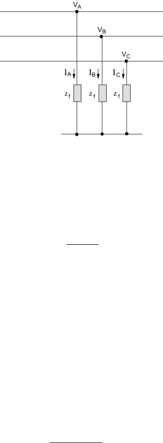
Figure 7.31 A Balanced Three-Phase Fault.
fBB
ZIV
=
(7.44)
fCC
ZIV
=
(7.45)
We can show that
f
ZZ
E
I
+
=
+
+
(7.46)
0
=
−
I
(7.47)
0
0
=
I
(7.48)
The implications of Eqs. (7.47) and (7.48) are obvious. No zero sequence nor
negative sequence components of the current exist. Instead, only positive
sequence quantities are obtained in the case of a balanced three-phase fault.
Example 7.8
For the system of Example 7.5, find the short-circuit currents at the fault point
for a balanced three-phase fault through three impedances each having a value
of Z
f
= j0.05 p.u.
Solution
()
$
9023.3
05.026.0
01
−∠=
+
∠
==
+
j
II
sc
A
7.9 SYSTEM PROTECTION, AN INTRODUCTION
The result of the preceding section provides a basis to determine the
conditions that exist in the system under fault conditions. It is important to take
266
© 2000 CRC Press LLC
the necessary action to prevent the faults, and if they do occur, to minimize
possible damage or possible power disruption. A protection system
continuously monitors the power system to ensure maximum continuity of
electrical supply with minimum damage to life, equipment, and property.
The following are consequences of faults:
1. Abnormally large currents will flow in parts of system with
associated overheating of components.
2. System voltages will be off their normal acceptable levels,
resulting in possible equipment damage.
3. Parts of the system will be caused to operate as unbalanced three-
phase systems, which will mean improper operation of the
equipment.
A number of requirements for protective systems provide the basis for
design criteria.
1. Reliability: Provide both dependability (guaranteed correct
operation in response to faults) and security (avoiding unnecessary
operation). Reliability requires that relay systems perform
correctly under adverse system and environmental conditions.
2. Speed: Relays should respond to abnormal conditions in the least
possible time. This usually means that the operation time should
not exceed three cycles on a 60-Hz base.
3. Selectivity: A relay system should provide maximum possible
service continuity with minimum system disconnection.
4. Simplicity and economy: The requirements of simplicity and
economy are common in any engineering design, and relay
systems are no exception.
A protective system detects fault conditions by continuously
monitoring variables such as current, voltage, power, frequency, and impedance.
Measuring currents and voltages is performed by instrument transformers of the
potential type (P.T.) or current type (C.T.). Instrument transformers feed the
measured variables to the relay system, which in turn, upon detecting a fault,
commands a circuit-interrupting device known as the circuit breaker (C.B.) to
disconnect the faulted section of the system.
An electric power system is divided into protective zones for each
apparatus in the system. The division is such that zones are given adequate
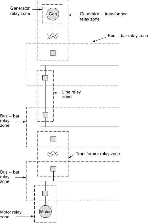
protection while keeping service interruption to a minimum. A single-line
diagram of a part of a power system with its zones of protection is given in
Figure 7.32. It is to be noted that each zone is overlapped to avoid unprotected
(blind) areas.
267
© 2000 CRC Press LLC
7.10 PROTECTIVE RELAYS
A relay is a device that opens and closes electrical contacts to cause the
operation of other devices under electric control. The relay detects intolerable
or undesirable conditions within an assigned area. The relay acts to operate the
appropriate circuit breakers to disconnect the area affected to prevent damage to
personnel and property.
We classify relays according to their function, that is, as measuring or
on-off relays. The latter class is also known as all-or-nothing and includes
relays such as time-lag relays, auxiliary relays, and tripping relays. Here the
relay does not have a specified setting and is energized by a quantity that is
Figure 7.32 Typical Zones of Protection in Part of an Electric Power System.
268
© 2000 CRC Press LLC
either higher than that at which it operates or lower than that at which it resets.
The class of measuring relays includes a number of types with the
common feature that they operate at a predetermined setting. Examples are as
follows:
•
Current relays: Operate at a predetermined threshold value of
current. These include overcurrent and undercurrent relays.
•
Voltage relays: Operate at a predetermined value of voltage.
These include overvoltage and undervoltage relays.
•
Power relays: Operate at a predetermined value of power. These
include overpower and underpower relays.
•
Directional relays:
(i) Alternating current: Operate according to the phase
relationship between alternating quantities.
(ii) Direct current: Operate according to the direction of the
current and are usually of the permanent-magnetic, moving-
coil pattern.
•
Differential relays: Operate according to the scalar or vectorial
difference between two quantities such as current, voltage, etc.
•
Distance relays: Operate according to the “distance” between the
relay’s current transformer and the fault. The “distance” is
measured in terms of resistance, reactance, or impedance.
Relays are made up of one or more fault-detecting units along with the
necessary auxiliary units. Basic units for relay systems can be classified as
being electromechanical units, sequence networks, or solid-state units. The
electromechanical types include those based on magnetic attraction, magnetic
induction, D’Arsonval, and thermal principles. Static networks with three-phase
inputs can provide a single-phase output proportional to positive, negative, or
zero sequence quantities. These are used as fault sensors and are known as
sequence filters. Solid-state relays use low power components, which are
designed into logic units used in many relays.
Electromechanical Relays
We consider some electromechanical type relays such as the plunger
unit, the clapper unit, the polar unit, and the induction disc types.
The plunger type has cylindrical coils with an external magnetic
structure and a center plunger. The plunger moves upward to operate a set of
contacts when the current or voltage applied to the coil exceeds a certain value.
The moving force is proportional to the square of the current in the coil. These
units are instantaneous since no delay is intentionally introduced.
Clapper units have a U-shaped magnetic frame with a movable
armature across the open end. The armature is hinged at one side and spring-
restrained at the other. When the electrical coil is energized, the armature
moves toward the magnetic core, opening or closing a set of contacts with a
269
© 2000 CRC Press LLC
torque proportional to the square of the coil current. Clapper units are less
accurate than plunger units and are primarily applied as auxiliary or “go/no go”
units.
Polar units use direct current applied to a coil wound around the hinged
armature in the center of the magnetic structure. A permanent magnet across the
structure polarizes the armature-gap poles. Two nonmagnetic spacers, located at
the rear of the magnetic frames, are bridged by two adjustable magnetic shunts.
This arrangement enables the magnetic flux paths to be adjusted for pickup and
contact action. With balanced air gaps the armature will float in the center with
the coil deenergized. With the gaps unbalanced, polarization holds the armature
against one pole with the coil deenergized. The coil is arranged so that its
magnetic axis is in line with the armature and at a right angle to the permanent
magnet axis. Current in the coil magnetizes the armature either north or south,
increasing or decreasing any prior polarization of the armature. If the magnetic
shunt adjustment normally makes the armature a north pole, it will move to the
right. Direct current in the operating coil, which tends to make the contact end a
south pole, will overcome this tendency, and the armature will move to the left
to close the contacts.
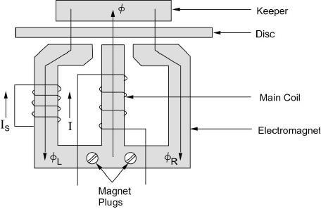
Induction disc units employ the watt hour meter design and use the
same operating principles. They operate by torque resulting from the interaction
of fluxes produced by an electromagnet with those from induced currents in the
plane of a rotatable aluminum disc. The unit shown in Figure 7.33 has three
poles on one side of the disc and a common magnetic keeper on the opposite
side. The main coil is on the center leg. Current (I) in the main coil produces
flux (
φ
), which passes through the air gap and disc to the keeper. The flux
φ
is
divided into
φ
L
through the left-hand leg and
φ
R
through the right-hand leg. A
short-circuited lagging coil on the left leg causes
φ
L
to lag both
φ
R
and
φ
,
producing a split-phase motor action. The flux
φ
L
induces a voltage V
s
, and
current I
s
flows, in phase, in the shorted lag coil. The flux
φ
T
is the total flux
produced by the main coil current (I). The three fluxes cross the disc air gap and
produce eddy currents in the disc. As a result, the eddy currents set up counter
fluxes, and the interaction of the two sets of fluxes produces the torque that
rotates the disc.
A spiral spring on the disc shaft conducts current to the moving contact.
This spring, together with the shape of the disc and the design of electromagnet,
provides a constant minimum operating current over the contact’s travel range.
A permanent magnet with adjustable keeper (shunt) damps the disc, and the
magnetic plugs in the electromagnet control the degree of saturation. The spring
tension, the damping magnet, and the magnetic plugs allow separate and
relatively independent adjustment of the unit’s inverse time overcurrent
characteristics.
Solid-State Units
Solid-state, linear, and digital-integrated circuit logic units are
combined in a variety of ways to provide modules for relays and relay systems.
270
© 2000 CRC Press LLC
Figure 7.33 Induction Disc-Type Relay Unit.
Three major categories of circuits can be identified: (1) fault-sensing and data-
processing logic units, (2) amplification logic units, and (3) auxiliary logic units.
Logic circuits in the fault-sensing and data-processing category employ
comparison units to perform conventional fault-detection duties. Magnitude
comparison logic units are used for overcurrent detection both of instantaneous
and time overcurrent categories. For instantaneous overcurrent protection, a dc
level detector, or a fixed reference magnitude comparator, is used. A variable
reference magnitude comparator circuit is used to ground-distance protection.
Phase-angle comparison logic circuits produce an output when the phase angle
between two quantities is in the critical range. These circuits are useful for
phase, distance, and directional relays.
7.11 TRANSFORMER PROTECTION
A number of fault conditions can arise within a power transformer.
These include:
1. Earth faults: A fault on a transformer winding will result in
currents that depend on the source, neutral grounding impedance,
leakage reactance of the transformer, and the position of the fault
in the windings. The winding connections also influence the
magnitude of fault current. In the case of a Y-connected winding
with neutral point connected to ground through an impedance Z
g
,
the fault current depends on Z
g
and is proportional to the distance
of the fault from the neutral point. If the neutral is solidly
grounded, the fault current is controlled by the leakage reactance,
which depends on fault location. The reactance decreases as the
fault becomes closer to the neutral point. As a result, the fault
current is highest for a fault close to the neutral point. In the case
271
© 2000 CRC Press LLC
of a fault in a
∆
-connected winding, the range of fault current is
less than that for a Y-connected winding, with the actual value
being controlled by the method of grounding used in the system.
Phase fault currents may be low for a
∆
-connected winding due to
the high impedance to fault of the
∆
winding. This factor should
be considered in designing the protection scheme for such a
winding.
2. Core faults due to insulation breakdown can permit sufficient
eddy-current to flow to cause overheating, which may reach a
magnitude sufficient to damage the winding.
3. Interturn faults occur due to winding flashovers caused by line
surges. A short circuit of a few turns of the winding will give rise
to high currents in the short-circuited loops, but the terminal
currents will be low.
4. Phase-to-phase faults are rare in occurrence but will result in
substantial currents of magnitudes similar to earth faults’.
5. Tank faults resulting in loss of oil reduce winding insulation as
well as producing abnormal temperature rises.
In addition to fault conditions within the transformer, abnormal
conditions due to external factors result in stresses on the transformer. These
conditions include: overloading, system faults, overvoltages, and
underfrequency operation.
When a transformer is switched in at any point of the supply voltage
wave, the peak values of the core flux wave will depend on the residual flux as
well as on the time of switching. The peak value of the flux will be higher than
the corresponding steady-state value and will be limited by core saturation. The
magnetizing current necessary to produce the core flux can have a peak of eight
to ten times the normal full-load peak and has no equivalent on the secondary
side. This phenomenon is called magnetizing inrush current and appears as an
internal fault. Maximum inrush occurs if the transformer is switched in when
the supply voltage is zero. Realizing this, is important for the design of
differential relays for transformer protection so that no tripping takes place due
to the magnetizing inrush current. A number of schemes based on the harmonic
properties of the inrush current are used to prevent tripping due to large inrush
currents.
Overheating protection is provided for transformers by placing a
thermal-sensing element in the transformer tank. Overcurrent relays are used as
a backup protection with time delay higher than that for the main protection.
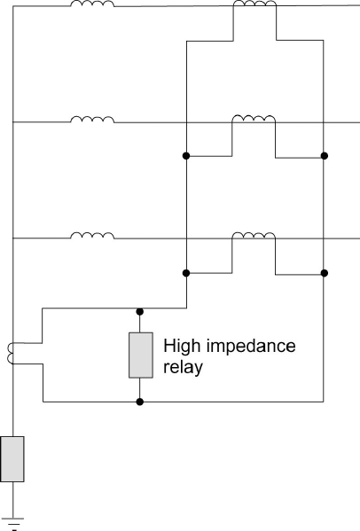
Restricted earth fault protection is utilized for Y-connected windings. This
scheme is shown in Figure 7.34. The sum of the phase currents is balanced
against the neutral current, and hence the relay will not respond to faults outside
the winding.
272
© 2000 CRC Press LLC
Figure 7.34 Restricted Ground Fault Protection for a Y Winding.
Differential protection is the main scheme used for transformers. The
principle of a differential protection system is simple. Here the currents on each
side of the protected apparatus for each phase are compared in a differential
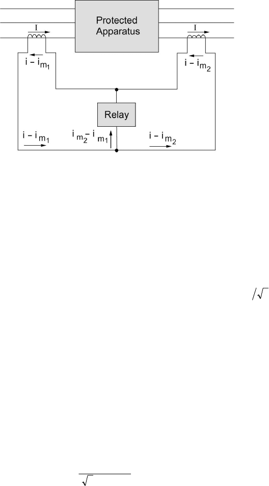
circuit. Any difference current will operate a relay. Figure 7.35 shows the relay
circuit for one phase only. On normal operation, only the difference between
the current transformer magnetizing currents
1
m
i
and
2
m
i
passes through the
relay. This is due to the fact that with no faults within the protected apparatus,
the currents entering and leaving are equal to i. If a fault occurs between the
two sets of current transformers, one or more of the currents (in a three-phase
system) on the left-hand side will suddenly increase, while that on the right-hand
side may decrease or increase with a direction reversal. In both instances, the
total fault current will flow through the relay, causing it to operate. In units
where the neutral ends are inaccessible, differential relays are not used, but
reverse power relays are employed instead.
A number of considerations should be dealt with in applying
differential protection, including:
273
© 2000 CRC Press LLC
Figure 7.35 Basic Differential Connection.
1. Transformer ratio: The current transformers should have ratings to
match the rated currents of the transformer winding to which they
are applied.
2. Due to the 30
°
-phase change between Y- and
∆
-connected
windings and the fact that zero sequence quantities on the Y side
do not appear on the terminals of the
∆
side, the current
transformers should be connected in Y for a
∆
winding and in
∆
for
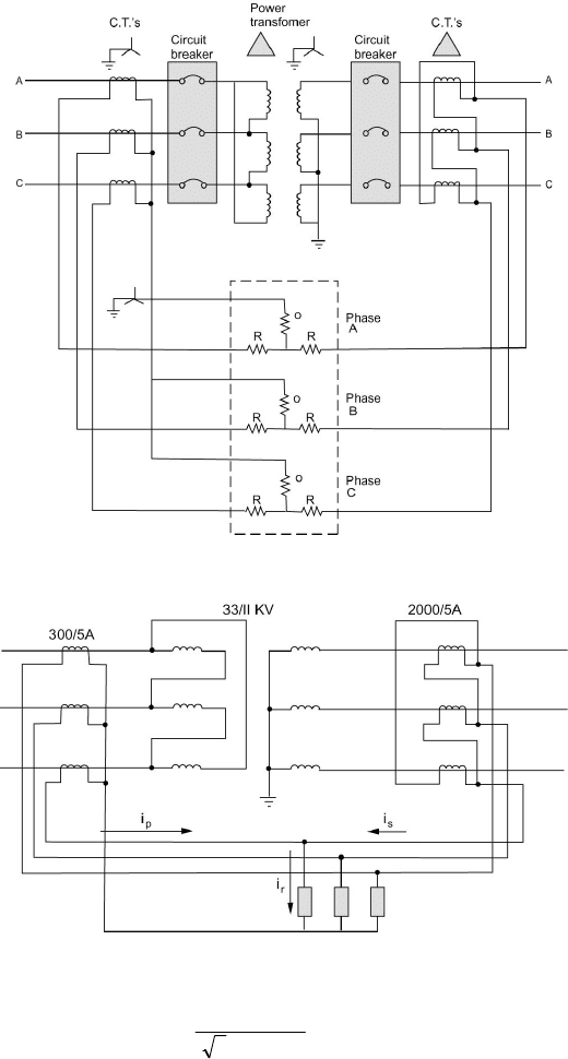
a Y winding. Figure 7.36 shows the differential protection scheme
applied to a
∆
/Y transformer. When current transformers are
connected in
∆
, their secondary ratings must be reduced to
(
)
31
times the secondary rating of Y-connected transformers.
3. Allowance should be made for tap changing by providing
restraining coils (bias). The bias should exceed the effect of the
maximum ratio deviation.
Example 7.9
Consider a
∆
/Y-connected, 20-MVA, 33/11-kV transformer with differential
protection applied, for the current transformer ratios shown in Figure 7.37.
Calculate the relay currents on full load. Find the minimum relay current setting
to allow 125 percent overload.
Solution
The primary line current is given by
()
()
A 91.349
10333
1020
3
6
=
×
×
=
p
I
The secondary line current is
274
© 2000 CRC Press LLC
Figure 7.36 Differential Protection of a ∆/Y Transformer.
Figure 7.37 Transformer for Example 7.9.
()
()
A73.1049
10113
1020
3
6
=
×
×
=
s
I
The C.T. current on the primary side is thus
