El-Hawary M.E. Electrical Energy Systems
Подождите немного. Документ загружается.

275
© 2000 CRC Press LLC
A832.5
300
5
91.349
=
=
p
i
The C.T. current in the secondary side is
A545.43
2000
5
73.1049
=
=
s
i
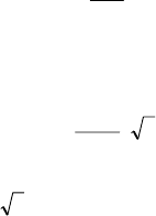
Note that we multiply by
3
to obtain the values on the line side of the
∆
-
connected C.T.’s. The relay current on normal load is therefore
A287.1545.4832.5
=−=−=
spr
iii
With 1.25 overload ratio, the relay setting should be
A61.1)287.1)(25.1(
==
r
I
Buchholz Protection
In addition to the above-mentioned protection schemes, it is common
practice in transformer protection to employ gas-actuated relays for alarm and
tripping. One such a relay is the Buchholz relay.
Faults within a transformer will result in heating and decomposing of
the oil in the transformer tank. The decomposition produces gases such as
hydrogen, carbon monoxide, and light hydrocarbons, which are released slowly
for minor faults and rapidly for severe arcing faults. The relay is connected into
the pipe leading to the conservator tank. As the gas accumulates, the oil level
falls and a float F is lowered and operates a mercury switch to sound an alarm.
Sampling the gas and performing a chemical analysis provide a means for
classifying the type of fault. In the case of a winding fault, the arc generates gas
at a high release rate that moves the vane V to cause tripping through contacts
attached to the vane.
Buchholz protection provides an alarm for a number of fault conditions
including:
1. Interturn faults or winding faults involving only lower power
levels.
2. Core hot spots due to short circuits on the lamination insulation.
3. Faulty joints.
4. Core bolt insulation failure.
276
© 2000 CRC Press LLC
7.12 TRANSMISSION LINE PROTECTION
The excessive currents accompanying a fault, are the basis of
overcurrent protection schemes. For transmission line protection in
interconnected systems, it is necessary to provide the desired selectivity such
that relay operation results in the least service interruption while isolating the
fault. This is referred to as relay coordination. Many methods exist to achieve
the desired selectivity. Time/current gradings are involved in three basic
methods discussed below for radial or loop circuits where there are several line
sections in series.
Three Methods of Relay Grading
A) Time Grading
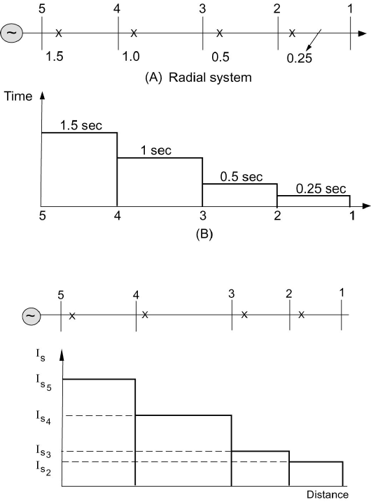
Time grading ensures that the breaker nearest to the fault opens first, by
choosing an appropriate time setting for each of the relays. The time settings
increase as the relay gets closer to the source. A simple radial system shown in
Figure 7.38 demonstrates this principle.
A protection unit comprising a definite time-delay overcurrent relay is
placed at each of the points 2, 3, 4, and 5. The time-delay of the relay provides
the means for selectivity. The relay at circuit breaker 2 is set at the shortest
possible time necessary for the breaker to operate (typically 0.25 second). The
relay setting at 3 is chosen here as 0.5 second, that of the relay at 4 at 1 second,
and so on. In the event of a fault at F, the relay at 2 will operate and the fault
will be isolated before the relays at 3, 4, and 5 have sufficient time to operate.
The shortcoming of the method is that the longest fault-clearing time is
associated with the sections closest to the source where the faults are most
severe.
B) Current Grading
Fault currents are higher the closer the fault is to the source and this is
utilized in the current-grading method. Relays are set to operate at a suitably
graded current setting that decreases as the distance from the source is increased.
Figure 7.39 shows an example of a radial system with current grading. The
advantages and disadvantages of current grading are best illustrated by way of
examples.
C) Inverse-Time Overcurrent Relaying
The inverse-time overcurrent relay method evolved because of the
limitations imposed by the use of either current or time alone. With this method,
the time of operation is inversely proportional to the fault current level, and the
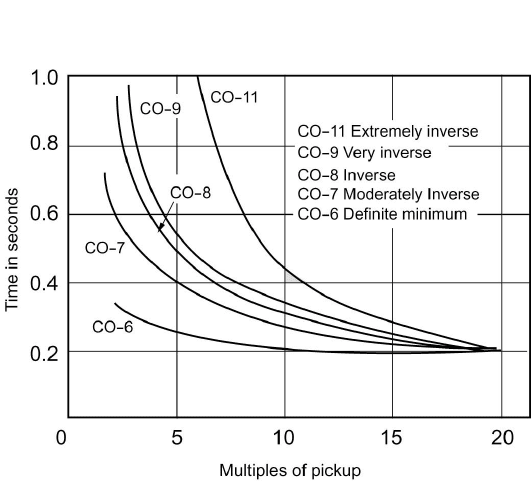
actual characteristics are a function of both time and current settings. Figure
7.40 shows some typical
inverse-time relay characteristics. Relay type CO-7 is
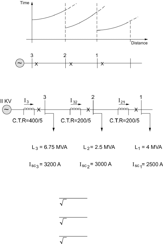
in common use. Figure 7.41 shows a radial system with time-graded inverse
277
© 2000 CRC Press LLC
Figure 7.38 Principles of Time Grading.
Figure 7.39 Current Grading for a Radial System.
relays applied at breakers 1, 2, and 3.
For faults close to the relaying points, the inverse-time overcurrent
method can achieve appreciable reductions in fault-clearing times.
The operating time of the time-overcurrent relay varies with the current
magnitude. There are two settings for this type of relay:
1. Pickup current is determined by adjusted current coil taps or
current tap settings (C.T.S.). The pickup current is the current that
causes the relay to operate and close the contacts.
2. Time dial refers to the reset position of the moving contact, and it
278
© 2000 CRC Press LLC
varies the time of operation at a given tap setting and current
magnitude.
The time characteristics are plotted in terms of time versus multiples of
current tap (pickup) settings, for a given time dial position. There are five
different curve shapes referred to by the manufacturer:
CO-11 Extreme inverse
CO-9 Very inverse
CO-8 Inverse
CO-7 Moderately inverse
CO-6 Definite minimum
These shapes are given in Figure 7.40.
Figure 7.40 Comparison of CO Curve Shapes.
Example 7.10
Consider the 11-kV radial system shown in Figure 7.42. Assume that all loads
have the same power factor. Determine relay settings to protect the system
assuming relay type CO-7 (with characteristics shown in Figure 7.43) is used.
Solution
The load currents are calculated as follows:
279
© 2000 CRC Press LLC
Figure 7.41 Time-Graded Inverse Relaying Applied to a Radial System.
Figure 7.42 An Example Radial System.
()
()
()
A28.354
10113
1075.6
A22.131
10113
105.2
A95.209
10113
104
3
6
3
3
6
2
3
6
1
=
×
×
=
=
×
×
=
=
×
×
=
I
I
I
The normal currents through the sections are calculated as
A44.695
A16.341
A95.209
332
22132
121
=+=
=+=
==
III
III
II
S
With the current transformer ratios given, the normal relay currents are
280
© 2000 CRC Press LLC
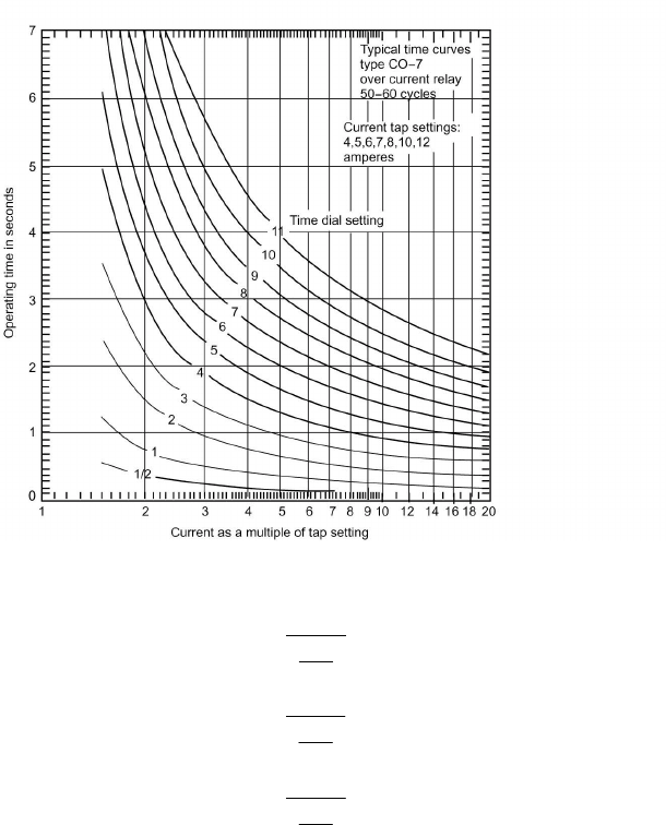
Figure 7.43 CO-7 Time-Delay Overcurrent Relay Characteristics.
A69.8
5
400
44.695
A53.8
5
200
16.341
A25.5
5
200
92.209
32
21
==
==
==
S
i
i
i
We can now obtain the current tap settings (C.T.S.) or pickup current in
such a manner that the relay does not trip under normal currents. For this type
of relay, the current tap settings available are 4, 5, 6, 7, 8, 10, and 12 amperes.
For position 1, the normal current in the relay is 5.25 A; we thus choose
(C.T.S.)
1
= 6 A
For position 2, the normal relay current is 8.53 A, and we choose
(C.T.S.)
2
= 10 A

281
© 2000 CRC Press LLC
Similarly for position 3,
(C.T.S.)
3
= 10 A
Observe that we have chosen the nearest setting higher than the normal current.
The next task is to select the intentional delay indicated by the time dial
setting (T.D.S.). We utilize the short-circuit currents calculated to coordinate
the relays. The current in the relay at 1 on a short circuit at 1 is
A5.62
5
200
2500
1
=
=
SC
i
Expressed as a multiple of the pickup or C.T.S. value, we have
42.10
6
5.62
(C.T.S.)
1
1
==
SC
i
We choose the lowest T.D.S. for this relay for fastest action. Thus
2
1
(T.D.S.)
1
=
By reference to the relay characteristic, we get the operating time for relay 1 for
a fault at 1 as
s15.0
1
1
=
T
To set the relay at 2 responding to a fault at 1, we allow 0.1 second for
breaker operation and an error margin of 0.3 second in addition to
1
1
T
. Thus,
s55.03.01.0
22
12
=++=
TT
The short circuit for a fault at 1 as a multiple of the C.T.S. at 2 is
25.6
10
5.62
(C.T.S.)
2
1
==
SC
i
From the characteristics for 0.55-second operating time and 6.25 ratio, we get
2(T.D.S.)
2
≅
The final steps involve setting the relay at 3. For a fault at bus 2, the

282
© 2000 CRC Press LLC
short-circuit current is 3000 A, for which relay 2 responds in a time T
22
obtained
as follows:
5.7
10
5
200
3000
(C.T.S.)
2
2
=
=
SC
i
For the (T.D.S.)
2
= 2, we get from the relay’s characteristic,
T
22
= 0.50 s
Thus allowing the same margin for relay 3 to respond to a fault at 2, as for relay
2 responding to a fault at 1, we have
s90.0
3.01.0
2232
=
++=
TT
The current in the relay expressed as a multiple of pickup is
75.3
10
5
400
3000
(C.T.S.)
3
2
=
=
SC
i
Thus for T
3
= 0.90, and the above ratio, we get from the relay’s characteristic,
5.2(T.D.S.)
3
≅
We note here that our calculations did not account for load starting currents that
can be as high as five to seven times rated values. In practice, this should be
accounted for.
Pilot-Wire Feeder Protection
Graded overcurrent feeder protection has two disadvantages. First, the
grading settings may lead to tripping times that are too long to prevent damage
and service interruption. Second, satisfactory grading for complex networks is
quite difficult to attain. This led to the concept of “unit protection” involving
the measurement of fault currents at each end of a limited zone of the feeder and
the transmission of information between the equipment at zone boundaries. The
principle utilized here is the differential (often referred to as Merz-price)
protection scheme. For short feeders, pilot-wire schemes are used to transmit
the information. Pilot-wire differential systems of feeder protection are
classified into three types: (1) the circulating-current systems, (2) the balanced-
voltage systems, and (3) the phase-comparison (Casson-Last) system. All three
systems depend on the fact that, capacitance current neglected, the instantaneous
value of the current flowing into a healthy conductor at one end of the circuit is
283
© 2000 CRC Press LLC
equal to the instantaneous current flowing out of the conductor at the other end,
so that the net instantaneous current flowing into or out of the conductor is zero
if the conductor is healthy. If, on the other hand, the conductor is short-circuited
to earth or to another conductor at some point, then the net current flowing into
or out of the conductor is equal to the instantaneous value of the current flowing
out of or into the conductor at the point of fault.
7.13 IMPEDANCE-BASED PROTECTION PRINCIPLES
This section discusses the principles involved in protecting components
such as transmission lines on the basis of measuring the input impedance of the
component. We first discuss the idea of an X-R diagram which is an excellent
graphical tool to demonstrate principles of impedance protection systems. The
concept of relay compartors is then introduced. The specific parameter choices
ot allow for the creation of impedance relays based on either amplitude or phase
comparisons are then discussed. The section concludes with a discussion of
distance protection.
A) The X-R Diagram
Consider a transmission line with series impedance Z
L
and negligible
shunt admittance. At the receiving end, a load of impedance Z
R
is assumed. The
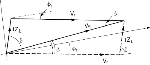
phasor diagram shown in Figure 7.44 is constructed with I taken as the
reference. The phasor diagram represents the relation
rLS
VIZV
+=
(7.49)
giving rise to the heavy-lines diagram rather than the usual one shown by the
dashed line. On the diagram,
δ
is the torque angle, which is the angle between
V
s
and V
r
.
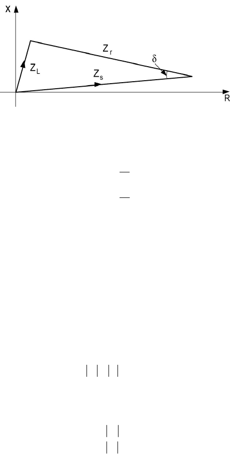
If the phasor diagram, Eq. (7.49), is divided by the current I, we obtain
the impedance equation
rLs
ZZZ
+=
(7.50)
Figure 7.44 Voltage Phasor Diagram.
284
© 2000 CRC Press LLC
Figure 7.45 Impedance Diagram.
where
I
V
Z
I
V
Z
r
r
s
s
=
=
An impedance diagram is shown in Figure 7.45. ThisiscalledtheX-R diagram
since the real axis represents a resistive component (R), and the imaginary axis
corresponds to a reactive component (X). The angle
δ
appears on the impedance
diagram as that between Z
s
and Z
r
. The evaluation of Z
r
from complex power S
R
and voltage V
r
is straightforward.
B) Relay Comparators
Relay comparators can have any number of input signals. However, we
focus our attention here on the two-input comparator shown schematically in
Figure 7.46. The input to the two transformer circuits 1 and 2 includes the line
voltage V
L
and current I
L
. The output of transformer 1 is V
1
, and that of
transformer 2 is V
2
. Both V
1
and V
2
are input to the comparator, which produces
a trip (operate) signal whenever
12
VV
>
in an amplitude comparison mode.
We will start the analysis by assuming that the line voltage V
L
is the
reference phasor and that the line current lags V
L
by and angle
φ
L
. Thus,
LLL
LL
II
VV
φ
−∠=
∠=
0
The impedance Z
L
is thus
