Dubois E., Gray P., Nigay L. (Eds.) The Engineering of Mixed Reality Systems
Подождите немного. Документ загружается.


256 P. Keitler et al.
13.2.2 Data Flow Networks
SRGs are a descriptive rather than an operational specification of a certain setup and
are not directly usable by an application. Rather, for efficient use by the Ubitrack
runtime system that is included into the applications, they have to be converted into
data flow networks (DFNs). DFNs consist of computational units that operate on
tracking data.
DFNs are instances of data flow graphs (DFGs). DFGs are directed graphs and
their nodes represent the components to be instantiated in the DFN. Edges represent
the flow of tracking data between these components. Sources in a DFG gener-
ally represent sources of tracking data (i.e., tracking devices). Sinks correspond to
interfaces to applications or to other data flow graphs.
Fig. 13.2 Data flow network corresponding to the SRG shown in Fig. 13.1b. An inversion, fol-
lowed by a multiplication, is needed to compute the dashed edge of Fig. 13.1a from the two solid
edges
Figure 13.2 shows the data flow graph that computes the spatial relationship
between the HMD and the target in the SRG of Fig. 13.1 The tracking data of the
HMD are inverted and then concatenated with the tracking data of the target.
The Ubitrack runtime environment uses such data flow networks. At this
level, Ubitrack is comparable to the approaches taken in other systems, such as
OpenTracker [20]. In fact, we are able to export data flow networks that have been
generated from SRGs into applications that use OpenTracker, using the Ubiquitous
Tracking Query Language (UTQL) data exchange format [18, 14] (in support
of R1).
13.2.3 Spatial Relationship Patterns
This section describes how SRGs can be transformed into DFGs. To this end, Pustka
introduced the concept of spatial relationship patterns [17]. A pattern corresponds
to a computational unit, i.e., a node, in a DFG. Tracking data are provided to the
computational unit via inputs. It is transformed and then sent out via the output.
Good examples are the inversion and multiplication nodes in the DFG of Fig. 13.2
13.2.3.1 Basic Concept
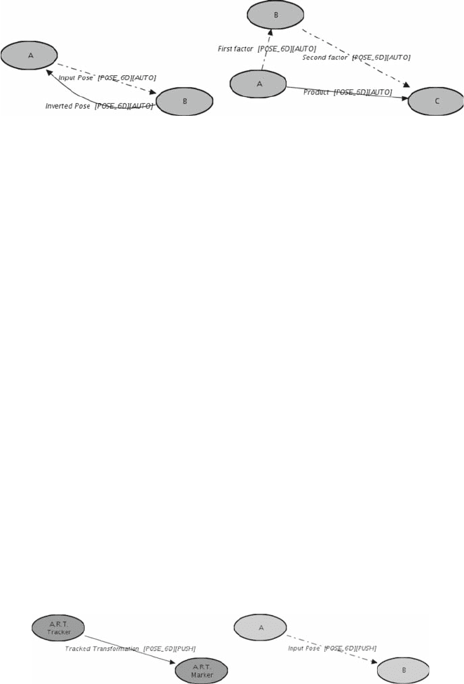
Spatial relationship patterns are depicted as template SRGs. They describe the effect
of a computational unit on an SRG. For example, the inversion pattern in Fig. 13.3a

13 Tracking for Mixed and Augmented Reality Systems 257
(a) Inversion (fullpattern) (b) Multiplication (fullpattern)
Fig. 13.3 Basic spatial relationship patterns for the inversion and multiplication of tracking data
states that, for a given SRG edge from node A to B, inversion adds a new edge
to the SRG going in the reverse direction. Similarly, the multiplication pattern in
Fig. 13.3b states that an SRG edge from A to B and an edge from B to C can be
concatenated by multiplying the transformations. As a result, a new edge from A
to C can be added to the SRG. Component inputs in the DFG correspond to input
edges of the pattern. They are shown as dashed lines, and the associated input nodes
as light gray ellipses. The resulting component output in the DFG corresponds to
an output edge of the pattern. It is shown by a solid line and the associated output
nodes by darker ellipses. If the input edges and nodes of a pattern match a part of an
SRG, the output edges and nodes can be added to the graph. At the same time, the
corresponding computational unit can be added to the DFG.
In addition to full patterns that have both input edges and output edges, there
are base patterns that have only output nodes and edges, such as the tracker
pattern in Fig. 13.4a Since it has an empty input section, it can be applied
any time. It is used to add tracking devices as source computational units to
the DFG.
Similarly, query patterns have only input nodes and edges (Fig. 13.4b). They
connect the tracking setup to an application, in the form of a query for information
about a specific spatial relationship in a scene. An example is the pose of the target
relative to the HMD in Fig. 13.1a Generally, all base/query patterns have the same
structure, an output/input edge with output/input source and sink nodes.
(a) A.R.T. Tracker (basepattern) (b) Application Push Sink (querypattern)
Fig. 13.4 Spatial relationship patterns for a tracking device and to connect the Ubitrack runtime
system to an application
258 P. Keitler et al.
13.2.3.2 Synchronization Issues
To properly handle measurements that are generated asynchronously by independent
sensors, each edge in an SRG is attributed with its synchronization mode, push or
pull. Pushed measurements travel downward from source toward sink through a
DFN, e.g., when a tracker such as a camera sends new data into the network at its
own speed. Pulled measurements are pulled upward in a DFN. A pull operation may
be initiated for example by an application requesting measurements with a specific
time stamp via the Application Pull Sink component. Push as well as pull events are
propagated recursively through the data flow network.
Synchronization problems occur when two or more unsynchronized inputs have
to be combined by a computational unit, such as the multiplication component. The
measurements then need to be valid for the same point in time. When a pull request
occurs on the output, measurements have to be pulled for this time stamp on all
inputs. When a push event occurs for one input edge, measurements for the same
time stamp have to be pulled on the other inputs. The result can then be computed
and pushed onward on the output. Generally, it is not possible to have more than one
input in push mode, except when both measurements come from the same tracker or
are otherwise synchronized in hardware. Therefore, all except one of them should
be in pull mode. To this end, suitable conversion facilities must be included. The
Buffer (constant interpolation), Linear Interpolation, and Kalman Filter components
convert measurements from push to pull whereas the Sampler component converts
from pull to push. Refer to [16] for more details.
13.2.3.3 Pattern Categories
A large number of patterns and associated computational units have already been
integrated into Ubitrack [17]. For documentation purposes and for interactive use in
trackman, they are categorized with respect to their structure (i.e., as base, full, and
query patterns) and also with respect to their semantics:
• Sensor patterns describe how tracking data are provided to the data flow net-
work. This mainly comprises driver components retrieving data from hardware.
• Basic patterns describe trivial transformation steps such as inversion or interpo-
lation of a transformation or concatenation of two transformations.
• Calibration patterns represent algorithms such as the hand–eye calibration
or absolute-orientation algorithm which are used to determine static spatial
relationships under certain boundary conditions.
• Fusion patterns represent algorithms which can be used to somehow fuse
tracking data to obtain a better, more accurate, or a more general result.
• Persistence patterns represent components that write tracking or calibration data
to a file or read it from there.
• Network patterns represent components that send/receive tracking data to/from
the network. They are needed to link independent DFNs.

13 Tracking for Mixed and Augmented Reality Systems 259
• Application patterns represent components that transfer or receive tracking data
to/from an application. This principally enables applications not only to consume
tracking data but also to transform it somehow and reinject it into the data flow
network. Other patterns in this category include render components, which create
OpenGL-based 3D graphics output based on tracking data.
Table 13.1 presents a representative subset of patterns,
2
classified according to
their structure and semantics. For the application and persistence patterns, there
exist pairs of corresponding base and query patterns, such as Player and Recorder
for logging and replaying tracking data or Calibration Reader and Calibration Writer
maintaining the calibration or registration data of a static transformation in files.
The application source and sink patterns represent endpoints in the DFN which
interface it to the application. The Application Pull Source is one of few data flow
sources having type pull. It retrieves current tracking data at any time via a callback
interface from the application. Similarly, the Application Push Sink pushes data into
the application via a callback interface. In both cases, the DFN initiates the flow of
tracking data. Application Push Source and Pull Sink, on the contrary, work without
a callback mechanism and the application initiates the flow of tracking data. Some
calibration patterns will be introduced in Section 13.5.1. For more details, refer to
[17].
Table 13.1 Pattern categorization matrix showing a subset of the existing Ubitrack patterns. The
transformation types are neglected for t he sake of readability
Syntax
Base pattern Full pattern Query pattern
Semantics Sensor A.R.T. tracker
static transformation
Basic Multiplication
Inversion
Buffer
Interpolation
Collector
Gate
Sampler
Calibration Hand–eye calibration
Absolute orientation
Tip calibration
Fusion Kalman Filter
Functional fusion
Persistence Player Recorder
calibration reader calibration Writer
Network Network source Network Sink
Application Application Push Source Application Push Sink
Application Pull Source Application Pull Sink
X3D object
Background image
2
A comprehensive reference is provided at http://campar.in.tum.de/UbiTrack/WebHome

260 P. Keitler et al.
13.2.4 SRG Design Activities
Pattern modeling consists of three major activities:
• A1: Description of the tracking environment All mobile and stationary sen-
sors and all real and virtual objects are identified. Their known or tracked spatial
relationships to one another are described. This activity mainly uses base patterns.
• A2: Deduction of indirect spatial relationships Full patterns are applied to
suitable parts of an SRG either by an automatic pattern matching process or
interactively by the AR-engineer.
• A3: Definition of the runtime interface to the application On the basis of query
patterns, application interface(s) are inserted i nto the SRG.
trackman can assist AR-engineers in generating SRGs for a given tracking environ-
ment (A1 and A3). Ubitrack can use pattern matching techniques to automatically
derive a DFG from a given SRG [11, 19] (A2). AR-engineers can influence the cre-
ation of DFGs manually in trackman, supporting requirements R2 and R4 (A2). The
interactive variants of t hese activities are described in the subsequent sections.
13.3 trackman: Interactive Modeling of Spatial Relationships
trackman is a configuration and monitoring tool for tracking setups. It has a graphi-
cal interface, showing the current configuration of a setup in terms of both SRG and
DFG. It also provides interactive means to access all patterns that are known to the
Ubitrack runtime s ystem and to integrate them into the current configuration.
13.3.1 System Architecture
In order to keep trackman independent from Ubitrack development and to ensure its
compatibility with upcoming patterns, it was designed as a lightweight and generic
tool. Architecturally, it is organized as a Ubitrack application.
trackman does not have special knowledge of patterns but rather imports the
current set of available patterns from external description files that come with
the Ubitrack runtime library. The description language is based on the UTQL
3
data exchange format [18]. In addition to the mere graph structure of the pat-
terns, it also allows to specify important meta information. Type information for
node/edge/pattern attributes (see Section 13.2.1.2 for the most important ones)
as well as pattern documentation has to be provided. The resulting pattern tem-
plate specification language XML schema
4
allows for the formal description of
3
http://ar.in.tum.de/static/files/ubitrack/utql/utql.xsd
4
http://ar.in.tum.de/static/files/ubitrack/utql/utql_templates.xsd, http://ar.in.tum.de/static/files/
ubitrack/utql/utql_types.xsd

13 Tracking for Mixed and Augmented Reality Systems 261
Fig. 13.5 The trackman graphical modeling tool for spatial relationship graphs
available patterns. trackman uses the meta information to allow for convenient con-
figuration of node, edge, and pattern attributes in its property editor and to display
documentation to the user, as can be seen in Fig. 13.5.
13.3.2 Graphical Layout
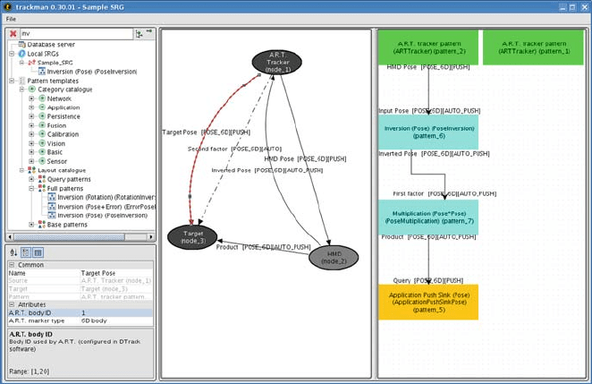
Figure 13.5 presents a screen dump of trackman showing the interactive construction
of the SRG and DFG of Figs. 13.1 and 13.2. The tree on the left shows excerpts
of the list of all patterns, accessible with respect to both semantic and structural
(layout) categories. Below, the property editor allows to inspect and edit settings
associated with the selected node, edge, or pattern. On the top left, a search facility
allows the AR-engineer to restrict the displayed elements in the tree to only those
patterns t hat contain all specified strings.
The central area is tiled, showing the current SRG and/or the DFG. In the DFG
pane on the right, data sources (corresponding to base patterns, green) are the
uppermost components, followed by intermediate computational units (full patterns,
cyan), and finally the lowermost data sinks (query patterns, orange). The latter ones
represent interfaces to applications. AR-engineers can alter the tracking setup in the
SRG window. Resulting updates are automatically brought to the DFG window. At
intermediate stages of the configuration process, not all nodes in the DFG window
need to be integrated into the data flow network. For example, the right green node
in Fig. 13.5 has not yet been connected to other modules.

262 P. Keitler et al.
13.3.3 Interactive SRG Generation
Starting with an empty work area in t rackman, we use base and query patterns
similar to those shown in Fig. 13.4 to describe the directly existing spatial rela-
tionships in the tracking environment and the application requests. To this end, they
are dragged from the tree view on the left to the SRG editing workspace.
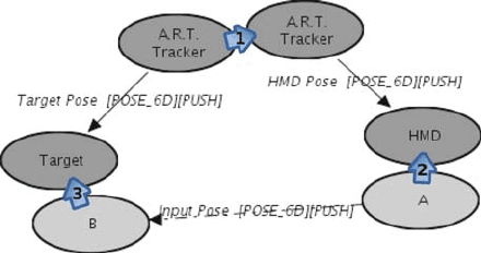
For the SRG in Fig. 13.1a, the A.R.T. Tracker pattern is dragged twice into the
work area – once for each of the two targets. Names, IDs, and other attributes are
modified by selecting the respective node, edge, or pattern and applying the set-
tings in the property editor. The query pattern Application Sink is dragged into the
workspace to describe the request that an edge be provided which describes the
spatial r elationship between the HMD and the target (see Fig. 13.6).
Fig. 13.6 Identification of coordinate systems via node unification. The indicated unification steps
result in the SRG shown in Fig. 13.1a.
Using the node unification interaction scheme, all three patterns can be merged to
form a single graph. To express that two nodes from different patterns are identical
in the SRG, AR-engineers can drag one node on top of the other one. As a result
of this operation, the subgraphs are merged at this node. Node unification can be
applied to all combinations of input and/or output nodes. Nodes that result from
unification of at least two output nodes are shown darker than normal output nodes
and with a white label. Nodes within a single pattern cannot be unified (principle of
pattern atomicity). Figure 13.6 shows the node unification steps which lead to the
SRG shown in Fig. 13.1a.
13.3.4 Interactive Deduction of Spatial Relationships
Another interaction scheme i s needed to let AR-engineers specify which operations
should be applied to the tracking data such that additional spatial relationships can
be derived. To this end, full patterns have to be integrated into the SRG, thereby
adding further (deduced) edges in terms of their output edges.

13 Tracking for Mixed and Augmented Reality Systems 263
Fig. 13.7 Identification of data input and output of patterns via edge matching. The indicated
matching steps result in the SRG shown in Fig. 13.1b
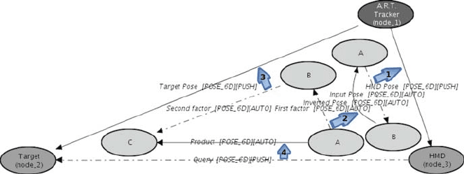
By edge matching, an edge from the input section of a new pattern is matched
against an edge that exists already in the SRG or that is part of the output sec-
tion of another pattern. The operation also immediately updates the corresponding
DFG, linking the input of the computational unit with the output of another
component.
The edge matching operation is performed by selecting the two edges, and
then invoking the match operation from the menu. Both edges must have the
same edge characteristics (according to Section 13.2.1) and illegal matchings are
inhibited.
Edge-matching implies node unification on the source and sink nodes, respec-
tively, if necessary. Edges belonging to the same pattern cannot be matched (again
due to pattern atomicity). The edge-matching steps which lead to the SRG shown in
Fig. 13.1b are depicted in Fig. 13.7.
trackman supports the analysis of synchronization issues. For many full patterns,
it can perform the recursive propagation of synchronization mode flags on-the-fly
(according to Section 13.2.3. For other full and query patterns that only allow for a
specific constellation of mode flags, still a consistency check can be performed.
Edge matchings with incompatible sync flags are inhibited. The conflict can be
resolved manually by converting some push edges to pull mode.
13.3.5 More Modeling Functionality
With node unification and edge matching, SRGs can be constructed from scratch.
Additional functionality is needed when dealing with existing SRGs. This is
important for the maintenance of existing setups (R4) and also to recover from
modeling mistakes. Therefore, trackman also provides the following interaction
schemes.

264 P. Keitler et al.
(a) Isolate pattern outputs (b) Isolate pattern inputs
Fig. 13.8 Result of the isolate pattern output and input operations, invoked on the Multiplication
pattern contained in Fig. 13.1b
• Isolate Pattern Outputs: t rackman is able to separate the output edges of the pat-
tern from connected nodes/edges in the input section of other patterns. The effect
of this operation is shown in Fig. 13.8a. The output edge of the Multiplication
pattern contained in the sample SRG (Fig. 13.1b) is isolated from matched input
edges. Concretely, the matching step 4 of Fig. 13.7 is revoked.
• Isolate Pattern Inputs: To complement the previous scheme, trackman is
also able to separate the input edges of a pattern from its context, effectively
annulling all dependencies between these input edges and corresponding output
nodes/edges of other patterns. Invoking this operation on the same Multiplication
pattern results in Fig. 13.8b. The edge-matching steps 2 and 3 as depicted in Fig.
13.7 are revoked. This implies also the separation of those input nodes that are
neither source nor sink of an output edge of the pattern, such as node “B” of the
Multiplication pattern.
• Isolate Entire Pattern: This operation combines the two operations above and
brings the pattern back to its atomic form.
• Delete Pattern: The pattern is removed from the current SRG. It does not matter
whether the pattern was integrated in some larger SRG structure or existed in its
atomic form. In the former case, an isolate pattern step is implicitly performed
first.
• Hide Pattern: Parts of the SRG are hidden to provide an abstracted, clearer view
of the SRG in the editor window. trackman provides this functionality on a per-
pattern basis. This helps to maintain clarity in large SRGs such as the one shown
in Fig. 13.12 which consists of approximately 100 patterns.
13.3.6 Ordering of Design Activities
It is up to the AR-engineer to decide about a suitable design approach. Patterns may
be added to the SRG in any sequence. Furthermore, patterns may be combined using
the node unification and edge-matching metaphors in any sequence. The output edge
of a selected pattern may therefore be associated with a subsequent input edge even
though it is currently unclear how the output edge can be deduced since the input

13 Tracking for Mixed and Augmented Reality Systems 265
edges of that pattern have not been matched yet. A valid DFG, of course, requires
all i nput edges to have been matched properly.
The design process may therefore be started either with the environment, some
basic fusion algorithm, or also the application interface. The first case might also be
denoted as a bottom-up approach since the AR-engineer starts with physical enti-
ties (A1) and refines information step by step (A2), resulting in an application-level
(A3) piece of information. In the opposite top-down approach the engineer could
start with the application interface (A3) and drill down through various algorithms
(A2) to finally reach real-world sensors and objects (A1). For clarification, going
up according to the degree of abstraction from raw sensor measurements toward
application-level data comes along with going down in the data flow from data
sources to data sinks.
13.4 Advanced Interactive Modeling Concepts
This section describes two techniques which can further ease the SRG modeling pro-
cess. Semi-automatic modeling automates simple operations and lets the user focus
on the essential deduction steps. Meta patterns provide best-practice solutions to
well-known problems, reducing the modeling problem to the addition of a few pat-
terns only. Both techniques significantly reduce the amount of modeling operations
that have to be performed manually.
13.4.1 Semi-automatic Modeling
Manual pattern matching can become a very tedious procedure. In more complex
setups, the amount of patterns to be integrated in the SRG increases quickly. A con-
catenation of n edges requires [n−1] applications of the Multiplication pattern. In
addition to that, some edges have to be inverted. In practice, approximately half
of all matchings of full patterns fall upon the Inversion and Multiplication patterns
(e.g., 22 out of 42 in Fig. 13.12). Automatic pattern matching can relieve the user
from the trivial aspects of these and other modeling operations. Figure 13.9 depicts
(a) Deduction problem (b) Possible Solution
Fig. 13.9 Typical modeling situation which requires many applications of full patterns
