Dake L.P. Fundamentals of reservoir engineering
Подождите немного. Документ загружается.

IMMISCIBLE DISPLACEMENT 341
owc
pp P gH
ρ
−==∆ (10.2)
where ∆
ρ
=
ρ
w
-
ρ
o
. Furthermore, considering in detail the geometry at the interface in
the capillary tube, fig. 10.4. If the curvature is approximately spherical with radius R,
then in applying the Laplace equation, (10.1), r
1
= r
2
= R at all points on the interface.
Also if r is the radius of the capillary tube, then r = RcosΘ and therefore
owc
2cos
pp P gh
r
σ
ρ
Θ
−== =∆
(10.3)
This equation is frequently used to draw a comparison between simple capillary rise
experiments, as described above, and capillary rise in the reservoir, the porous tracts
in the latter being likened to a collection of capillary tubes with different radii. In this
comparison it can be seen that the capillary rise of water will be greater for small r,
equ. (10.3), and will decrease as r increases. The decrease in capillary rise will be
apparently a continuous function due to the continuous range of pore capillaries in the
reservoir and will define, in fact, the capillary pressure-saturation relation. This
argument is frequently applied to consider the static case of water distribution above
the 100% water saturation level in the reservoir, under initial conditions, for which the
drainage capillary pressure curve is required. There will generally be no sharp interface
between the water and oil but, rather, a zone in which saturations decrease with height
above the 100% water saturation level, at which P
c
= 0, in accordance with the capillary
pressure (capillary rise)-saturation relationship. The vertical distance between the point
at which S
w
= 100%, P
c
= 0 and S
w
= S
wc
is called the capillary transition zone and is
denoted by H.
This chapter is more concerned with the effect of capillary pressure on the
displacement of oil by water, for which the imbibition capillary pressure curve is
relevant (P
c
= 0 at S
w
= 1 − S
or
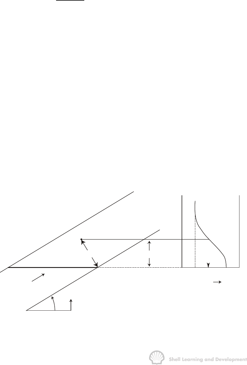
). Consider the static situation during a water drive
shown in fig. 10.5.
WATER
z
A
S = 1 - S
wor
y
X
θ
z = y cos
θ
P
c
S
wc
S
wa
S
w
1 - S
or
∆ρ
gz
OIL
Fig. 10.5 Determination of water saturation as a function of reservoir thickness above
the maximum water saturation plane, S
w
= 1−
−−
−S
or
, of an advancing waterflood

IMMISCIBLE DISPLACEMENT 342
By static it is meant that the downdip water injection is stopped when the maximum
water saturation plane, S
w
= 1 − S
or
, at which P
c
= 0, has just reached point X in the
linear displacement path. If the imbibition capillary pressure curve has a distinct
capillary transition zone, as shown on the right hand side of the diagram, then above
point X the water saturation will be distributed in accordance with the capillary pressure
(capillary rise)-saturation relationship. In particular, the capillary pressure at point A, a
distance y above the base of the reservoir, in the dip-normal direction (normal to the
flow direction), can be calculated as
cw o w
P (S ) = p p = g cos
ργ
θ
−∆ (10.4)
from which the saturation at point A can be determined from the capillary pressure
curve, as shown in fig. 10.5.
Equation (10.4) is referred to, in this text, as the capillary pressure equation expressed,
in this case, in absolute units. In Darcy units, which are used in this chapter to develop
theoretical arguments, the general equation becomes
cw
6
gycos
P(S ) (atm)
1.0133 10
ρθ
∆
=
×
(10.5)
while in the field units defined in table 4.1, which are employed in the exercises
()
cw
P S 0.4335 y cos (psi)
γθ
=∆ (10.6)
where ∆
γ
is the difference between the water and oil specific gravities in the reservoir.
Allowing the S
w
= 1 − S
or
plane to rise incrementally in fig. 10.5 will result in a different
water saturation distribution, in the dip-normal direction, at point X in the displacement
path. This concept is applied in sec. 10.7 in which dynamic displacement is viewed as
a series of static positions of the S
w
= 1 − S
or
plane as the flood moves through the
reservoir, each position leading to a new water saturation distribution dictated by the
capillary pressure-saturation relationship.
b) Displacement generally occurs under conditions of vertical equilibrium
Coats
5
has qualitatively explained the concept of vertical equilibrium by drawing an
analogy with a simple problem in heat conduction. If one were trying to mathematically
describe heat conduction in a thin metal plate, say, 1/8th of an inch thick and with an
area of several square feet, no allowance would be made for the heat distribution
across the thickness of the metal, in which direction thermal equilibrium would be
assumed. Since reservoirs, typically, have dimensions in proportion to those described
for the metal plate, displacement problems can be frequently tackled in a similar
manner. In this case, however, the assumption made is that of fluid potential
equilibrium across the thickness of the reservoir.
The condition for fluid potential equilibrium is simply that of hydrostatic equilibrium,
discussed previously, for which the saturation distribution can be determined as a
function of capillary pressure and, therefore, height, as

IMMISCIBLE DISPLACEMENT 343
()
cw
6
gycos
PS
1.0133 10
ρ
θ
∆
=
×
(10.5)
that is, the fluids are distributed in accordance with capillary-gravity equilibrium. The
vertical equilibrium condition can therefore be interpreted in the following manner.
When, during the displacement of oil by water, the water saturation at any point in the
reservoir increases by a small amount, the new water saturation is instantaneously
redistributed as indicated by equ. (10.5). This means that the vertical velocities of oil
and water, as the two are redistributed in accordance with capillary-gravity equilibrium,
appear to be infinite in comparison with the velocity of fluid movement parallel to the
reservoir bedding planes resulting from the Darcy or viscous forces.
The condition of vertical equilibrium will be promoted by
- a large vertical permeability (k
v
)
- small reservoir thickness (h)
- large density difference between the fluids (∆
ρ
)
- high capillary forces (large capillary transition zone H)
- low fluid viscosities
- low injection rates.
Coats
5,6
has presented two dimensionless groups, relating the above terms, the
magnitudes of which can be used as "rough rules of thumb" for deciding whether
vertical equilibrium conditions prevail in the reservoir. The two cases considered can
be applied when the capillary transition zone is large and also when it is negligible.
These dimensionless groups are not presented in this text since, irrespective of their
magnitude, the only way to check the validity of the vertical equilibrium is by using the
numerical simulation techniques described in sec. 10.10. In any case, when applying
simple, analytical techniques to describe the displacement process one is obliged to
assume that either vertical equilibrium is valid or else the complete opposite, that there
is a total lack of vertical equilibrium. The latter case will apply when, for instance, the
injection rate is so high that the water and oil velocities, parallel to the bedding planes
are much greater than their velocity components in the dip-normal direction. Under
these circumstances the water saturation will be uniformly distributed with respect to
thickness. These two extremes both represent conditions under which the saturation
profile in the dip-normal direction is definable and this facilitates the application of the
analytical techniques described in this chapter. For in-between cases the engineer
must resort to numerical simulation techniques (refer sec. 10.10). It has been found
that the vertical equilibrium condition is approximately satisfied in a great many
reservoirs. Nevertheless, it will be repeatedly stated throughout the remainder of the
chapter precisely when this condition is being assumed, and when not.
IMMISCIBLE DISPLACEMENT 344
c) The displacement is considered as incompressible
This assumption implies that steady state conditions prevail in the reservoir with the
pressure at any point remaining constant. There must, of course, be a pressure
differential between injection and production wells but the variation in the pressure
dependent variables, viscosities and densities, resulting from this differential is ignored.
This type of displacement will occur if
towi
qqq q=+= (10.7)
where
q
t
= total flow rate (r.vol/time)
q
o
= oil"""
q
w
= water"""
q
I
= water injection rate
The assumption is quite realistic since the engineer has control over the displacement
process to a much greater extent than, say, during the volumetric depletion of a
reservoir. Therefore, the wells and surface facilities are usually designed for constant
rate injection/production for it makes little sense to do otherwise. In addition, from a
reservoir engineering point of view, there are definite advantages in maintaining the
pressure at a constant level above that at which the solution gas first becomes mobile
(refer Chapter 3, sec. 5). Because of this assumption the methods described in this
chapter will be equally appropriate for the description of the displacement of oil by gas
at constant pressure with no mass transfer between the phases.
d) The displacement is considered to be linear
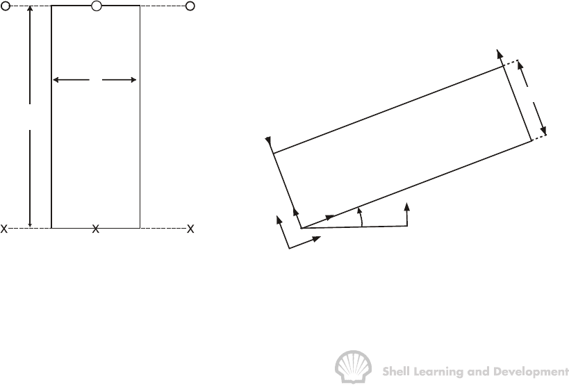
Throughout the chapter displacement will be considered exclusively in a linear
prototype reservoir model, as shown in fig. 10.6.
Injection
Production
w
L
(a) (b)
Z
θ
x
y
h
q
i
q
t
Fig. 10.6 Linear prototype reservoir model, (a) plan view; (b) cross section

IMMISCIBLE DISPLACEMENT 345
The model represents a symmetry element taken from a line drive pattern. The co-
ordinates used in describing displacement in the linear cross section are shown in
fig. 10.6(b). Both the injection and production wells are considered to be perforated
across the entire formation thickness, in the dip-normal direction. No account is taken
of the distortion of the linear flow streamlines (lines of constant fluid potential) in the
vicinity of the wells and saturations are assumed to be uniformly distributed across the
entire width of the block, that is, normal to plane shown in fig. 10.6(b).
The main concern in this chapter is, therefore, to account for the fluid saturation
distributions in the dip-normal direction (y-direction) as the flood moves through the
linear reservoir block. No analytical methods are presented to account for the areal
distribution of saturations in the reservoir. Such methods do exist for regular grid
spacings of injection and production wells and are described in the Craig monograph
1
.
For irregular well spacing, however, the analytical methods are extremely complex and
have largely been superseded by numerical simulation techniques. In fact, one of the
main purposes in using simulators is to determine the areal distribution of oil and water
(or displacing fluid in general) resulting from a flood. This knowledge enables the
engineer to place injection and production wells to gain the maximum recovery. To
provide such results, however, it is necessary that the simulator be informed of what
can be expected to occur in the dip-normal direction, that is, how the fluids will be
distributed in this direction. This information is generally provided as input to the
simulation.
The whole intent of this chapter is, therefore, to describe the physics governing
displacement, as viewed through a linear cross section of the reservoir, which is of vital
concern if the areal distributions of fluids are to be correctly modelled. The chapter
describes, in the first place, displacement in a homogeneous linear section,
secs. 10.3-7, and subsequently extends the methods developed to the description of
displacement in inhomogeneous (layered) reservoirs.
10.3 THE FRACTIONAL FLOW EQUATION
In this, and the following two sections, oil displacement will be assumed to take place
under the so-called diffuse flow condition. This means that fluid saturations at any point
in the linear displacement path are uniformly distributed with respect to thickness. The
sole reason for making this assumption is that it permits the displacement to be
described, mathematically, in one dimension and this provides the simplest possible
model of the displacement process. The one dimensional description follows from the
fact that since the water saturation is uniformly distributed in the dip-normal direction
then so too are the relative permeabilities to oil and water, which are themselves
functions of the water saturation at any point. This means that the simultaneous flow of
oil and water can be modelled using thickness averaged relative permeabilities, along
the centre line of the reservoir, which are also equivalent to relative permeabilities at
any point throughout the thickness.
IMMISCIBLE DISPLACEMENT 346
The diffuse flow condition can be encountered under two extreme physical conditions:
a) when displacement occurs at very high injection rates so that, as described in
sec. 10.2, the condition of vertical equilibrium is not satisfied and the effects of
the capillary and gravity forces are negligible, and
b) for displacement at low injection rates in reservoirs for which the measured
capillary transition zone greatly exceeds the reservoir thickness (H >> h) and the
vertical equilibrium condition applies.
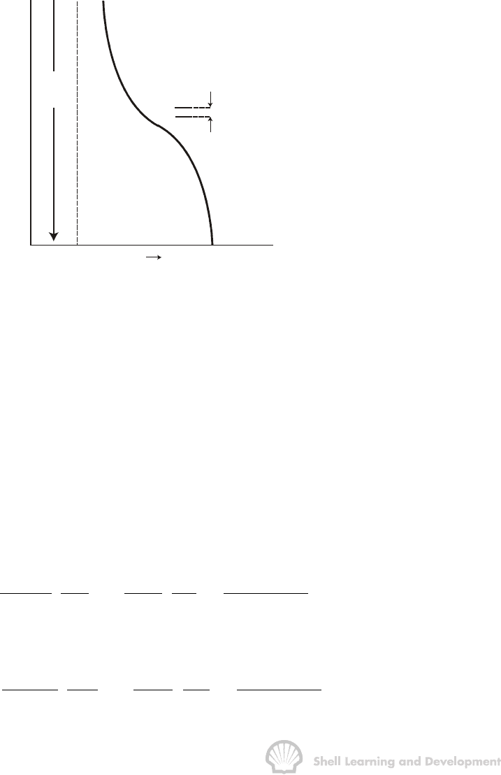
The latter case can be visualized by considering the capillary pressure curve, fig. 10.7.
Since, H >> h then it will appear that the water saturation is, to a first approximation,
uniformly distributed with respect to thickness in the reservoir.
H
P
c
S
w
c
S
w
1 - S
o
r
RESERVOIR THICKNESS h
Fig. 10.7 Approximation to the diffuse flow condition for H>> h
It should also be noted that relative permeabilities are measured in the laboratory
under the diffuse flow condition. This normally results from displacing one fluid by
another, in thin core plugs, at high flow rates
3
. As such, the laboratory, or rock relative
permeabilities, must be regarded as point relative permeabilities which are functions of
the point water saturation in the reservoir. It is, therefore, only when describing
displacement, under the diffuse flow condition, that rock relative permeabilities can be
used directly in calculations since, in this case, they also represent the thickness
averaged relative permeabilities.
Consider then, oil displacement in a tilted reservoir block, as shown in fig. 10.6(b),
which has a uniform cross sectional area A. Applying Darcy's law, for linear flow, the
one dimensional equations for the simultaneous flow of oil and water are
ro o o ro o o
o
6
oo
kk A kk A p g sin
q
xx
1.0133 10
ρρθ
µµ
∂Φ ∂
æö
=− =− +
ç÷
∂∂
×
èø
and
rw w w rw w w
w
6
ww
kk A kk A p g sin
q
xx
1.0133 10
ρρ
θ
µµ
∂Φ ∂
æö
=− =− +
ç÷
∂∂
×
èø

IMMISCIBLE DISPLACEMENT 347
By expressing the oil rate as
q
o
= q
t
- q
w
the subtraction of the above equations gives
oto crw
w
6
rw ro ro
qP
gsin
qA
kk kk kk x 1.0133 10
µµµ
ρ
θ
æö
∂
∆
æö
=− + = + −
ç÷
ç÷
∂×
èø
èø
(10.8)
in which
co
w
Pp
p
xx x
∂∂
∂
=−
∂∂ ∂
the capillary pressure gradient in the direction of flow, and
∆
ρ
=
ρ
w
-
ρ
o
The fractional flow of water, at any point in the reservoir, is defined as
ww
w
ow t
qq
f
qq q
==
+
and substitution of this in equ. (10.8) gives
ro c
6
to
w
row
rw o
kk A P
gsin
1
qx
1.0133 10
f
k
1
k
ρ
θ
µ
µ
µ
∂
∆
æö
+−
ç÷
∂
×
èø
=
+⋅
(10.9)
while, by analogy with equ. (4.18), this equation can be expressed in field units as
3
ro c
to
w
row
rw o
kk A P
1 1.127 10 .4335 sin
qx
f
k
1
k
γ
θ
µ
µ
µ
−
∂
æö
+× − ∆
ç÷
∂
èø
=
+⋅
(10.10)
both of these being fractional flow equations for the displacement of oil by water, in one
dimension.
It is worthwhile considering the influence of the various component parts of this
expression. According to the convention adopted in this text
θ
is the angle measured
from the horizontal to the line indicating the direction of flow. Therefore, the gravity
term ∆
ρ
g sin
θ
/1.0133×10
6
will be positive for oil displacement in the updip direction
(0 <
θ
<
π
), as shown in fig. 10.6(b), and negative for displacement downdip
(
π
<
θ
< 2
π
). As a result, provided all the other terms in equ. (10.9) are the same, the
fractional flow of water for displacement updip is lower than for displacement downdip
since in the former case gravity tends to suppress the flow of water.
IMMISCIBLE DISPLACEMENT 348
The effect of the capillary pressure gradient term is less obvious but can be
qualitatively understood by expressing the gradient as
cc w
w
PdP S
xdS x
∂∂
=⋅
∂∂
(10.11)
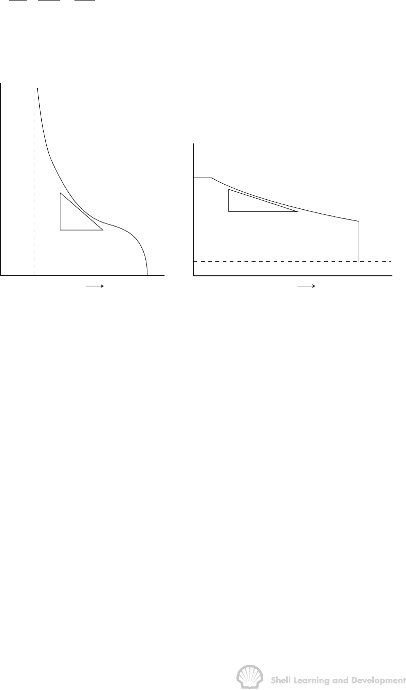
The first term on the right hand side is the slope of the capillary pressure curve,
fig. 10.8(a), and is always negative. The second term is the slope of the water
saturation profile in the direction of flow, a typical profile being shown in fig. 10.8(b).
S
w
c
S
w
1 - S
o
r
S
wc
S
w
1 - S
or
+dS
w
-dP
c
P
c
(a)
-dS
w
+dx
S
wf
(b)
x
Fig. 10.8 (a) Capillary pressure function and; (b) water saturation distribution as a
function of distance in the displacement path
From this it can be seen that ∂S
w
/∂x is also negative. Therefore ∂P
c
/∂x is always
positive and consequently the presence of the capillary pressure gradient term tends to
increase the fractional flow of water. Quantitatively, it is difficult to allow for the capillary
pressure gradient for, although the capillary pressure curve may be available, the water
saturation profile, fig. 10.8(b), is unknown and, as will be shown presently, is the
required result of displacement calculations.
The water saturation distribution shown in fig. 10.8(b), corresponding to the situation
after injecting a given volume of water, may be regarded as typical for the
displacement of oil by water. The diagram shows that there is a distinct flood front, or
shock front, at which point there is a discontinuity in the water saturation which
increases abruptly from S
wc
to S
wf
, the flood front saturation. It is at this shock front
where both derivatives on the right hand side of equ. (10.11) have their maximum
value, which is evident by inspection of fig. 10.8(a) and (b), and therefore ∂P
c
/∂x is also
maximum. behind the flood front there is gradual increase in saturations from S
wf
up to
the maximum value 1 - S
or
. In this region it is normally considered that both dP
c
/dS
w
and ∂S
w
/∂x are small and therefore ∂P
c
/∂x can be neglected in the fractional flow
equation.
For displacement in a horizontal reservoir (sin
θ
= 0), and neglecting, for the moment,
the capillary pressure gradient, the fractional flow equation is reduced to
IMMISCIBLE DISPLACEMENT 349
w
ro
w
rw o
1
f
k
1
k
µ
µ
=
+⋅
(10.12)
Provided the oil displacement occurs at a constant temperature then the oil and water
viscosities have fixed values and equ. (10.12) is strictly a function of the water
saturation, as related through the relative permeabilities. For a typical set of relative
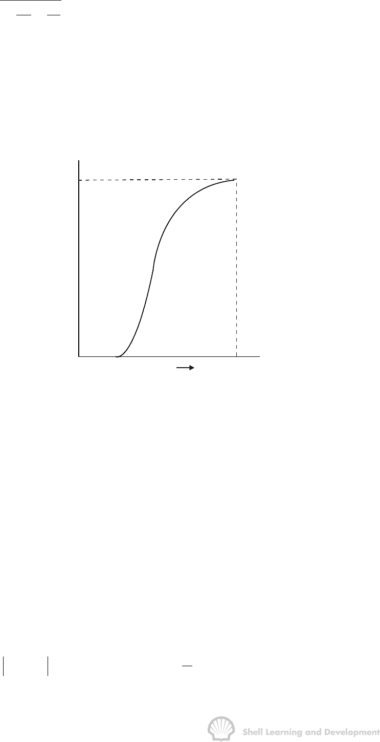
permeabilities, as shown in fig. 4.8, the fractional flow equation, (10.12), usually has
the shape indicated in fig. 10.9, with saturation limits S
wc
and 1 − S
or
, between which
the fractional flow increases from zero to unity. The manner in which the shape of this
curve is influenced by the viscosity ratio of oil to water will be studied in exercise 10.1.
S
w
c
S
w
1 - S
o
r
f
w
f= 1
w
Fig. 10.9 Typical fractional flow curve as a function of water saturation, equ. (10.12)
The fractional flow equation is used to calculate the fraction of the total flow which is
water, at any point in the reservoir, assuming the water saturation at that point is
known. Precisely how to determine when a given water saturation plane reaches a
particular point in the linear system requires the application of the displacement theory
presented in the following section.
10.4 BUCKLEY-LEVERETT ONE DIMENSIONAL DISPLACEMENT
In 1942 Buckley and Leverett presented what is recognised as the basic equation for
describing immiscible displacement in one dimension
7
. For water displacing oil, the
equation determines the velocity of a plane of constant water saturation travelling
through a linear system. Assuming the diffuse flow condition, the conservation of mass
of water flowing through volume element
Adx,
φ
fig. 10.10, may be expressed as
Mass flow rate = Rate of increase of mass
In - Out in the volume element
ww ww ww
xdx
x
qq Adx(S)
t
ρρ φρ
+
∂
−=
∂
(10.13)
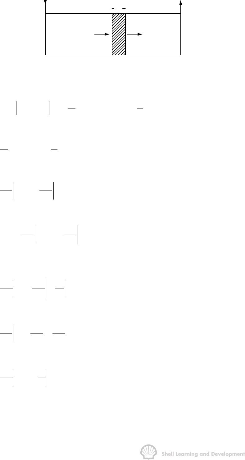
IMMISCIBLE DISPLACEMENT 350
q |
w
ρ
w
x
q |
ρ
ww
x+dx
x
dx
Fig. 10.10 Mass flow rate of water through a linear volume element Adx
φ
or
ww ww ww ww
x
x
qq (q)dxAdx(S)
xt
ρρ ρφρ
∂∂
æö
−+ =
ç÷
∂∂
èø
which can be reduced to
ww ww
(q ) A ( S )
xt
ρφρ
∂∂
=−
∂∂
(10.14)
and for the assumption of incompressible displacement (
ρ
w
≈ constant)
ww
tx
qS
A
xt
φ
∂∂
=−
∂∂
(10.15)
The full differential of the water saturation is
x
ww
w
t
SS
dS dx dt
xt
∂∂
=+
∂∂
and since it is the intention to study the movement of a plane of constant water
saturation, that is, dS
w
= 0, then
w
ww
xtS
SSdx
txdt
∂∂
=−
∂∂
(10.16)
Furthermore,
t
www
t
w
qqS
xSx
æö
∂∂∂
=⋅
ç÷
∂∂∂
èø
(10.17)
and substituting equs. (10.16) and (10.17) in equ. (10.15) gives
w
w
tS
w
qdx
A
Sdt
φ
∂
=
∂
(10.18)
Again, for incompressible displacement, q
t
is constant and, since q
w
= q
t
f
w
, equ. (10.18)
may be expressed as
