Bryan L. Programmable controllers. Theory and implementation
Подождите немного. Документ загружается.

399
CHAPTER
10
The IEC 1131 Standard and
Programming Language
Industrial Text & Video Company 1-800-752-8398
www.industrialtext.com
SECTION
3
PLC
Programming
12 Start_Batch
Batch_Complete12
12 (Start_Batch)
(Batch_Complete)
Batch_Time≥Timeout
12
Level:=Switch_Level
If Level Then Motor:=True
Batch_Time:=t#8M
Tstart (Batch_Time)
Structured
Text
also has a macrostep, which can be considered to be a subroutine or
subprogram chart, but its initial step (IN step 30) is not independent. Chart 2
has a different link representation than charts 1 and 3 between its last step
(12) and its first step (10), meaning that instead of using an arrow to link
these steps, it uses jump instructions. The jump to instruction, programmed
after the last step, uses an X followed by the step number to specify which step
to go to—in this case, step 10. The jump from instruction, which is pro-
grammed before the initial step, uses a Y and the transition number (i.e.,
Y12) to indicate where the jump is from. This Xstep number and Ytransition
number notation is used throughout SFCs to distinguish between step and
transition variables. Some 1131-3 systems use the letters S and T to denote
steps and transitions, respectively, instead of the letters X and Y.
Sequential function charts are classified by levels, depending on how much
detail they show. The SFC representations in Figure 10-29 are level 0 charts,
because they do not specify any of the actions in their steps and do not define
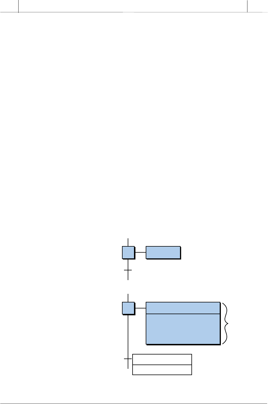
their transitions. Level 1 and level 2 charts (see Figure 10-30) show the actions
associated with their steps. A level 1 chart represents its actions with names,
comments, or descriptions of the control action executed in each step. It may
also describe what occurs in each transition, or it may show the transition
conditions in ST, along with the variables that will trigger them. A level 2
chart actually shows the instructions (in LD, FBD, ST, or IL) that implement
the control action. In addition, it may specify an action description name like
the ones used in level 1 charts; however, this name is shown in parentheses
to avoid confusion with the instruction programming.
Figure 10-30. (a) Level 1 and (b) level 2 sequential function charts.
(a) Level 1
(b) Level 2
400
SECTION
3
PLC
Programming
Industrial Text & Video Company 1-800-752-8398
www.industrialtext.com
CHAPTER
10
The IEC 1131 Standard and
Programming Language
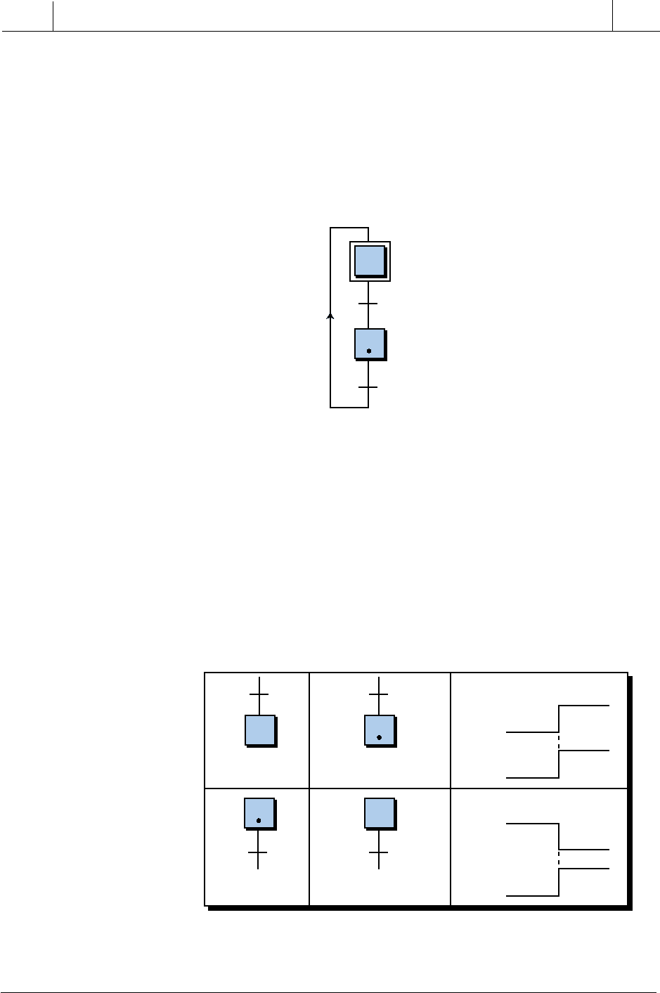
Each step and transition in an SFC has an ON status or condition if it is
active and an OFF status if it is inactive. A dot, or token, indicates the ON/
OFF status of a step or transition. As illustrated in Figure 10-31, the dot in the
step 11 block indicates that the step is active, meaning that the status of X11
is ON. Some manufacturers refer to the ON/OFF status of a step or transition
as its Boolean activity or Boolean attribute because of the TRUE/FALSE
nature of the signal activity.
10
11
10
11
Condition X10
Condition Y10
Condition X11
Condition Y11
Figure 10-31. The dot in step 11 indicates that it is ON.
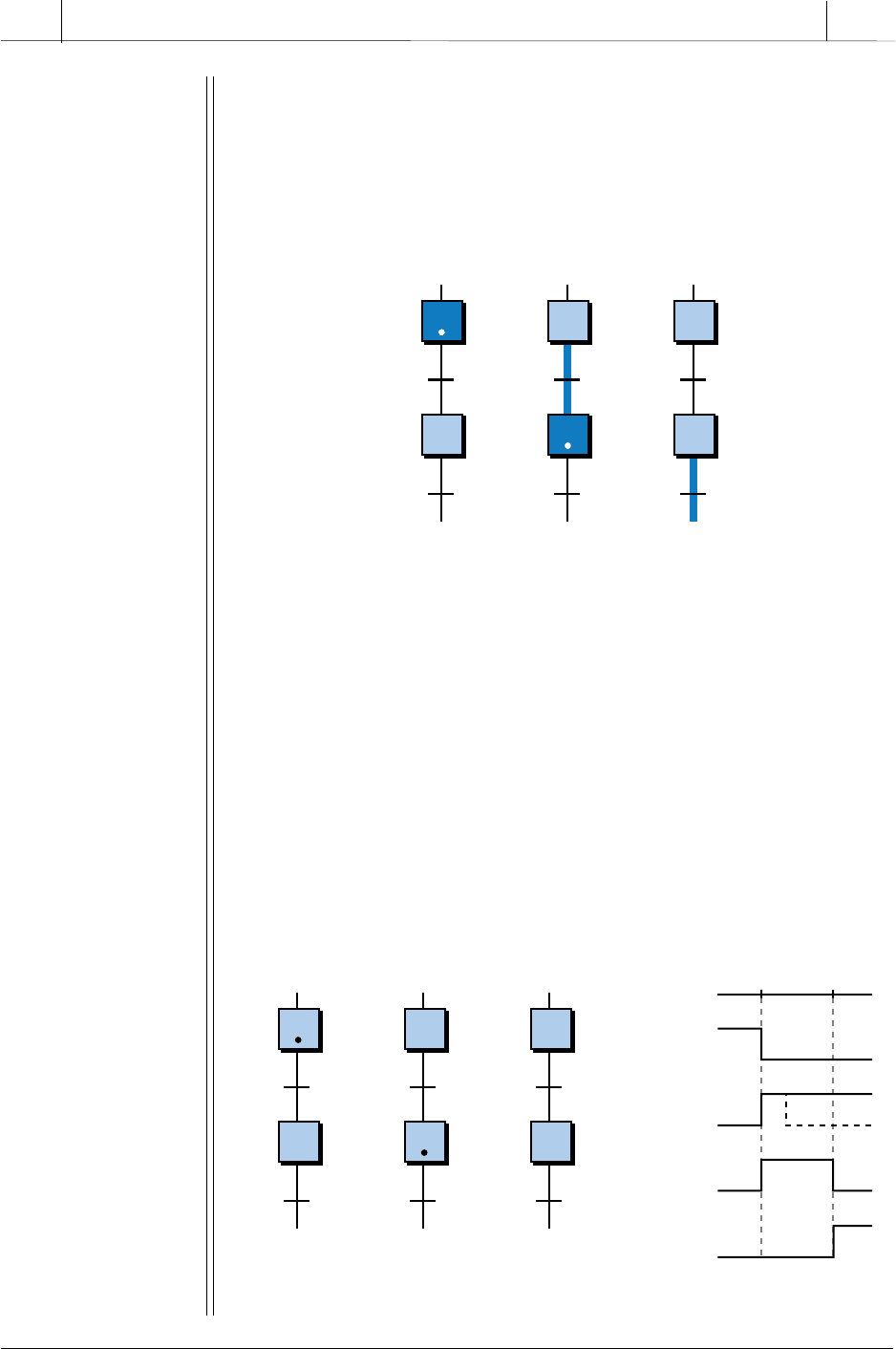
Figure 10-32a illustrates a step being activated by a transition, while Figure
10-32b shows a step being deactivated by a transition. As shown in the timing
diagram in Figure 10-32a, Y9 and X10 are both FALSE during time a1
because the Y9 transition has not occurred and, therefore, has not passed the
token to step 10 (i.e., activated it). Once a condition or variable triggers
transition Y9 (turns it ON), step 10 becomes active and the step condition
X10 becomes TRUE. In Figure 10-32b, the timing diagram shows that step
12 is active (X12 is ON) during time b1 and becomes deactivated the moment
transition Y12 turns ON at time b2.
12
12 12
10
9
12
10
9
a1
—Step
not active
a2
—Step is active
after transition
b1
—Step
is active
b2
—Step is not
active after transition
(a)
(b)
1
0
1
0
Y9
X10
a1
Time:
a2
1
0
1
0
X12
Y12
b1
Time:
b2
Figure 10-32. (a) An inactive step activated by a transition and (b) an active step
deactivated by a transition.
401
CHAPTER
10
The IEC 1131 Standard and
Programming Language
Industrial Text & Video Company 1-800-752-8398
www.industrialtext.com
SECTION
3
PLC
Programming
E
XAMPLE
10-4
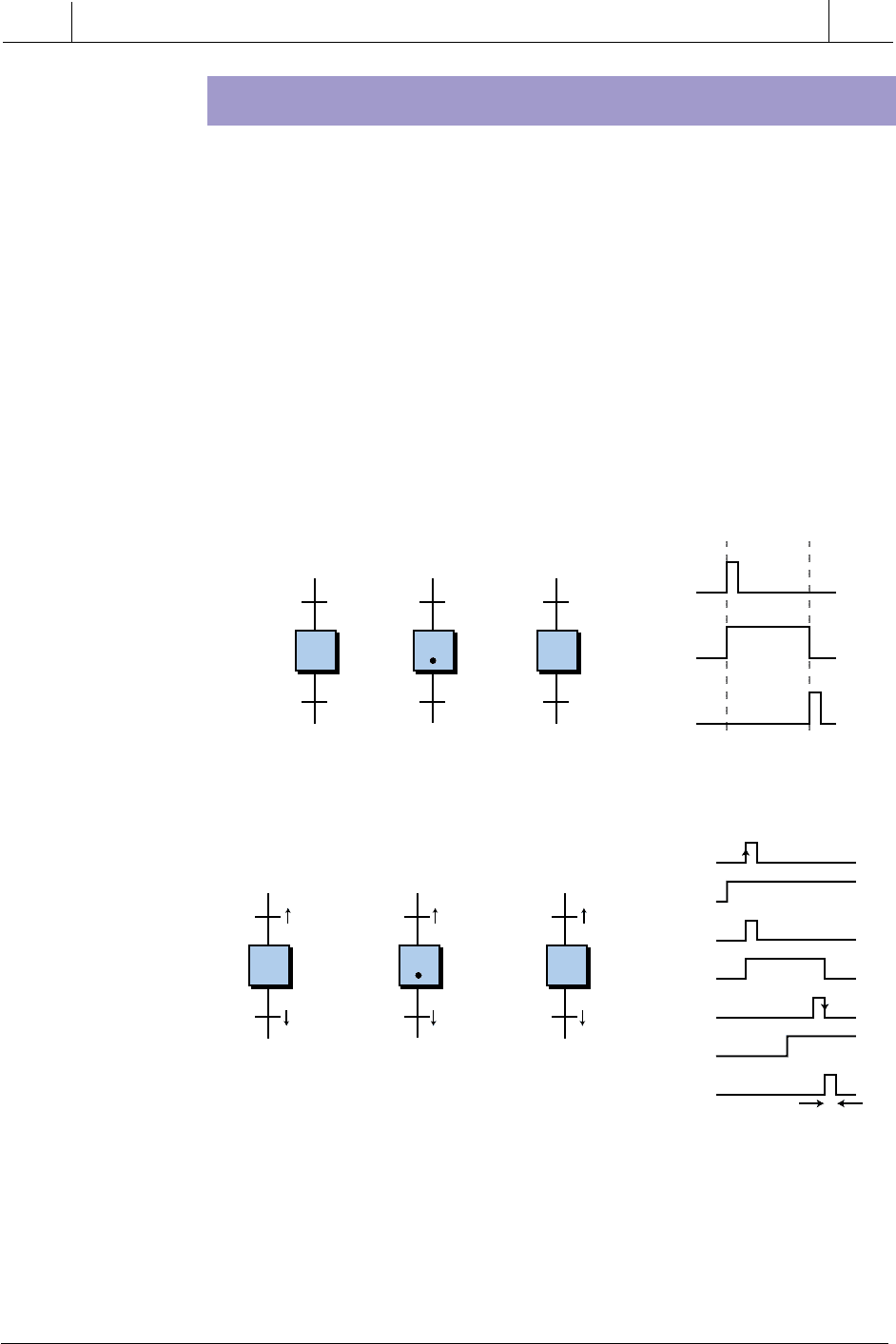
Figure 10-33 shows an SFC in three different stages: (a) step 3
active, (b) step 4 active after being triggered by transition IN_1,
and (c) step 4 turned OFF by the triggering of transition IN_2.
Using a timing diagram, graphically illustrate the status of the
steps (Xs) and the transitions (Ys) in each of these three phases.
3
4
3
4
IN_1
IN_2
3
4
3
4
IN_1
IN_2
3
4
3
4
IN_1
IN_2
Figure 10-33. Control being passed through an SFC.
S
OLUTION
Figure 10-34 shows the timing diagrams for each of the three stages
in Figure 10-33. When step 3 is active (with token), X3 is ON and its
action will be executed. Once the transition IN_1 occurs (Y3 goes from
OFF to ON), the token passes to step 4 for execution of its action; thus,
X4 becomes ON. Step 4 will remain active (ON) until transition IN_2
(Y4) becomes TRUE, at which time, the control token will pass to the
next step. Note that a transition does not need to remain ON once the
token is passed to the next step down the chart. For example, the
transition Y3 signal turned OFF immediately after passing the token to
step 4; the dotted line in the timing diagram indicates this.
3
4
3
4
IN_1
IN_2
3
4
3
4
IN_1
IN_2
3
4
3
4
IN_1
IN_2
(a) (b) (c)
1
0
1
0
1
0
X3
Y3
X4
1
0
Y4
abc
Figure 10-34. Timing diagram for the chart in Figure 10-33.
(a)
Step 3 ON
(b)
Step 4 ON
(c)
Step 4 OFF
(a)
(b)
(c)
402
SECTION
3
PLC
Programming
Industrial Text & Video Company 1-800-752-8398
www.industrialtext.com
CHAPTER
10
The IEC 1131 Standard and
Programming Language
TRANSITIONS
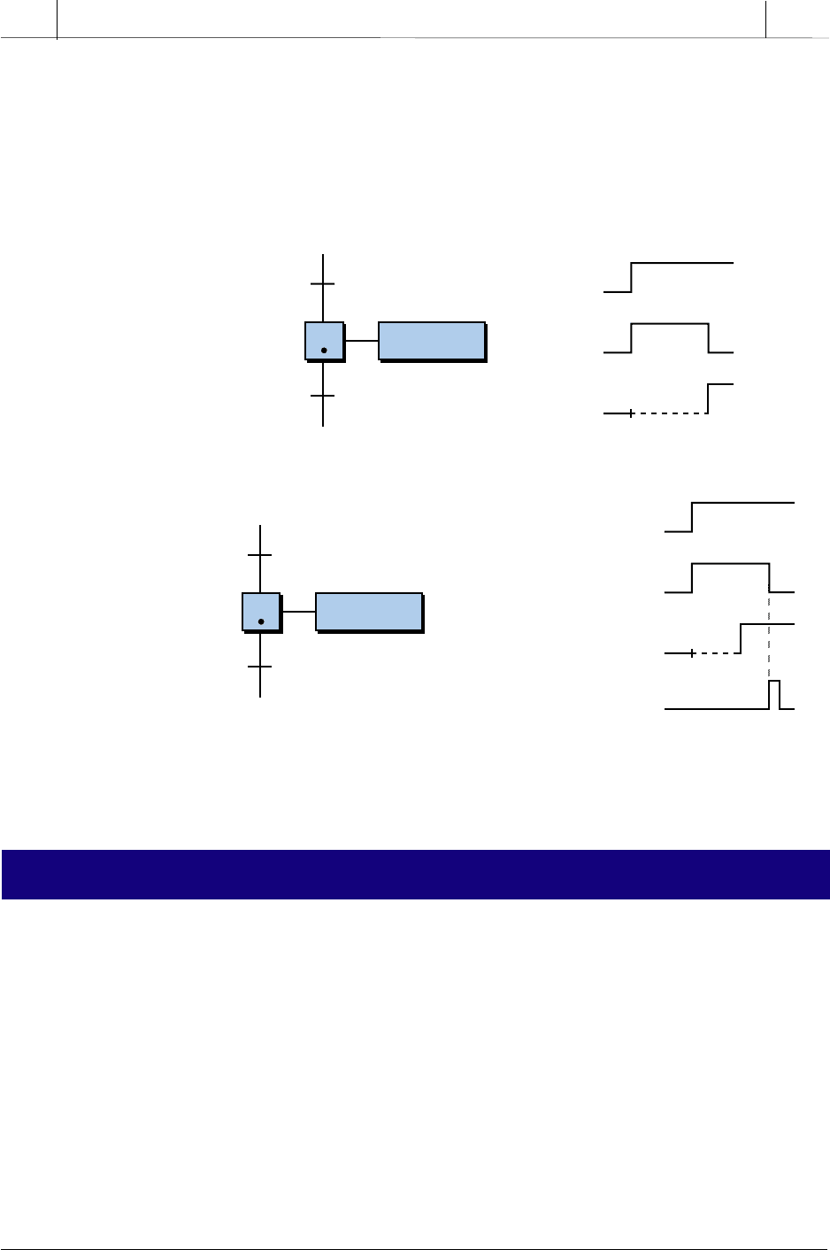
As described in the previous example, the triggering condition of a transition
can be a momentary pulse that quickly goes from OFF to ON to OFF. Figure
10-35 shows two pulse transitions, Y9 and Y10, which activate and deactivate
step 10. These transitions can be programmed so that either the leading edge
or the trailing edge of the pulse triggers the move to the next step. In Figure
10-36, transition 9 is programmed as a leading-edge transition using an AND
condition. In this configuration, the turning ON of signal A will initiate the
transition to step 10 as long as signal B is already ON. Transition 10 is also
programmed using an AND condition; however, it is a trailing-edge transi-
tion. This means that, as long as signal D is active, the turning OFF of signal
C will turn OFF step 10. This type of transition is similar to leading- and
trailing-edge transitionals in ladder diagrams.
10
9
10
9
10 10
1
0
1
0
1
0
Y9
X10
Y10
Before Active
Step
10
9
10
After Active
Step
Active
Step
Figure 10-35. Example of momentary transition pulses.
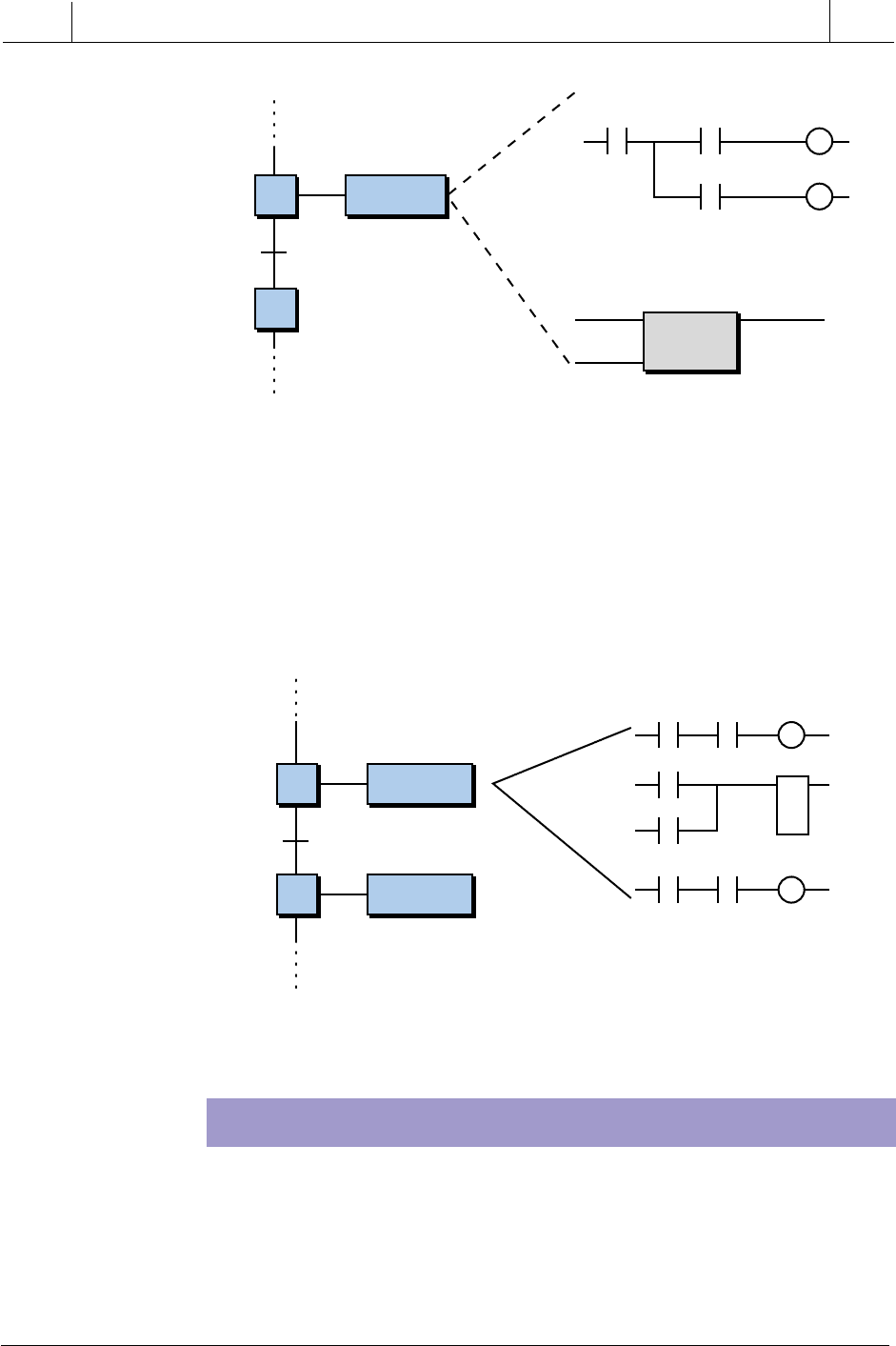
A timing element can be included in a transition to determine how long a
step will be active. For instance, step 11 in Figure 10-37a will be active and
its action executed for a period of 100 seconds because transition Y11
includes a timer set for 100 seconds. A timing transition instruction can also
Figure 10-36. Leading- and trailing-edge transition pulses.
10
9
10
9
10 10
1
0
A
1
0
B
1
0
Y9
1
0
X10
1
0
C
1
0
D
1
0
Y10
10
9
10
A
AND
B
C
AND
D
A
AND
B
C
AND
D
A
AND
B
C
AND
D
One Scan
403
CHAPTER
10
The IEC 1131 Standard and
Programming Language
Industrial Text & Video Company 1-800-752-8398
www.industrialtext.com
SECTION
3
PLC
Programming
be combined with Boolean logic combinations (AND, OR, NOT) and
IF...THEN instructions. For example, in Figure 10-37b, the control program
in the action in step 11 will lower a part down in a punch press and wait for
at least 10 seconds. However, it will also wait for the Down_Pos input to
be TRUE before deactivating the step 11 action and moving control to the
next step.
Figure 10-37. (a) A timed transition and (b) a timed transition combined with a
Boolean logic function.
10-3 SEQUENTIAL FUNCTION CHART PROGRAMMING
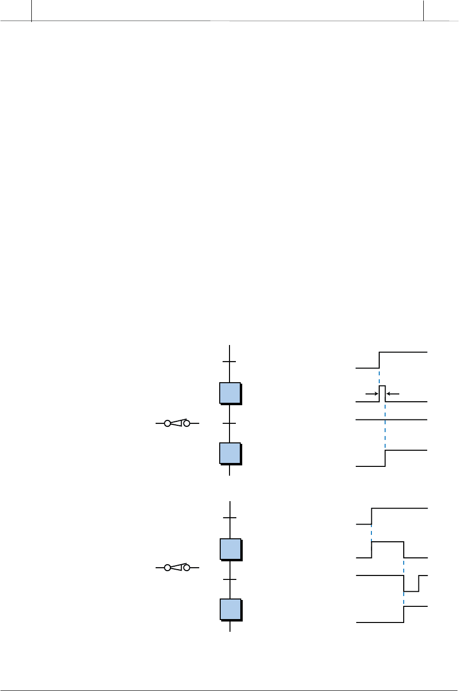
The signal that triggers a transition may be the result of an external variable
or a step’s output. For example, in Figure 10-38, step 10’s action instructions
(in this case, an LD, ST, and FBD control sequence) control the status of the
transition Time_Up, which will move control execution to the next step.
When step 10 becomes active, the Mix_Start action begins, and the processor
scans all the I/O in the action and executes the program as described by the
action’s instructions. If Mix_Rdy is TRUE (in the LD part of the action),
then the motor will be turned on for 30 seconds as specified by the timer.
Once the 30 seconds have elapsed, the timer’s Boolean output variable
Time_Up, which is defined as an internal Bool variable, will be TRUE,
initiating the transition to the next step.
11
Mix_Batch
TMR/X11/100 sec11
10
1
0
1
0
1
0
Y10
X11
Y11
100 sec
(a)
11
Lower_Part
TMR/X11/10 sec
AND Down_Pos11
10
(b)
1
0
1
0
1
0
Y10
X11
1
0
Down_Pos
Y11
10 sec
(a)
(b)
404
SECTION
3
PLC
Programming
Industrial Text & Video Company 1-800-752-8398
www.industrialtext.com
CHAPTER
10
The IEC 1131 Standard and
Programming Language
Transitions can also be logically combined with other instructions, most
commonly with the structured text language. For instance, in Figure 10-39,
the transition from step 12 to 13 will occur if the command Set_OK inside the
action of step 12 (labeled as Action_1) is TRUE and the signal Level_Switch
is TRUE. Set_OK is an internal output, while Level_Switch is a direct input
signal connected to a PLC input module.
10
Mix_Start
11
Level_OK Flow_OK
Level_2_OK Mix_Rdy
Set_OK
TMR
Time_Up
IF Mix_Rdy THEN Motor:=TRUE
IN OUT
PT ET
Motor Time_Up
30 Sec
Figure 10-38. Action output as a trigger for a transition.
12
ACTION_1
13
ACTION_2
LD Program
Set_OK
Set_OK AND Level_Switch
Figure 10-39. Combination of an internal output and an external variable as
a transition.
PROGRAMMING NORMALLY CLOSED TRANSITIONS
As explained in the previous chapter, a normally closed input device should
be programmed as normally open in a PLC for it to operate as a normally
closed device. The reason for this is safety. When programmed as normally
open, the device will lose continuity and turn OFF if its connection to the
input module is cut. This provides fail-safe operation. This same criteria
405
CHAPTER
10
The IEC 1131 Standard and
Programming Language
Industrial Text & Video Company 1-800-752-8398
www.industrialtext.com
SECTION
3
PLC
Programming
applies for a normally closed device in a PLC using IEC 1131-3 program-
ming—all normally closed devices should be programmed as normally open,
regardless of the language used.
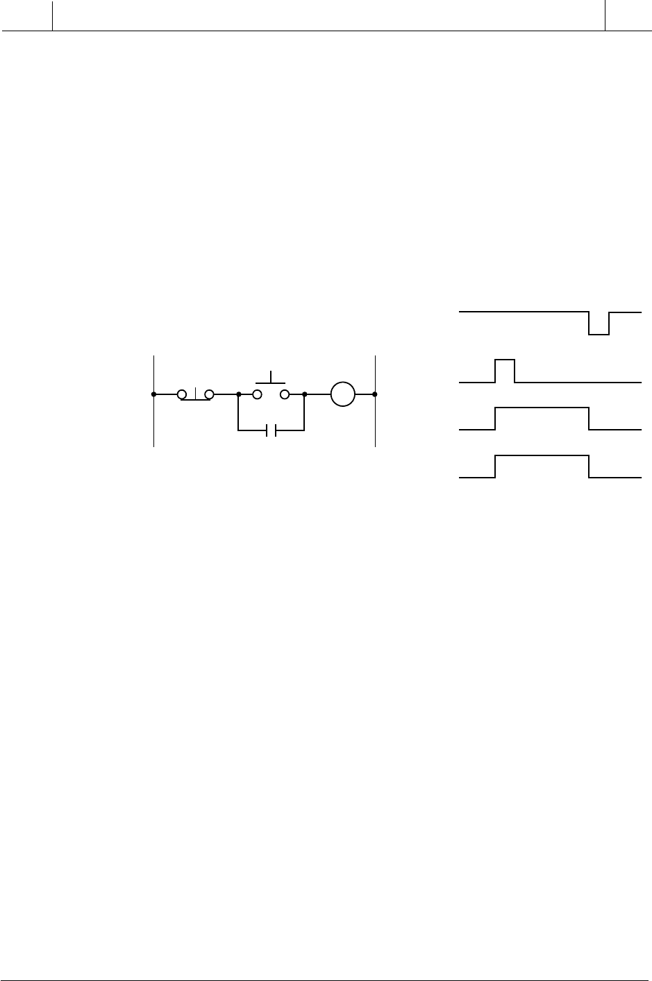
Normally closed devices must also be programmed carefully when used as
triggering variables in an SFC transition. If the normally closed device is not
actuated (e.g., a normally closed limit switch is closed), the transition from
one step to the next one will be in one scan. Let’s take a closer look. Figure
10-40a illustrates a part of a simple chart in which the normally closed limit
switch LS_1 is used to trigger the transition from step 10 to step 11. Note that
the timing diagram, which represents the Boolean activity, indicates that
LS_1 is ON when not activated. Thus, the transition from step 10 to 11 will
occur as soon as step 10 is active (one scan). To trigger the transition from
step 10 to step 11 upon the activation of LS_1 (normally closed LS_1
opening), the transition must be programmed as NOT LS_1. This way, if
LS_1 opens, the NOT LS_1 instruction will trigger the transition. Note
that in Figure 10-40b, the limit switch opened momentarily to trigger the
transition to step 11. It is a good idea to study timing diagrams when
programming a normally closed device to observe the required behavior of
the transition.
Figure 10-40. The transition from step 10 to step 11 will (a) occur in one scan
unless (b) transition 10 is programmed as NOT LS_1.
10
11
LS_1
Trans_9
10
9
1
0
1
0
1
0
Y9
X10
1
0
X11
Y10
10
11
NOT LS_1
Trans_9
10
9
1
0
1
0
1
0
Y9
X10
1
0
X11
Y10
One Scan
(a)
(b)
406
SECTION
3
PLC
Programming
Industrial Text & Video Company 1-800-752-8398
www.industrialtext.com
CHAPTER
10
The IEC 1131 Standard and
Programming Language
Figure 10-41 illustrates a simple start/stop hardwired motor circuit and its
timing diagram. When the momentary normally open start push button is
pressed and the normally closed stop push button is not pressed, the motor will
be ON and its motor contacts M1-1 will seal the start push button, meaning
that the motor will remain ON until the stop PB is pressed. When the stop PB
is pressed, the circuit will lose continuity and the motor will turn OFF.
Logically speaking, as shown in the timing diagram in Figure 10-41, the
motor will be ON if both the start PB (wired as normally open) and the stop
PB (wired as normally closed) are ON (1), in other words, start is ON
(Start=1) and stop is NOT OFF (Stop=1). Therefore, the logic expression that
will turn M1 ON is M1=Start AND Stop.
Figure 10-41. A hardwired start/stop motor circuit and its timing diagram.
L1 L2
Stop PB
Start PB
M1-1
M1
1
0
1
0
1
0
Stop
Start
M1-1
1
0
Motor
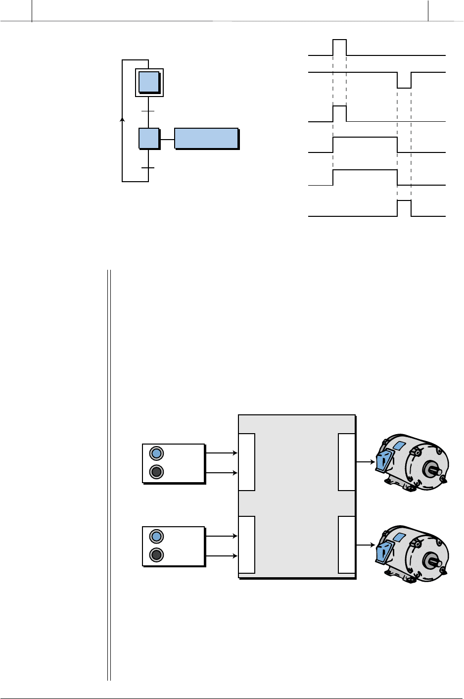
Figure 10-42 illustrates the SFC implementation of the hardwired circuit in
Figure 10-41, along with its timing diagram. In the SFC, the logic expression
that triggers transition 1 (Start_AND_Stop) is the same logic expression that
turns motor M1 ON in the hardwired circuit, but without interlock. The
program does not require interlocking between the push buttons because it
does not need to remember that the start PB was pressed to keep the motor
ON. Once the momentary start PB is pressed, step 1 (no action) transitions
to step 2, where the action turns ON the motor and keeps it in that state. The
program will turn the motor OFF as soon as transition Y2 is triggered,
meaning that the NOT_Stop condition occurred. As soon as the stop push
button is pressed (see the timing diagram in Figure 10-42), transition Y2 will
be satisfied and the control token will be transferred from step X2 (motor ON)
to step X1, turning off the action in X2 and, consequently, motor M1.
This logic expression indicates that M1 will be ON if the start PB is pushed
and the stop PB is not pushed (normally closed). However, the logic
expression does not provide latching capabilities, meaning that if the start PB
is pushed once and released, the motor M1 will not stay ON. As we will
explain shortly, in the SFC implementation of this M1 logic expression, the
latching or interlocking of the M1 logic expression is not required.
407
CHAPTER
10
The IEC 1131 Standard and
Programming Language
Industrial Text & Video Company 1-800-752-8398
www.industrialtext.com
SECTION
3
PLC
Programming
1
0
1
0
1
0
Start
Stop
X2
1
0
Y1
1
0
Motor
1
0
Y2
1
2
Motor:=True
1
2
Start_
AND
_Stop
NOT_Stop
Figure 10-42. SFC implementation of the hardwired circuit in Figure 10-41.
EXAMPLE 10-5
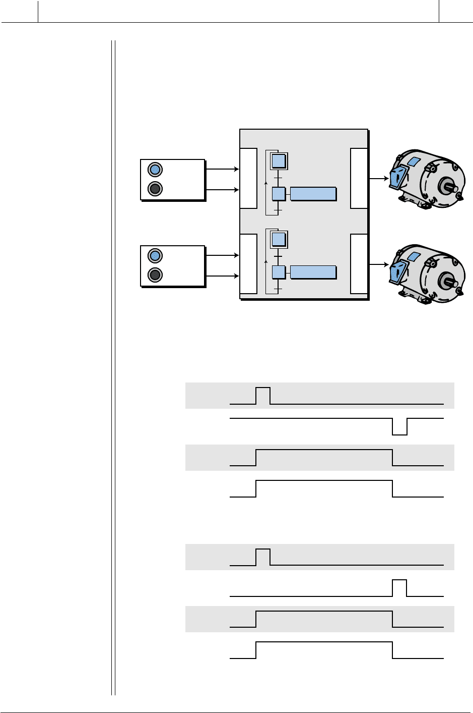
Figure 10-43 illustrates a block diagram of PLC input devices used
to control the ON/OFF state of two motors, Motor_1 and Motor_2.
Assume that the pair of start/stop push buttons used with Motor_1
has a normally open start and a normally closed stop, while the start/
stop push buttons used with Motor_2 are both normally open (for
illustration purposes). Using SFCs, implement two independent pro-
grams in the PLC system that will control the start/stop sequence of the
two motors.
Figure 10-43. Block diagram of a program controlling two motors.
SOLUTION
Figure 10-44 shows the SFC charts for the two push button stations,
while Figure 10-45 shows the corresponding timing diagrams. Note
that the logic for the transitions that turn the motors ON is different. For
Motor 1
Start 1
Stop 1
N.O.
N.C.
Motor 2
Start 2
Stop 2
N.O.
N.O.
PLC
I
n
p
u
t
O
u
t
p
u
t
I
n
p
u
t
O
u
t
p
u
t
Motor_1
Motor_2
408
SECTION
3
PLC
Programming
Industrial Text & Video Company 1-800-752-8398
www.industrialtext.com
CHAPTER
10
The IEC 1131 Standard and
Programming Language
Motor_1, the logic takes into consideration that the normally closed
stop push button is wired as normally closed. For Motor_2, the logic
shows that the stop push button is a normally open push button wired
as open to an input module.
Figure 10-44. SFC charts for Motor_1 and Motor_2.
Figure 10-45. Timing diagrams for (a) Motor_1 and (b) Motor_2.
1
0
1
0
1
0
Start_1
Stop_1
X2
1
0
M_1
1
0
1
0
1
0
Start_2
Stop_2
X4
1
0
M_2
X2=Start_1
AND Stop_1
X4=Start_2
AND NOT Stop_2
Motor 1
Start 1
Stop 1
N.O.
N.C.
Motor 2
Start 2
Stop 2
N.O.
N.O.
PLC
I
n
p
u
t
O
u
t
p
u
t
I
n
p
u
t
O
u
t
p
u
t
Motor_1
Motor_2
3
4
Motor_2:=True
3
4
Start_2
AND NOT
Stop_2
Stop_2
1
2
Motor_1:=True
1
2
Start_1
AND
Stop_1
Not_Stop_1
Chart 1
Chart 2
(a)
(b)
