Bryan L. Programmable controllers. Theory and implementation
Подождите немного. Документ загружается.

379
CHAPTER
10
The IEC 1131 Standard and
Programming Language
Industrial Text & Video Company 1-800-752-8398
www.industrialtext.com
SECTION
3
PLC
Programming
EXAMPLE 10-1
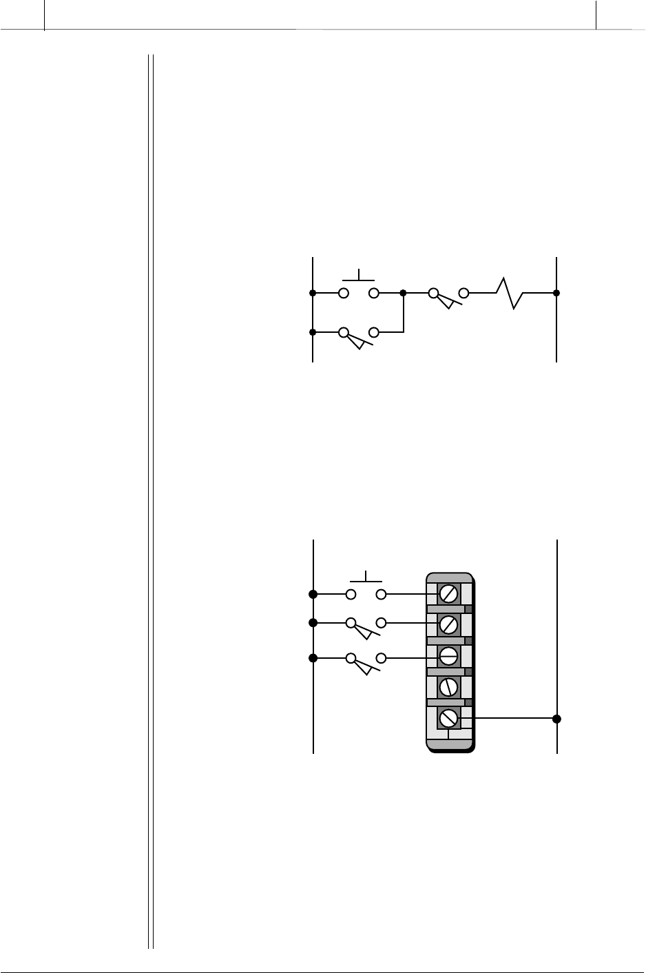
Implement the Boolean variable declaration (variable names and
variable types) for the input devices shown in Figure 10-2a for use in
a control program. Assume that the controller being used follows the
rack-slot-terminal address configuration (e.g., rack 0, slot 0, terminal
3 is address 003). Figure 10-2b shows the wiring to the input module.
Figure 10-2. (a) A traditional hardwired circuit and (b) its wiring diagram.
0
1
2
3
L1
Rack 0
Slot 0
L2
PB1
LS1
LS2
L1 L2
PB1 SOL
LS2
LS1
PLC Input Module Wiring
Hardwired Circuit
Description of Inputs
C
PB1: Used to manually start conveyor sequence
LS1: Detects parts in automatic start
LS2: Detects a no-jam condition
S
OLUTION
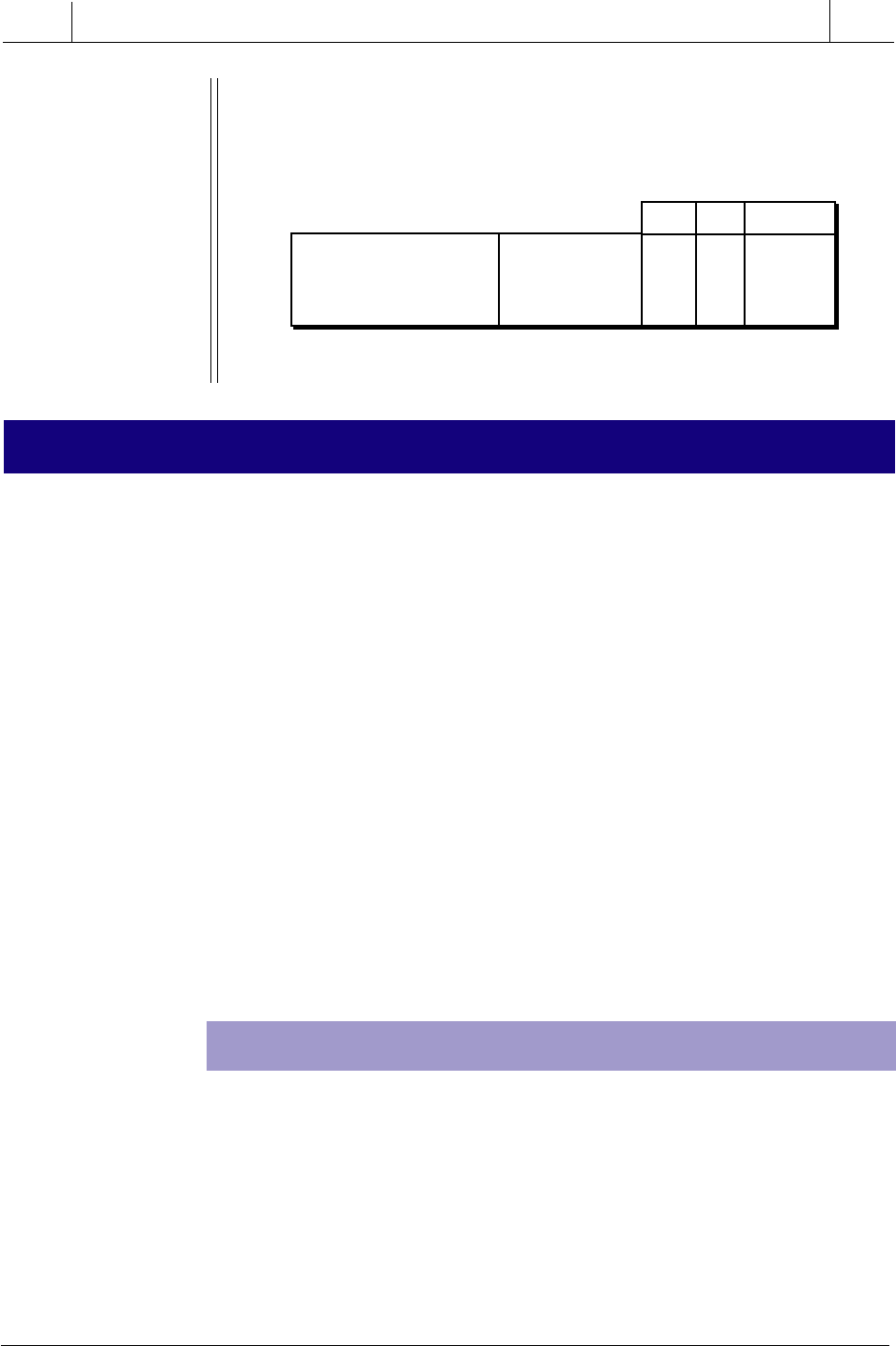
Figure 10-3 shows a sample variable declaration for this example.
All of the input devices are discrete; therefore, they are specified
as Boolean variables. PB1 is named MAN_START_PB, LS1 is named
AUTO_PART_Detect, and LS2 is named NO_JAM_Detect.
(a)
(b)
380
SECTION
3
PLC
Programming
Industrial Text & Video Company 1-800-752-8398
www.industrialtext.com
CHAPTER
10
The IEC 1131 Standard and
Programming Language
Figure 10-3. Boolean variable declaration.
10-2 IEC 1131-3 PROGRAMMING LANGUAGES
While the IEC 1131-3 programming standard provides great new potential
for programmable controller users, it is actually based on the relay ladder
logic that has been inherent in PLCs since their inception. The IEC 1131-3 is
based on the ladder logic used in PLC ladder diagrams (including functional
blocks) because of its simplicity of use, representation, and to some extent,
programmability. The IEC 1131-3, however, reduces the need for complex
interlocking circuits within PLC ladder diagram circuits. It enhances the
languages previously used in programmable controllers and incorporates
them with a powerful framework—sequential function charts—making in-
terlocking, interpretation of the control program, and implementation of the
control system much easier for both the programmer and the final user of the
system. With this in mind, let’s briefly discuss the four languages that are
used with the IEC 1131-3 standard—ladder diagrams, function block dia-
grams, instruction list, and structured text—along with sequential function
charts. Note that, when programming in the IEC 1131-3, any of these
languages may be used either alone or as a group, with or without sequential
function charts. In Section 10-4, we will list all available IEC 1131-3
programming instructions.
LADDER DIAGRAMS (LD)
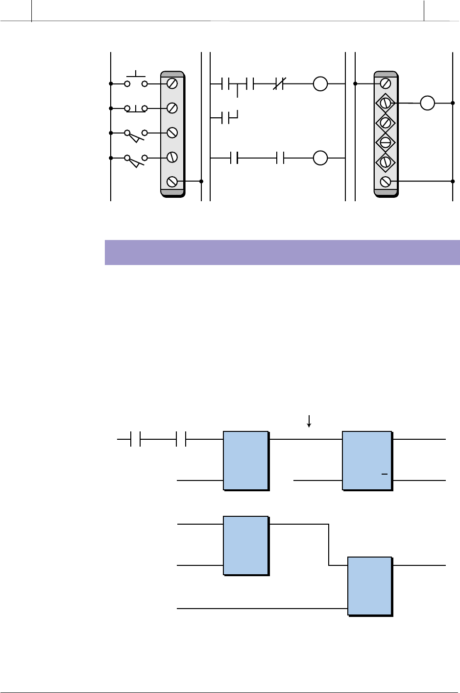
Ladder diagram language (LD) uses a standardized set of ladder program-
ming symbols to implement control functions. This type of programming
language is essentially the one that has always been available in PLCs (see
Figure 10-4). Users familiar with current PLC ladder diagrams can use the
same programming techniques and methods when using this language in an
IEC 1131-3 environment. However, as we will explain later, interlocking
ladder diagram programming is much easier to implement in the IEC 1131-
3 format due to the use of sequential function charts.
Note that these variable names, which can be chosen by the user,
describe the operational functions of the input devices.
MAN_START_PB
AUTO_PART_Detect
NO_JAM_Detect
Bool
Bool
Bool
0
0
0
0
0
0
0
1
2
Input Variable Name Variable Type Rack Slot Terminal
Address Location
381
CHAPTER
10
The IEC 1131 Standard and
Programming Language
Industrial Text & Video Company 1-800-752-8398
www.industrialtext.com
SECTION
3
PLC
Programming
Figure 10-4. Ladder diagram representation of a PLC program.
FUNCTION BLOCK DIAGRAM (FBD)
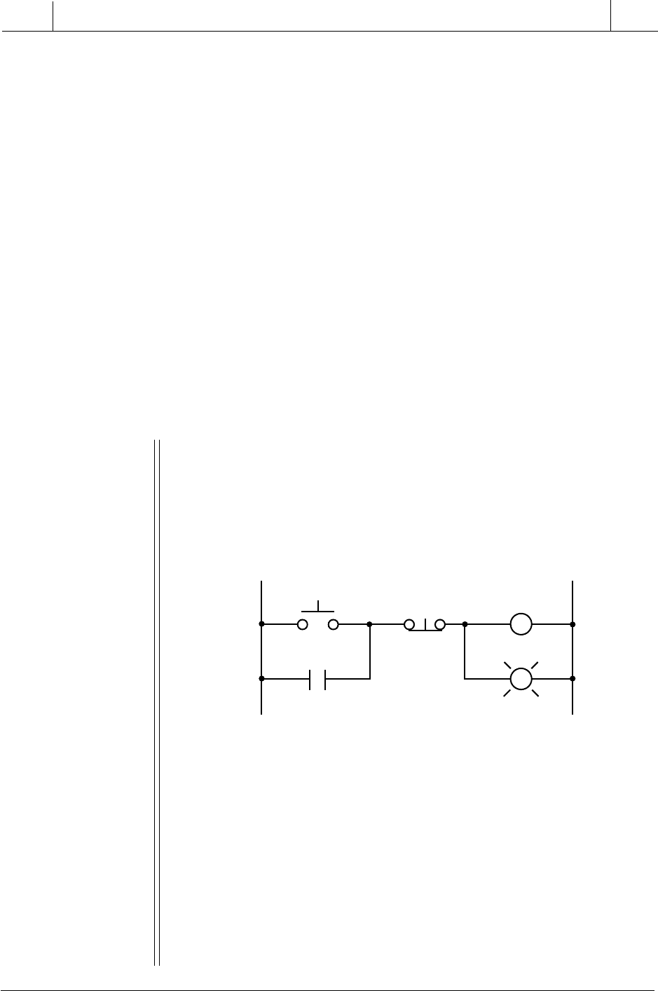
Function block diagram (FBD) is a graphical language that allows the user
to program elements (e.g., PLC function blocks) in such a way that they
appear to be wired together like electrical circuits. Figure 10-5 illustrates this
type of function block diagram configuration. Some IEC 1131-3 systems use
logic symbols to represent the function blocks. Note that the output logic of
the block in Figure 10-5 does not incorporate an output coil because the
output is represented by the variable assigned to the output of the block. This
LS_Stop LS_OK
TMR
PR AR
SQ
RQ
Time_Value
Set/Reset
Dwell
AND
(&)
POS_RT
AT_TOP
SETDwell
Cont_Cycle
Reset_Sys Stop_Cycle
Move_Up
OR
(
^
)
Section of a control program using a timer,
set/reset, AND, and OR function blocks
Output variable of timer (Dwell) becomes
the input to the set/reset block
Figure 10-5. Function block diagram language.
01
02
03
04
L1 L2
Start
Start Stop Done Drill_Motor
LS_Reach
LS_Reach LS_Top Done
LS_Top
Stop
C
01
02
03
04
C
L1
L1 L2
Drill_Motor
Drill_Motor
382
SECTION
3
PLC
Programming
Industrial Text & Video Company 1-800-752-8398
www.industrialtext.com
CHAPTER
10
The IEC 1131 Standard and
Programming Language
variable can be used throughout the program in other instructions and as a
control output through the address mapping performed during variable
declaration. The user may still choose to use an output coil representation if
desired; however, it will only be allowed in the last (right-most) block. The
FBD language uses both standard and vendor-specified function blocks. The
block functions typically used with the IEC 1131 standard include, for the
most part, the block functions discussed in Chapter 9.
In addition to standard and vendor-specified functions, the IEC 1131-3
allows users to “build” their own function blocks according to control
program requirements. This is referred to as encapsulating a block function.
The advantage of creating user-defined blocks is that they can be built using
other function blocks, instruction list, or structured text programming with
or without ladder diagram instructions. This allows great flexibility in
function block programming. Encapsulation also lets the user store a newly
created block in a library and use it as many times as needed in the program,
just like any other function block. Example 10-2 illustrates how ladder
diagrams can be used to create a custom function block.
L1 L2
Start
M1
PL1
M1
Stop
M
Figure 10-6. Start/stop circuit.
EXAMPLE 10-2
Illustrate how the hardwired start/stop circuit shown in Figure 10-6 can
be implemented using ladder diagrams in a custom-built function
block to turn ON motor M1 and pilot light PL1.
SOLUTION
Figure 10-7 illustrates the ladder diagram equivalent of the
hardwired start/stop circuit. Note that there are two rungs for the two
outputs and that both the input and output variables are specified
with the same names that they had in the hardwired circuit.
To implement this simple ladder diagram as a function block, it must
be programmed or stored in an encapsulated block (see Figure 10–
8a). The final function block will look like the diagram shown in Figure
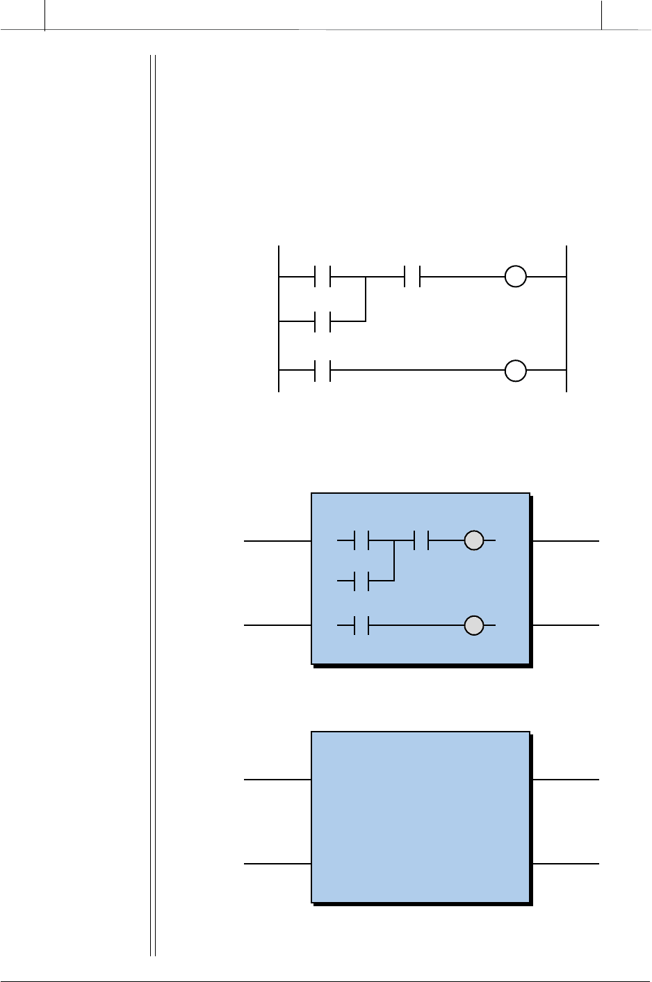
383
CHAPTER
10
The IEC 1131 Standard and
Programming Language
Industrial Text & Video Company 1-800-752-8398
www.industrialtext.com
SECTION
3
PLC
Programming
M1
Stop M1Start
M1
PL1
PLC Program
Figure 10-7. Ladder diagram equivalent of the circuit in Figure 10-6.
Motor
Stop MotorStart
Motor
Pilot_Light
START
STOP
MOTOR
PILOT_LIGHT
START
STOP
MOTOR
PILOT_LIGHT
Start/Stop Block
Figure 10-8. (a) Encapsulated ladder diagram and (b) start/stop block function.
10-8b. Note that the inputs to the start/stop block will act according
to the logic used to program the block. If the driving logic to the start
input is ON, then the motor and light will turn ON. If the stop input
is ON, then both the motor and light outputs will be OFF. The two
input variables (the START and STOP commands), as well as the
two output variables (the MOTOR and PILOT_LIGHT signals), are
Boolean variables.
(a)
(b)
384
SECTION
3
PLC
Programming
Industrial Text & Video Company 1-800-752-8398
www.industrialtext.com
CHAPTER
10
The IEC 1131 Standard and
Programming Language
The flexibility of custom block creation is enhanced by the fact that the user
can build custom blocks using ladder diagrams or any of the other IEC
1131-3 languages (IL and ST). Also, custom blocks can be used in conjunc-
tion with other standard or vendor-specified function blocks. This allows the
programmer to create very powerful function blocks that can be integrated
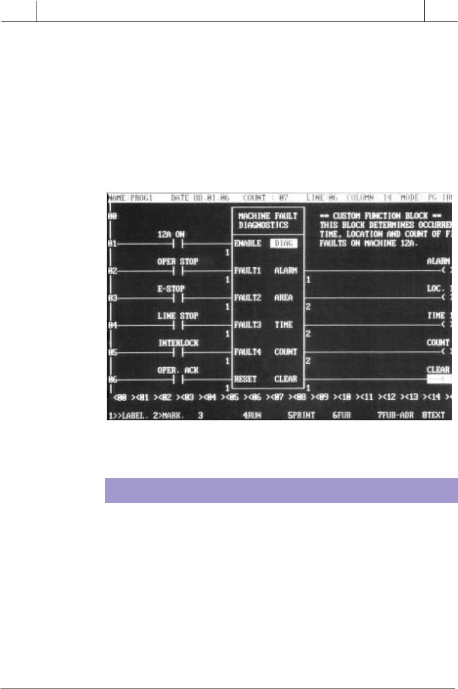
into any ladder diagram or function block diagram. Figure 10-9 shows a
custom block instruction that was created in a B&R Industrial Automation
PLC using their instruction list language.
Figure 10-9. Custom function block from B & R Industrial Automation.
Courtesy of B & R Industrial Automation, Roswell, GA
Instruction list (IL) is a low-level language similar to the machine or
assembly language used with microprocessors (see Figure 10-10). This type
of language is useful for small applications, as well as applications that
require speed optimization of the program or a specific routine in the
program. As mentioned earlier, IL can be used to create custom function
blocks. A typical application of IL might involve the initialization to zero
(i.e., reset) of the accumulated value registers for all the timers in a control
program. As shown in Figure 10-11, a programmer could use IL to create a
function block that would load the contents of all the timers’ accumulated
registers (AR) with a value of zero.
INSTRUCTION LIST (IL)
385
CHAPTER
10
The IEC 1131 Standard and
Programming Language
Industrial Text & Video Company 1-800-752-8398
www.industrialtext.com
SECTION
3
PLC
Programming
Figure 10-10. Example of the machine/assembly language used in microprocessors.
Figure 10-11. Instruction list custom function block that resets timer values to zero.
LD
AND
ANDN
ST
b1
b2
b3
b0
(*current result:=TRUE*)
(*current result:=b1 AND b2*)
(*current result:=b1 AND b2 AND NOT b3*)
(*b0:=current result*)
Instructions Comments
Note: The current result is held in a result register.
The last instruction stores the result register as
the variable b0.
ZERO:=Ø
LD
ST
ST
ST
ST
ZERO
TIMER_AR_1
TIMER_AR_2
TIMER_AR_3
TIMER_AR_4
Start: LD RESET_TIMER
JMPNC Prog_End
(*Load reset condition*)
(*If not TRUE, jump to end of program*)
(*Go back to start*)Prog_End: JMP Start
(*If TRUE, continue and reset all AR in timers*)
(*Timer_AR_1 is the address of the first
timer’s accumulated register*)
Reset_Timer
Address of TMR1 AR
Address of TMR2 AR
Address of TMR3 AR
Address of TMR4 AR
TMR_RESET_FBD
Reset_Timer
Timer_AR_1
Timer_AR_2
Timer_AR_3
Timer_AR_4
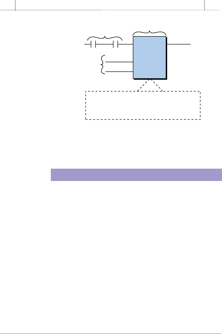
TMR1 AR is the address of the first timer’s accumulated register. In the
FBD, this address is known as Timer_AR_1 so that the IL program can
interpret it. The result of the IL program will be that the values in the
specified accumulated registers will be reset to 0. The variable
Reset_Timer will trigger the block and start the IL instruction. The IL
routine will cycle back to start while the block is enabled by the
Reset_Timer variable being ON. There are also ways to “pulse” just
once through the program so that the instruction is executed only one
time, if enabled.

386
SECTION
3
PLC
Programming
Industrial Text & Video Company 1-800-752-8398
www.industrialtext.com
CHAPTER
10
The IEC 1131 Standard and
Programming Language
STRUCTURED TEXT (ST)
Structured text (ST) is a high-level language that allows structured pro-
gramming, meaning that many complex tasks can be broken down into
smaller ones. ST resembles a BASIC- or PASCAL-type computer language
(see Figure 10-12), which uses subroutines to perform different parts of the
control function and passes parameters and values between the different
sections of the program. Like LD, FBD, and IL, the structured text language
utilizes variable definitions to identify input and output field devices and any
other internally created variables that are used in the program. ST also
supports iterations, such as WHILE...DO and REPEAT...UNTIL, as well as
other conditional executions, such as IF...THEN...ELSE. Moreover, struc-
tured text language supports Boolean operations (AND, OR, etc.) and a
variety of specific data, such as time of day information.
IF Manual AND NOT Alarm THEN
Level:=Manual_Level;
Mixer:=Start AND NOT Reset
ELSE_IF Other_Mode THEN
Level:=Max_Level;
ELSE Level:=(Level_Indic × 100)/Scale;
END_IF;
Figure 10-12. Example of a BASIC-like computer program.
The structured text language is extremely useful for executing routines like
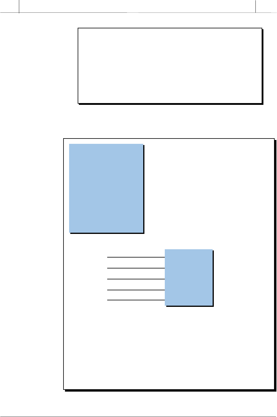
report generation, where English-like instructions explain what is being done.
Remember that ST can be used to encapsulate, or create, a function block that
will perform a certain task when triggered by the control logic (see Figure 10-
13). This function block routine can be used repeatedly throughout the
control program.
Some PLC manufacturers enhance the standard features of ST by using it to
integrate real-time force I/O and monitoring I/O (analog and digital) data in
the same manner as a standard PLC would using ladder diagrams. For
example, an ST instruction such as FORCE Variable_One would force
Variable_One to be ON regardless of any other conditions, as long as
Variable_One is Boolean. If the variable was analog, the instruction may be
FORCE Variable_One = 5000; in which case, the value of the analog variable
would be set to 5000 during the forcing.
387
CHAPTER
10
The IEC 1131 Standard and
Programming Language
Industrial Text & Video Company 1-800-752-8398
www.industrialtext.com
SECTION
3
PLC
Programming
Finished
Conditions
to trigger report
Custom Report
Function Block
Temp_Var
Press_Var
Variable_1
Report
Variable_2
Values
passed from
variables
IF REPORT THEN
Message “Target Temperature:”:=Variable_1
Message “Actual Temperature:”:=Variable_2
END_IF
Figure 10-13. Report generation function block created using structured text.
SEQUENTIAL FUNCTION CHARTS (SFC)
Structured text programming is particularly suited to applications involving
data handling, computational sorting, and intensive mathematical applications
utilizing floating-point values. ST is also the best language for implementing
artificial intelligence (AI) computations, fuzzy logic, and decision making.
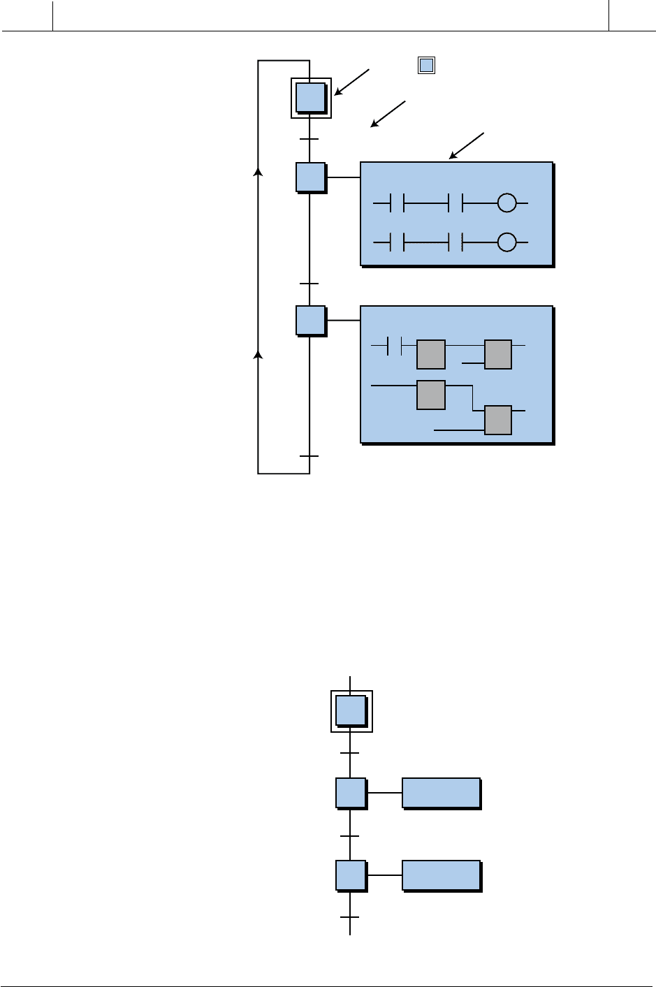
Sequential functional chart, or SFC, is a graphical “language” that provides
a diagrammatic representation of control sequences in a program. Basically,
sequential function chart is a flowchart-like framework that can organize the
subprograms or subroutines (programmed in LD, FBD, IL, and/or ST) that
form the control program. SFC is particularly useful for sequential control
operations, where a program flows from one step to another once a condition
has been satisfied (TRUE or FALSE).
The SFC programming framework contains three main elements that orga-
nize the control program:
• steps
• transitions
• actions
A step is a stage in the control process. For example, the mixing application
shown in Figure 10-14 has three steps—the initial step, the mixing step, and
the emptying step. When the control program receives an input, it will execute
each of these steps starting with step 1. Each step may or may not have an
action associated with it. An action is a set of control instructions prompting
388
SECTION
3
PLC
Programming
Industrial Text & Video Company 1-800-752-8398
www.industrialtext.com
CHAPTER
10
The IEC 1131 Standard and
Programming Language
1
2
3
1
2
3
LS_Reach
IF Temp_1≥100
PB_Return
Action_2
Action_3
Figure 10-15. Transitions in a sequential function chart.
the PLC to execute a certain control function during that step. An action
may be programmed using any one of the four IEC 1131-3 languages. After
the PLC executes a step/action, it must receive a transition before it will
proceed to the next step. A transition can take the form of a variable input,
a result of a previous action, or a conditional IF statement (e.g., IF
Temp_1≥100). So, for the application shown in Figure 10-15, the PLC will
execute action 2 only after step 1 receives a valid input and transition 1
1
2
3
1
2
3
Trans_1
Trans_2
Trans_3
Mix_Batch (Ladder Diagram)
Empty_Batch (FBD)
STEP ( means initial step)
TRANSITION
ACTION
Figure 10-14. Sequential function chart of a mixing process.
