Brennen Ch.E. Fundamentals of Multiphase Flow
Подождите немного. Документ загружается.

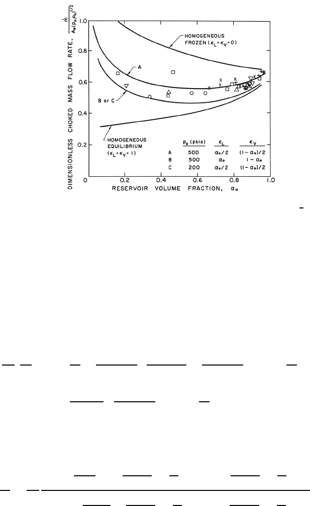
Figure 9.9. The dimensionless choked mass flow rate, ˙m/A
∗
(p
o
ρ
o
)
1
2
,plot-
ted against the reservoir vapor volume fraction, α
o
,forwater/steammix-
tures. The data shown is from the experiments of Maneely (1962) and
Neusen (1962) for 100 → 200 psia (+), 200 → 300 psia (×), 300 → 400
psia (), 400 → 500 psia (), 500 → 600 psia ()and> 600 psia (∗).
The theoretical lines use g
∗
=1.67, η =0.73, g
V
=0.91, and f
V
=0.769
for water.
analysis of the last section. Since the approximation ρ ≈ ρ
L
(1 − α)wasused
in deriving both equation 9.30 and equation 9.41, we may eliminate α/(1 −
α) from these equations to obtain the velocity, u,intermsofp/p
o
:
ρ
L
p
o
u
2
2
=1−
p
p
o
+
1
(1 − k
V
)
α
o
(1 − α
o
)
+
k
L
p
−η
o
(k
V
− η)
1 −
p
p
o
1−k
V
−
1
(1 − η)
k
L
p
−η
o
(k
V
− η)
1 −
p
p
o
1−η
(9.44)
To find the relation for the critical pressure ratio, p
∗
/p
o
,thevelocity,u,
must equated with the sonic velocity, c, as given by equation 9.31:
c
2
2
=
p
ρ
L
1+
α
o
1−α
o
+ k
L
p
−η
o
(k
V
−η)
p
o
p
k
V
−
k
L
p
−η
o
(k
V
−η)
p
o
p
η
2
2
k
V
α
o
(1−α
o
)
+
k
L
p
−η
o
(k
V
−η)
p
o
p
k
V
− η
k
L
p
−η
o
(k
V
−η)
p
o
p
η
(9.45)
Though algebraically complicated, the equation that results when the
right-hand sides of equations 9.44 and 9.45 are equated can readily be solved
239
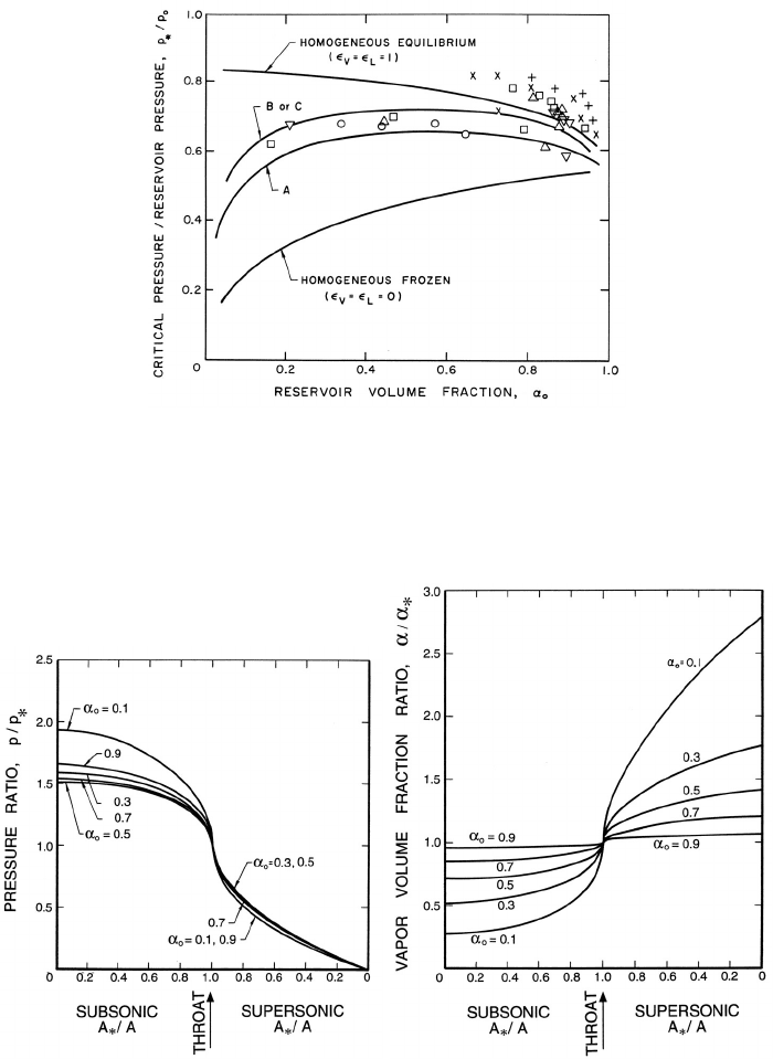
Figure 9.10. The ratio of critical pressure, p
∗
, to reservoir pressure, p
o
,
plotted against the reservoir vapor volume fraction, α
o
,forwater/steam
mixtures. The data and the partially frozen model results are for the same
conditions as in figure 9.9.
Figure 9.11. Left: Ratio of the pressure, p, to the critical pressure, p
∗
,and
Right: Ratio of the vapor volume fraction, α, to the critical vapor volume
fraction, α
∗
, as functions of the area ratio, A
∗
/A, for the case of water with
g
∗
=1.67, η =0.73, g
V
=0.91, and f
V
=0.769.
240
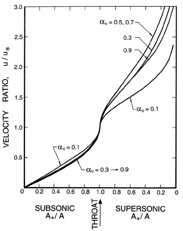
Figure 9.12. Ratio of the velocity, u, to the critical velocity, u
∗
,asa
function of the area ratio for the same case as figure 9.11.
numerically to obtain the critical pressure ratio, p
∗
/p
o
, for a given fluid and
given values of α
o
, the reservoir pressure and the interacting fluid fractions
L
and
V
(see section 9.3.3). Having obtained the critical pressure ratio,
the critical vapor volume fraction, α
∗
, follows from equation 9.30 and the
throat velocity, c
∗
, from equation 9.45. Then the dimensionless choked mass
flow rate follows from the same relation as given in equation 9.43.
Sample results for the choked mass flow rate and the critical pressure
ratio are shown in figures 9.9 and 9.10. Results for both homogeneous frozen
flow (
L
=
V
= 0) and for homogeneous equilibrium flow (
L
=
V
=1)are
presented; note that these results are independent of the fluid or the reservoir
pressure, p
o
. Also shown in the figures are the theoretical results for various
partially frozen cases for water at two different reservoir pressures. The
interacting fluid fractions were chosen with the comment at the end of section
9.3.3 in mind. Since
L
is most important at low vapor volume fractions (i.e.,
for bubbly flows), it is reasonable to estimate that the interacting volume
of liquid surrounding each bubble will be of the same order as the bubble
volume. Hence
L
= α
o
or α
o
/2 are appropriate choices. Similarly,
V
is
most important at high vapor volume fractions (i.e., droplet flows), and it
is reasonable to estimate that the interacting volume of vapor surrounding
241
each droplet would be of the same order as the droplet volume; hence
V
=
(1 − α
o
)or(1− α
o
)/2 are appropriate choices.
Figures 9.9 and 9.10 also include data obtained for water by Maneely
(1962) and Neusen (1962) for various reservoir pressures and volume frac-
tions. Note that the measured choked mass flow rates are bracketed by the
homogeneous frozen and equilibrium curves and that the appropriately cho-
sen partially frozen analysis is in close agreement with the experiments, de-
spite the neglect (in the present model) of possible slip between the phases.
The critical pressure ratio data is also in good agreement with the partially
frozen analysis except for some discrepancy at the higher reservoir volume
fractions.
It should be noted that the analytical approach described above is much
simpler to implement than the numerical solution of the basic equations
suggested by Henry and Fauske (1971). The latter does, however, have the
advantage that slip between the phases was incorporated into the model.
Finally, information on the pressure, volume fraction, and velocity else-
where in the duct (p/p
∗
, u/u
∗
,andα/α
∗
) as a function of the area ratio
A/A
∗
follows from a procedure similar to that used for the noncondensable
case in section 9.5.1. Typical results for water with a reservoir pressure,
p
o
, of 500 psia and using the partially frozen analysis with
V
= α
o
/2and
L
=(1− α
o
)/2 are presented in figures 9.11 and 9.12. In comparing these
results with those for the two-component mixture (figures 9.7 and 9.8) we
observe that the pressure ratios are substantially smaller and do not vary
monotonically with α
o
. The volume fraction changes are smaller, while the
velocity gradients are larger.
9.5.3 Condensation shocks
In the preceding sections we investigated nozzle flows in which the two com-
ponents or phases are present throughout the flow. However, there are also
important circumstances in expanding supersonic gas or vapor flows in which
the initial expansion is single phase but in which the expansion isentrope
subsequently crosses the saturated vapor/liquid line as sketched in figure
9.13. This can happen either in single component vapor flows or in gas flows
containing some vapor. The result is that liquid droplets form in the flow
and this cloud of droplets downstream of nucleation is often visible in the
flow. Because of their visibility these condensation fronts came to be called
condensation shocks in the literature. They are not, however, shock waves
for no shock wave processes are involved. Indeed the term is quite misleading
242
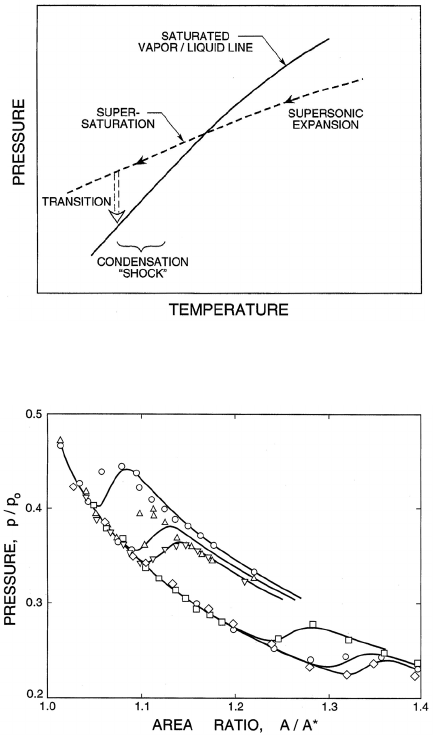
Figure 9.13. The occurence of condensation during expansion in a diffuser.
Figure 9.14. Experimental pressure profiles through condensation fronts
in a diffuser for six different initial conditions. Also shown are the corre-
sponding theoretical results. From Binnie and Green (1942) and Hill (1966).
since condensation fronts occur during expansion rather than compression
in the flow.
The detailed structure of condensation fronts and their effect upon the
overall flow depends upon the nucleation dynamics and, as such is outside
the scope of this book. For detailed analyses, the reader is referred to the
reviews of Wegener and Mack (1958) and Hill (1966). Unlike the inverse
phenomenon of formation of vapor bubbles in a liquid flow (cavitation -
see section 5.2.1), the nucleation of liquid droplets during condensation is
governed primarily by homogeneous nucleation rather than heterogeneous
243
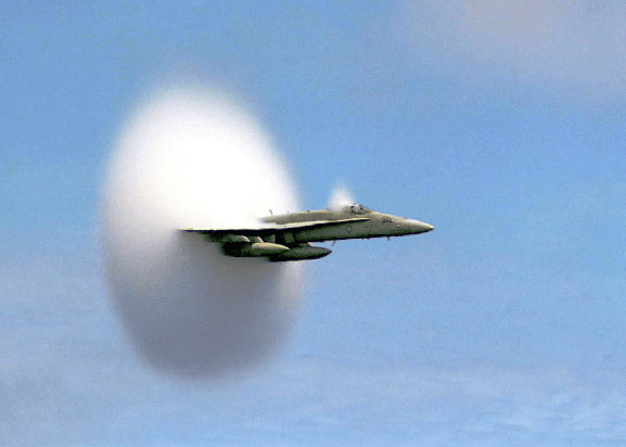
Figure 9.15. Condensation fronts in the flow around a transonic F/A-18
Hornet operating in humid conditions. U.S. Navy photograph by Ensign
John Gay.
nucleation on dust particles. In a typical steam expansion 10
15
/cm
3
nuclei
are spontaneously formed; this contrasts with the maximum credible concen-
tration of dust particles of about 10
8
/cm
3
and consequently homogeneous
nucleation predominates.
Homogeneous nucleation and the growth of the droplets require time and
therefore, as indicated in figure 9.13, an interval of supersaturation occurs
before the two-phase mixture adjusts back toward equilibrium saturated
conditions. The rate of nucleation and the rate of growth of these droplets
will vary with circumstances and may result in an abrupt or gradual de-
parture from the isentrope and adjustment to saturated conditions. Also, it
transpires that the primary effect on the flow is the heating of the flow due
to the release of the latent heat of vaporization inherent in the formation of
the droplets (Hill 1966). Typical data on this adjustment process is shown in
figure 9.14 that includes experimental data on the departure from the initial
isentrope for a series of six initial conditions. Also shown are the theoretical
predictions using homogeneous nucleation theory.
For more recent work computing flows with condensation fronts the reader
is referred, by way of example, to Delale et al. (1995). It also transpires that
flows in diffusers with condensation fronts can generate instabilities that
have no equivalent in single phase flow (Adam and Schnerr 1997).
244
Condensation fronts occur in both internal and external flows and can
often be seen when aircraft operate in humid conditions. Figure 9.15 is a
classic photograph of a US Navy F/A-18 Hornet traveling at transonic speeds
in which condensation fronts can be observed in the expansion around the
cockpit cowling and downstream of the expansion in the flow around the
wings. Moreover, the droplets can be seen to be re-evaporated when they
are compressed as they pass through the recompression shock at the trailing
edge of the wings.
245
10
FLOWS WITH BUBBLE DYNAMICS
10.1 INTRODUCTION
In the last chapter, the analyses were predicated on the existence of an effec-
tive barotropic relation for the homogeneous mixture. Indeed, the construc-
tion of the sonic speed in sections 9.3.1 and 9.3.3 assumes that all the phases
are in dynamic equilibrium at all times. For example, in the case of bubbles
in liquids, it is assumed that the response of the bubbles to the change in
pressure, δp, is an essentially instantaneous change in their volume. In prac-
tice this would only be the case if the typical frequencies experienced by the
bubbles in the flow are very much smaller than the natural frequencies of
the bubbles themselves (see section 4.4.1). Under these circumstances the
bubbles would behave quasistatically and the mixture would be barotropic.
However, there are a number of important contexts in which the bubbles are
not in equilibrium and in which the non-equilibrium effects have important
consequences. One example is the response of a bubbly multiphase mixture
to high frequency excitation. Another is a bubbly cavitating flow where the
non-equilibrium bubble dynamics lead to shock waves with substantial noise
and damage potential.
Inthischapterwethereforeexaminesomeflowsinwhichthedynamics
of the individual bubbles play an important role. These effects are included
by incorporating the Rayleigh-Plesset equation (Rayleigh 1917, Knapp et
al. 1970, Brennen 1995) into the global conservation equations for the mul-
tiphase flow. Consequently the mixture no longer behaves barotropically.
Viewing these flows from a different perspective, we note that analyses of
cavitating flows often consist of using a single-phase liquid pressure distri-
bution as input to the Rayleigh-Plesset equation. The result is the history of
the size of individual cavitating bubbles as they progress along a streamline
in the otherwise purely liquid flow. Such an approach entirely neglects the
246
interactive effects that the cavitating bubbles have on themselves and on the
pressure and velocity of the liquid flow. The analysis that follows incorpo-
rates these interactions using the equations for nonbarotropic homogeneous
flow.
10.2 BASIC EQUATIONS
In this chapter it is assumed that the ratio of liquid to vapor density is
sufficiently large so that the volume of liquid evaporated or condensed is
negligible. It is also assumed that bubbles are neither created or destroyed.
Then the appropriate continuity equation is
∂u
i
∂x
i
=
η
(1 + ηv)
Dv
Dt
(10.1)
where η is the population or number of bubbles per unit volume of liquid
and v(x
i
,t) is the volume of individual bubbles. The above form of the
continuity equation assumes that η is uniform; such would be the case if
the flow originated from a uniform stream of uniform population and if
there were no relative motion between the bubbles and the liquid. Note also
that α = ηv/(1 + ηv) and the mixture density, ρ ≈ ρ
L
(1 − α)=ρ
L
/(1 + ηv).
This last relation can be used to write the momentum equation 9.2 in terms
of v rather than ρ:
ρ
L
Du
i
Dt
= −(1 + ηv)
∂p
∂x
i
(10.2)
The hydrostatic pressure gradient due to gravity has been omitted for sim-
plicity.
Finally the Rayleigh-Plesset equation 4.25 relates the pressure p and the
bubble volume, v =
4
3
πR
3
:
R
D
2
R
Dt
2
+
3
2
DR
Dt
2
=
p
V
− p
ρ
L
+
p
Go
ρ
L
R
o
R
3k
−
2S
ρ
L
R
−
4ν
L
R
DR
Dt
(10.3)
where it is assumed that the mass of gas in the bubble remains constant, p
V
is the vapor pressure, p
Go
is the partial pressure of non-condensable gas at
some reference moment in time when R = R
o
and k is the polytropic index
representing the behavior of the gas.
Equations 10.1, 10.2, and 10.3 can, in theory, be solved to find the un-
knowns p(x
i
,t), u
i
(x
i
,t), and v(x
i
,t)(orR(x
i
,t)) for any bubbly cavitating
flow. In practice the nonlinearities in the Rayleigh-Plesset equation and in
the Lagrangian derivative, D/Dt = ∂/∂t + u
i
∂/∂x
i
, present serious difficul-
247

ties for all flows except those of the simplest geometry. In the following
sections several such flows are examined in order to illustrate the interactive
effects of bubbles in cavitating flows and the role played by bubble dynamics
in homogeneous flows.
10.3 ACOUSTICS OF BUBBLY MIXTURES
10.3.1 Analysis
One class of phenomena in which bubble dynamics can play an important
role is the acoustics of bubble/liquid mixtures. When the acoustic excitation
frequency approaches the natural frequency of the bubbles, the latter no
longer respond in the quasistatic manner assumed in chapter 9, and both
the propagation speed and the acoustic attenuation are significantly altered.
A review of this subject is given by van Wijngaarden (1972) and we will
include here only a summary of the key results. This class of problems has
the advantage that the magnitude of the perturbations is small so that the
equations of the preceding section can be greatly simplified by linearization.
Hence the pressure, p, will be represented by the following sum:
p =¯p + Re
#
˜pe
iωt
$
(10.4)
where ¯p is the mean pressure, ω is the frequency, and ˜p is the small amplitude
pressure perturbation. The response of a bubble will be similarly represented
by a perturbation, ϕ, to its mean radius, R
o
, such that
R = R
o
1+Re
#
ϕe
iωt
$
(10.5)
and the linearization will neglect all terms of order ϕ
2
or higher.
The literature on the acoustics of dilute bubbly mixtures contains two
complementary analytical approaches. Foldy (1945) and Carstensen and
Foldy (1947) applied the classical acoustical approach and treated the prob-
lem of multiple scattering by randomly distributed point scatterers repre-
senting the bubbles. The medium is assumed to be very dilute (α 1). The
multiple scattering produces both coherent and incoherent contributions.
The incoherent part is beyond the scope of this text. The coherent part,
which can be represented by equation 10.4, was found to satisfy a wave
equation and yields a dispersion relation for the wavenumber, κ,ofplane
waves, that implies a phase velocity, c
κ
= ω/κ, given by (see van Wijngaar-
den 1972)
1
c
2
κ
=
κ
2
ω
2
=
1
c
2
L
+
1
c
2
o
1 −
iδ
d
ω
ω
n
−
ω
2
ω
2
n
−1
(10.6)
248