Brennen Ch.E. Fundamentals of Multiphase Flow
Подождите немного. Документ загружается.


prior to δp is
ρ
A
α
A
s
A
+ ρ
B
α
B
s
B
(9.17)
where s
A
and s
B
are the specific entropies of the two phases. Following the
application of δp,theentropyis
(1 −
A
) {ρ
A
α
A
+ δm} s
A
+
A
{ρ
A
α
A
+ δm}{s
A
+ δp(∂s
A
/∂p)
e
}
+(1 −
B
) {ρ
B
α
B
− δm} s
B
+
B
{ρ
B
α
B
− δm}{s
B
+ δp(∂s
B
/∂p)
e
}
(9.18)
Equating 9.17 and 9.18 and writing the result in terms of the specific en-
thalpies h
A
and h
B
rather than s
A
and s
B
,oneobtains
δm
δp
=
1
(h
A
− h
B
)
A
α
A
1 − ρ
A
∂h
A
∂p
e
+
B
α
B
1 − ρ
B
∂h
B
∂p
e
(9.19)
Note that if the communicating fractions
A
and
B
were both zero, this
would imply no exchange of mass. Thus
A
=
B
= 0 corresponds to the
homogeneous frozen model (in which δm =0)whereas
A
=
B
= 1 clearly
yields the homogeneous equilibrium model.
Substituting equation 9.19 into equation 9.16 and rearranging the result,
one can write
1
ρc
2
=
α
A
p
[(1 −
A
)f
A
+
A
g
A
]+
α
B
p
[(1 −
B
)f
B
+
B
g
B
] (9.20)
where the quantities f
A
, f
B
, g
A
,andg
B
are purely thermodynamic proper-
ties of the two phases defined by
f
A
=
∂ ln ρ
A
∂ ln p
s
; f
B
=
∂ ln ρ
B
∂ ln p
s
(9.21)
g
A
=
∂ ln ρ
A
∂ ln p
e
+
1
ρ
A
−
1
ρ
B
ρ
A
h
A
∂ ln h
A
∂ ln p
− p
e
/(h
A
− h
B
)
g
B
=
∂ ln ρ
B
∂ ln p
e
+
1
ρ
A
−
1
ρ
B
ρ
B
h
B
∂ ln h
B
∂ ln p
− p
e
/(h
A
− h
B
)
The sensitivity of the results to the, as yet, unspecified quantities
A
and
B
does not emerge until one substitutes vapor and liquid for the phases A and
B (A = V , B = L,andα
A
= α, α
B
=1− α for simplicity). The functions
229
f
L
, f
V
, g
L
,andg
V
then become
f
V
=
∂ ln ρ
V
∂ ln p
s
; f
L
=
∂ ln ρ
L
∂ ln p
s
(9.22)
g
V
=
∂ ln ρ
V
∂ ln p
e
+
1 −
ρ
V
ρ
L
h
L
L
∂ ln h
L
∂ ln p
+
∂ ln L
∂ ln p
−
p
Lρ
V
e
g
L
=
∂ ln ρ
L
∂ ln p
e
+
ρ
L
ρ
V
− 1
h
L
L
∂ ln h
L
∂ ln p
−
p
Lρ
L
e
where L = h
V
− h
L
is the latent heat. It is normally adequate to approxi-
mate f
V
and f
L
by the reciprocal of the ratio of specific heats for the gas and
zero respectively. Thus f
V
is of order unity and f
L
is very small. Furthermore
g
L
and g
V
can readily be calculated for any fluid as functions of pressure or
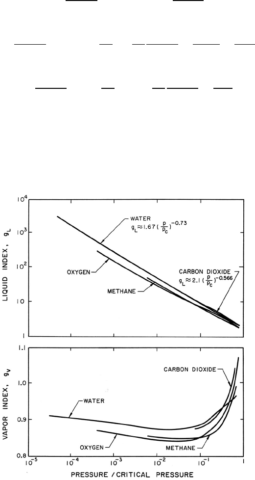
temperature. Some particular values are shown in figure 9.4. Note that g
V
Figure 9.4. Typical values of the liquid index, g
L
, and the vapor index,
g
V
, for various fluids.
230

is close to unity for most fluids except in the neighborhood of the critical
point. On the other hand, g
L
can be a large number that varies considerably
with pressure. To a first approximation, g
L
is given by g
∗
(p
C
/p)
η
where p
C
is
the critical pressure and, as indicated in figure 9.4, g
∗
and η are respectively
1.67 and 0.73 for water. Thus, in summary, f
L
≈ 0, f
V
and g
V
are of order
unity, and g
L
varies significantly with pressure and may be large.
With these magnitudes in mind, we now examine the sensitivity of 1/ρc
2
to the interacting fluid fractions
L
and
V
:
1
ρc
2
=
α
p
[(1 −
V
) f
V
+
V
g
V
]+
(1 − α)
p
L
g
L
(9.23)
Using g
L
= g
∗
(p
c
/p)
η
this is written for future convenience in the form:
1
ρc
2
=
αk
V
p
+
(1 − α)k
L
p
1+η
(9.24)
where k
V
=(1−
V
)f
V
+
V
g
V
and k
L
=
L
g
∗
(p
c
)
η
.Notefirstthatthere-
sult is rather insensitive to
V
since f
V
and g
V
are both of order unity. On
the other hand 1/ρc
2
is sensitive to the interacting liquid fraction
L
though
this sensitivity disappears as α approaches 1, in other words for mist flow.
Thus the choice of
L
is most important at low vapor volume fractions (for
bubbly flows). In such cases, one possible qualitative estimate is that the in-
teracting liquid fraction,
L
, should be of the same order as the gas volume
fraction, α. In section 9.5.2 we will examine the effect of the choice of
L
and
V
on a typical vapor/liquid flow and compare the model with experimental
measurements.
9.4 BAROTROPIC RELATIONS
Conceptually, the expressions for the sonic velocity, equations 9.12, 9.13,
9.14, or 9.23, need only be integrated (after substituting c
2
= dp/dρ)in
order to obtain the barotropic relation, p(ρ), for the mixture. In practice
this is algebraically complicated except for some of the simpler forms for c
2
.
Consider first the case of the two-component mixture in the absence of
mass exchange or surface tension as given by equation 9.13. It will initially
be assumed that the gas volume fraction is not too small so that equation
9.14 can be used; we will return later to the case of small gas volume fraction.
It is also assumed that the liquid or solid density, ρ
L
, is constant and that
p ∝ ρ
k
G
. Furthermore it is convenient, as in gas dynamics, to choose reservoir
conditions, p = p
o
,α= α
o
,ρ
G
= ρ
Go
to establish the integration constants.
231

Then it follows from the integration of equation 9.14 that
ρ = ρ
o
(1 − α)/(1 − α
o
) (9.25)
and that
p
p
o
=
α
o
(1 − α)
(1 − α
o
)α
k
=
α
o
ρ
ρ
o
− (1 − α
o
)ρ
k
(9.26)
where ρ
o
= ρ
L
(1 − α
o
)+ρ
Go
α
o
. It also follows that, written in terms of α,
c
2
=
kp
o
ρ
o
(1 − α)
k−1
α
k+1
α
k
o
(1 − α
o
)
k−1
(9.27)
As will be discussed later, Tangren, Dodge, and Seifert (1949) first made use
of a more limited form of the barotropic relation of equation 9.26 to evaluate
the one-dimensional flow of gas/liquid mixtures in ducts and nozzles.
In the case of very small gas volume fractions, α, it may be necessary
to include the liquid compressibility term, 1 − α/ρ
L
c
2
L
, in equation 9.13.
Exact integration then becomes very complicated. However, it is sufficiently
accurate at small gas volume fractions to approximate the mixture density
ρ by ρ
L
(1 − α), and then integration (assuming ρ
L
c
2
L
= constant) yields
α
(1 − α)
=
α
o
(1 − α
o
)
+
k
(k +1)
p
o
ρ
L
c
2
L
p
o
p
1
k
−
k
(k +1)
p
o
ρ
L
c
2
L
p
p
o
(9.28)
and the sonic velocity can be expressed in terms of p/p
o
alone by using
equation 9.28 and noting that
c
2
=
p
ρ
L
1+
α
(1−α)
2
1
k
α
(1−α)
+
p
ρ
L
c
2
L
(9.29)
Implicit within equation 9.28 is the barotropic relation, p(α), analogous
to equation 9.26. Note that equation 9.28 reduces to equation 9.26 when
p
o
/ρ
L
c
2
L
is set equal to zero. Indeed, it is clear from equation 9.28 that
the liquid compressibility has a negligible effect only if α
o
p
o
/ρ
L
c
2
L
.This
parameter, p
o
/ρ
L
c
2
L
, is usually quite small. For example, for saturated water
at 5 × 10
7
kg/msec
2
(500 psi)thevalueofp
o
/ρ
L
c
2
L
is approximately 0.03.
Nevertheless, there are many practical problems in which one is concerned
with the discharge of a predominantly liquid medium from high pressure
containers, and under these circumstances it can be important to include
the liquid compressibility effects.
Now turning attention to a two-phase rather than two-component homo-
geneous mixture, the particular form of the sonic velocity given in equation
232
9.24 may be integrated to yield the implicit barotropic relation
α
1 − α
=
α
o
(1 − α
o
)
+
k
L
p
−η
o
(k
V
− η)
p
o
p
k
V
−
k
L
p
−η
o
(k
V
− η)
p
o
p
η
(9.30)
in which the approximation ρ ≈ ρ
L
(1 − α) has been used. As before, c
2
may
be expressed in terms of p/p
o
alone by noting that
c
2
=
p
ρ
L
1+
α
1−α
2
k
V
α
(1−α)
+ k
L
p
−η
(9.31)
Finally, we note that close to α = 1 the equations 9.30 and 9.31 may fail
because the approximation ρ ≈ ρ
L
(1 − α) is not sufficiently accurate.
9.5 NOZZLE FLOWS
9.5.1 One dimensional analysis
The barotropic relations of the last section can be used in conjunction with
the steady, one-dimensional continuity and frictionless momentum equa-
tions,
d
ds
(ρAu) = 0 (9.32)
and
u
du
ds
= −
1
ρ
dp
ds
(9.33)
to synthesize homogeneous multiphase flow in ducts and nozzles. The pre-
dicted phenomena are qualitatively similar to those in one-dimensional gas
dynamics. The results for isothermal, two-component flow were first detailed
by Tangren, Dodge, and Seifert (1949); more general results for any poly-
tropic index are given in this section.
Using the barotropic relation given by equation 9.26 and equation 9.25 for
the mixture density, ρ, to eliminate p and ρ from the momentum equation
9.33, one obtains
udu=
kp
o
ρ
o
α
k
o
(1 − α
o
)
k−1
(1 − α)
k−2
α
k+1
dα (9.34)
which upon integration and imposition of the reservoir condition, u
o
=0,
233
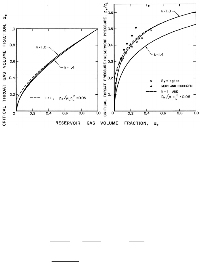
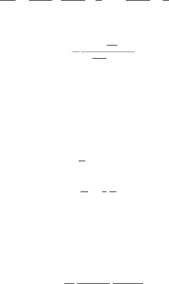
Figure 9.5. Critical or choked flow throat characteristics for the flow of
a two-component gas/liquid mixture through a nozzle. On the left is the
throat gas volume fraction as a function of the reservoir gas volume fraction,
α
o
, for gas polytropic indices of k =1.0and1.4 and an incompressible
liquid (solid lines) and for k = 1 and a compressible liquid with p
o
/ρ
L
c
2
L
=
0.05 (dashed line). On the right are the corresponding ratios of critical
throat pressure to reservoir pressure. Also shown is the experimental data
of Symington (1978) and Muir and Eichhorn (1963).
yields
u
2
=
2kp
o
ρ
o
α
k
o
(1 − α
o
)
k−1
1
k
1 − α
o
α
o
k
−
1 − α
α
k
+
either
1
(k − 1)
1 − α
o
α
o
k−1
−
1 − α
α
k−1
if k =1
or ln
(1 − α
o
)α
α
o
(1 − α)
if k = 1 (9.35)
Given the reservoir conditions p
o
and α
o
as well as the polytropic index k
and the liquid density (assumed constant), this relates the velocity, u,at
any position in the duct to the gas volume fraction, α,atthatlocation.The
pressure, p,density,ρ, and volume fraction, α, are related by equations 9.25
and 9.26. The continuity equation,
A = Constant/ρu = Constant/u(1 − α) (9.36)
234
Figure 9.6. Dimensionless critical mass flow rate, ˙m/A
∗
(p
o
ρ
o
)
1
2
, as a func-
tion of α
o
for choked flow of a gas/liquid flow through a nozzle. Solid
lines are incompressible liquid results for polytropic indices of 1.4 and 1.0.
Dashed line shows effect of liquid compressibility for p
o
/ρ
L
c
2
L
=0.05. The
experimental data () are from Muir and Eichhorn (1963).
completes the system of equations by permitting identification of the loca-
tion where p, ρ, u,andα occur from knowledge of the cross-sectional area,
A.
As in gas dynamics the conditions at a throat play a particular role in
determining both the overall flow and the mass flow rate. This results from
the observation that equations 9.32 and 9.30 may be combined to obtain
1
A
dA
ds
=
1
ρ
dp
ds
1
u
2
−
1
c
2
(9.37)
where c
2
= dp/dρ. Hence at a throat where dA/ds =0: either dp/ds =0,
which is true when the flow is entirely subsonic and unchoked; or u = c,
which is true when the flow is choked. Denoting choked conditions at a
throat by the subscript ∗, it follows by equating the right-hand sides of
equations 9.27 and 9.35 that the gas volume fraction at the throat, α
∗
,must
be given when k =1bythesolutionof
(1 − α
∗
)
k−1
2α
k+1
∗
=
1
k
1 − α
o
α
o
k
−
1 − α
∗
α
∗
k
(9.38)
235

+
1
(k − 1)
1 − α
o
α
o
k−1
−
1 − α
∗
α
∗
k−1
or, in the case of isothermal gas behavior (k = 1), by the solution of
1
2α
2
∗
=
1
α
o
−
1
α
∗
+ ln
(1 − α
o
)α
∗
α
o
(1 − α
∗
)
(9.39)
Thus the throat gas volume fraction, α
∗
, under choked flow conditions is
a function only of the reservoir gas volume fraction, α
o
, and the polytropic
index. Solutions of equations 9.38 and 9.39 for two typical cases, k =1.4and
k =1.0, are shown in figure 9.5. The corresponding ratio of the choked throat
pressure, p
∗
, to the reservoir pressure, p
o
, follows immediately from equation
9.26 given α = α
∗
and is also shown in figure 9.5. Finally, the choked mass
flow rate, ˙m, follows as ρ
∗
A
∗
c
∗
where A
∗
is the cross-sectional area of the
throat and
˙m
A
∗
(p
o
ρ
o
)
1
2
= k
1
2
α
k
2
o
(1 − α
o
)
k+1
2
1 − α
∗
α
∗
k+1
2
(9.40)
This dimensionless choked mass flow rate is exhibited in figure 9.6 for k =1.4
and k =1.
Data from the experiments of Symington (1978) and Muir and Eichhorn
(1963) are included in figures 9.5 and 9.6. Symington’s data on the critical
pressure ratio (figure 9.5) is in good agreement with the isothermal (k =
1) analysis indicating that, at least in his experiments, the heat transfer
between the bubbles and the liquid is large enough to maintain constant
gas temperature in the bubbles. On the other hand, the experiments of
Muir and Eichhorn yielded larger critical pressure ratios and flow rates than
the isothermal theory. However, Muir and Eichhorn measured significant
slip between the bubbles and the liquid (strictly speaking the abscissa for
their data in figures 9.5 and 9.6 should be the upstream volumetric quality
rather than the void fraction), and the discrepancy could be due to the
errors introduced into the present analysis by the neglect of possible relative
motion (see also van Wijngaarden 1972).
Finally, the pressure, volume fraction, and velocity elsewhere in the duct
or nozzle can be related to the throat conditions and the ratio of the area,
A, to the throat area, A
∗
. These relations, which are presented in figures 9.7
and 9.8 for the case k = 1 and various reservoir volume fractions, α
o
,are
most readily obtained in the following manner. Given α
o
and k, p
∗
/p
o
and α
∗
follow from figure 9.5. Then for p/p
o
or p/p
∗
, α and u follow from equations
9.26 and 9.35 and the corresponding A/A
∗
follows by using equation 9.36.
236
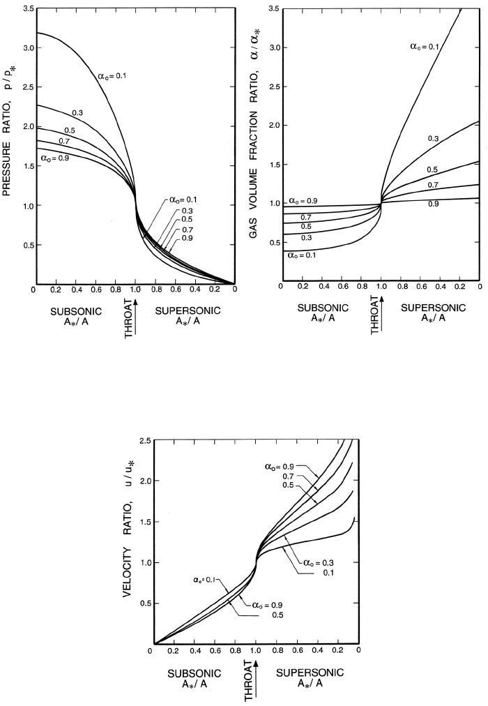
Figure 9.7. Left: Ratio of the pressure, p, to the throat pressure, p
∗
,and
Right: Ratio of the void fraction, α, to the throat void fraction, α
∗
,for
two-component flow in a duct with isothermal gas behavior.
Figure 9.8. Ratio of the velocity, u, to the throat velocity, u
∗
, for two-
component flow in a duct with isothermal gas behavior.
237
The resulting charts, figures 9.7 and 9.8, can then be used in the same way
as the corresponding graphs in gas dynamics.
If the gas volume fraction, α
o
, is sufficiently small so that it is comparable
with p
o
/ρ
L
c
2
L
, then the barotropic equation 9.28 should be used instead
of equation 9.26. In cases like this in which it is sufficient to assume that
ρ ≈ ρ
L
(1 − α), integration of the momentum equation 9.33 is most readily
accomplished by writing it in the form
ρ
L
p
o
u
2
2
=1−
p
p
o
+
1
p/p
o
α
1 − α
d
p
p
o
(9.41)
Then substitution of equation 9.28 for α/(1 − α) leads in the present case
to
u
2
=
2p
o
ρ
L
1 −
p
p
o
+
k
2(k +1)
p
o
ρ
L
c
2
L
p
2
p
2
o
− 1
+
either
k
(k − 1)
α
o
1 − α
o
+
k
(k +1)
p
o
ρ
L
c
2
L
1 −
p
p
o
k−1
k
for k =1
or
α
o
1 − α
o
+
1
2
p
o
ρ
L
c
2
L
ln
p
o
p
for k = 1 (9.42)
The throat pressure, p
∗
(or rather p
∗
/p
o
), is then obtained by equating the
velocity u for p = p
∗
from equation 9.42 to the sonic velocity c at p = p
∗
obtained from equation 9.29. The resulting relation, though algebraically
complicated, is readily solved for the critical pressure ratio, p
∗
/p
o
,andthe
throat gas volume fraction, α
∗
, follows from equation 9.28. Values of p
∗
/p
o
for k =1 and k =1.4 are shown in figure 9.5 for the particular value of
p
o
/ρ
L
c
2
L
of 0.05. Note that the most significant deviations caused by liquid
compressibility occur for gas volume fractions of the order of 0.05 or less.
The corresponding dimensionless critical mass flow rates, ˙m/A
∗
(ρ
o
p
o
)
1
2
,are
also readily calculated from
˙m
A
∗
(ρ
o
p
o
)
1
2
=
(1 − α
∗
)c
∗
[p
o
(1 − α
o
)/ρ
L
]
1
2
(9.43)
and sample results are shown in figure 9.6.
9.5.2 Vapor/liquid nozzle flow
A barotropic relation, equation 9.30, was constructed in section 9.4 for the
case of two-phase flow and, in particular, for vapor/liquid flow. This may be
used to synthesize nozzle flows in a manner similar to the two-component
238