Bhadeshia H.K.D.H., Honeycombe R. Steels: Microstructure and Properties
Подождите немного. Документ загружается.

308 CHAPTER 14 MODELLING OF MICROSTRUCTURE AND PROPERTIES
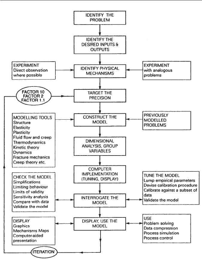
Fig. 14.1 Flow chart illustrating the stages in the construction of a physical model. At each
stage, an iteration back to the earlier stages may be required (after Ashby, Materials Science and
Technology 8, 102–112, 1992).
The first example illustrates how phase transformation theory can be used
in the optimization of a microstructure consisting of a mixture of bainite and
austenite. The problem is first identified to be associated with the occurrence of
large regions of carbon-enriched austenite which are detrimental to toughness.

14.2 EXAMPLE 1: ALLOY DESIGN – HIGH-STRENGTH BAINITIC STEEL 309
The mechanism of transformation is then utilized to reduce the fraction of this
detrimentalphase. Themajor componentof thismodel is thephysical metallurgy
of the transformation. The model is quantitative, in the sense that it requires
the calculation of a phase boundary for a multi-component steel.
The second example helps to understand what is at first sight a strange result,
that the strength of a mixed microstructure of martensite and bainite peaks as a
function of the volume fraction of martensite. It also illustrates how a variety of
approximations can be made in order to formulate a model, both by searching
the published literature for relationships and data, and by adopting a pragmatic
approach.
14.2 EXAMPLE 1: ALLOY DESIGN – HIGH-STRENGTH
BAINITIC STEEL
High-strength bainitic steels have not in practice been as successful as quenched
and tempered martensitic steels, because the coarse cementite particles in bai-
nite are detrimental for toughness (Chapter 6). However, it is now known that
the precipitation of cementite during bainitic transformation can be suppressed.
This is done by alloying the steel with about 1.5 wt% of silicon, which has a very
low solubility in cementite and greatly retards its growth.
An interesting microstructure results when this silicon-alloyed steel is trans-
formed into upper bainite.The carbon that is rejected into the residual austenite,
instead of precipitating as cementite, remains in the austenite and stabilizes it
down to ambient temperature. The resulting microstructure consists of fine
plates of bainitic ferrite separated by carbon-enriched regions of austenite
(Fig. 14.2).
The potential advantages of the mixed microstructure of bainitic ferrite and
austenite can be listed as follows:
1. Cementite is responsible for initiating fracture in high-strength steels. Its
absence is expected to make the microstructure more resistant to cleavage
failure and void formation.
2. The bainitic ferrite is almost free of carbon, which is known to embrittle
ferritic microstructures.
3. The microstructure derives its strength from the ultrafine grain size of the
ferrite plates, which are less than 1 µm in thickness. It is the thickness of these
plates which determines the mean free slip distance, so that the effective
grain size is less than a micrometer. This cannot be achieved by any other
commercially viable process. It should beborne inmind thatgrain refinement
is the only method available for simultaneously improving the strength and
toughness of steels.
4. The ductile films of austenite which are intimately dispersed between the
plates of ferrite have a crack blunting effect. They further add to toughness
by increasing the work of fracture as the austenite is induced to transform
310 CHAPTER 14 MODELLING OF MICROSTRUCTURE AND PROPERTIES
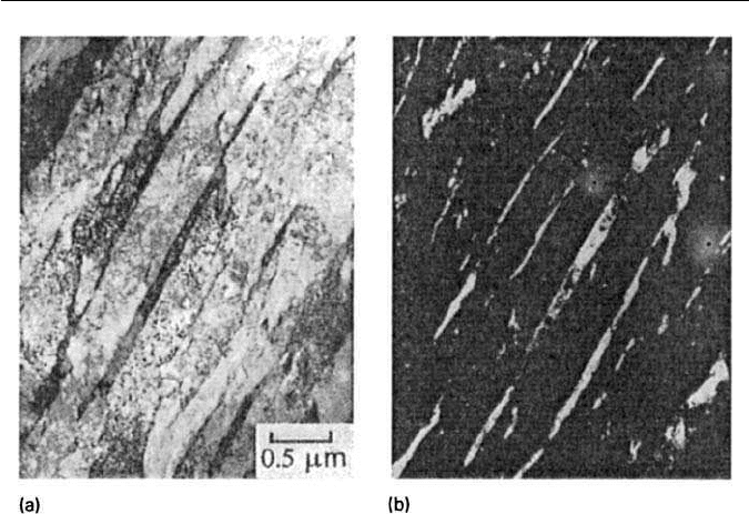
Fig. 14.2 Transmission electron micrograph of a mixture of bainitic ferrite and stable austenite.
(a) Bright field image. (b) Retained austenite dark field image.
to martensite under the influence of the stress field of a propagating crack.
This is the TRIP, or transformation-induced plasticity effect (Chapter 12).
5. The diffusion of hydrogen in austenite is slower than in ferrite. The presence
of austenite can, therefore, improve the stress corrosion resistance of the
microstructure.
6. Steels with the bainitic ferrite and austenite microstructure can be obtained
without the use of any expensive alloying additions. All that is required is
that the silicon concentration should be large enough to suppress cementite.
In spite of these appealing features, the bainitic ferrite/austenite microstruc-
ture does not always give the expected good combination of strength and tough-
ness. This is because the relatively large ‘blocky’ regions of austenite between
the sheaves of bainite (Fig. 14.3) readily transform into high-carbon marten-
site under the influence of stress. This untempered, hard martensite embrittles
the steel.
The blocks of austenite are clearly detrimental to toughness, and anything
that can be done to reduce their fraction,or increase their stability to martensitic
transformation, would be beneficial. Both of these effects are controlled by the
T
′
0
curve of the phase diagram (Chapters 5 and 6). This curve determines the
composition of the austenite at the point where the reaction to bainite stops. By
displacing the curve to larger carbon concentrations, both the fraction of bainite
that can form, and the carbon concentration of the residual austenite can be
14.2 EXAMPLE 1: ALLOY DESIGN – HIGH-STRENGTH BAINITIC STEEL 311
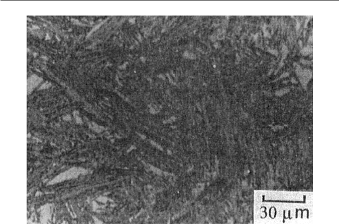
Fig. 14.3 Optical micrograph of upper bainite in an Fe–0.43C–3Mn–2.02Si wt% showing the
blocks of retained austenite between sheaves of bainite.
increased. Modifications to the T
′
0
curve can be achieved by altering the alloy
composition. It is therefore necessary to calculate the effect of substitutional
solutes on the T
′
0
curve.
14.2.1 Calculation of the T
′
0
curve
At the T
′
0
temperature, the free energies of austenite and ferrite of the same
chemical composition are identical (Chapter 6). A calculation of the T
′
0
tem-
perature for binary alloys was discussed in Chapter 5. A simplified method is
presented here for multi-component steels. At the T
′
0
temperature point, the
change in free energy as austenite transforms to ferrite is zero:
G
γα
= 0. (14.1)
Zener argued that the free energy difference can be factorized into two
components, the magnetic (G
γα
M
) and non-magnetic (G
γα
NM
) terms:
G
γα
= G
γα
M
+ G
γα
NM
. (14.2)
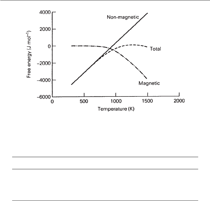
The non-magnetic component varies approximately linearly with temperature
(Fig. 14.4) but the magnetic component varies non-linearly, becoming nearly
zero at low temperatures. However, over a restricted temperature range (in
which bainite usually forms), both functions can be represented approximately
as in Table 14.1.
312 CHAPTER 14 MODELLING OF MICROSTRUCTURE AND PROPERTIES
Fig. 14.4 Zener’s factorization of the free energy difference between the austenite and ferrite
phases into magnetic and non-magnetic components.
Table 14.1 Approximate representations of the free energy components for
the γ →α transformation in pure iron
Function abTemperature range
G
γα
NM
=a +bT J mol
−1
−6660 7 900 > T > 300 K
G
γα
NM
=a +bT J mol
−1
650 −1 900 > T > 620 K
G
γα
M
=a +bT J mol
−1
00 T < 620 K
The Zener factorization of the free energy into magnetic and non-magnetic
components helps to account for the effects of alloying elements, via a
modification of the temperature at which the free energy is evaluated:
G
γα
{T}=G
γα
M
{T − xT
M
}+G
γα
NM
{T − xT
NM
}. (14.3)
T
M
and T
NM
are temperature changes due to a unit concentration (x)of
substitutional solute (Table 14.2). The T
0
temperature is therefore calculated
by setting G
γα
to zero:
G
γα
M
{T
0
− xT
M
}+G
γα
NM
{T
0
− xT
NM
}=0. (14.4)
On substituting the expressions listed in Table 14.1, this becomes:
a
NM
+ b
NM
T
Fe
0
+ a
M
+ b
M
T
Fe
0
= 0 for pure iron,
and
a
NM
+b
NM
(T
FeX
0
−xT
NM
) +a
M
+b
M
(T
FeX
0
−xT
M
) = 0 for an iron alloy.

14.2 EXAMPLE 1: ALLOY DESIGN – HIGH-STRENGTH BAINITIC STEEL 313
It follows that the change in the T
0
temperature caused by the addition of a
substitutional element is given by the difference between these two equations:
T
0
=
x(b
NM
T
NM
+ b
M
T
M
)
b
NM
+ b
M
. (14.5)
The effect of several alloying elements can be approximated by assuming
additivity:
T
0
=
i
x
i
(b
NM
T
NM
i
+ b
M
T
M
i
)
b
NM
+ b
M
. (14.6)
To calculate the shift in the T
′
0
temperature, we simply set G
γα
to the value
of the stored energy (say 400 J mol
−1
for bainite) instead of to zero. The actual
T
′
0
curve for an alloy, rather than just the shift T
′
0
relative to pure iron, can be
estimated by noting for an Fe–C alloy, allowing for 400 J mol
−1
of stored energy:
T
′
0
(K) ≃ 970 − 80x
c
, (14.7)
where x
c
is the at % of carbon.
We can now proceed to apply this methodology to the design of a tough
bainitic ferrite/austenite microstructure.
14.2.2 The improvement in toughness
An apparently ideal microstructure consisting of bainitic ferrite and ductile
austenite in a Fe–3Mn–2.02Si–0.43C wt% exhibits poor toughness because of
the presence of blocky unstable austenite (Fig. 14.5a). It is necessary to increase
the amount of bainitic ferrite in the microstructure and to increase the stability
of the austenite. Both of these aims can be achieved by changing the substitu-
tional solute concentration such that the T
′
0
curve is shifted to higher carbon
concentrations (i.e. T
′
0
is raised at any given carbon concentration).
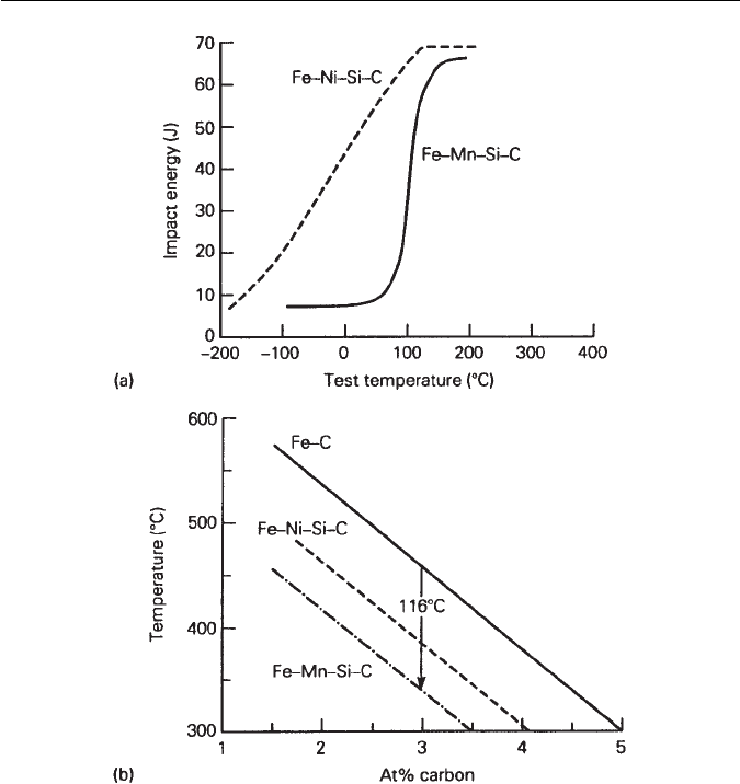
Using Equation (14.6), we see that for the Fe–3Mn–2.02Si–0.43C wt%
(2.97 Mn, 3.87Si at%) alloy:
T
0
=
Mn
2.97[7 × (−39.5) + (−1) × (−37.5)]
7 − 1
+
Si
3.87[7 × (0) + (−1) × (−3)]
7 − 1
=116,
thefirst term onthe right-hand sidebeing theeffect of manganeseandthe second
the effect of silicon. Hence,for this alloy Equation (14.7) can be modified to give:
T
′
0
(K) ≃ 970 − 80x
c
− 116. (14.8)
314 CHAPTER 14 MODELLING OF MICROSTRUCTURE AND PROPERTIES
Fig. 14.5 (a) Experimentally determined impact transition curves showing how the toughness
improves as the amount of blocky austenite is reduced. (b) CalculatedT
′
0
curves for the Fe–C,
Fe–Mn–Si–C and Fe–Ni–Si–C steels.
Manganese is seen to have a large effect in depressing the T
′
0
temperature. An
examination of Table 14.2 shows that one possibility is to replace all of the man-
ganese with nickel. Thus, for a Fe–4Ni–2Si–0.4C wt% (3.69Ni, 3.85Si at%) alloy,
a similar calculation shows that T
0
≃72 so that:
T
′
0
(K) ≃ 970 − 80x
c
− 72. (14.9)
The remarkable improvement in toughness achieved by doing this, without
any sacrifice of strength, is illustrated in Fig. 14.5, along with the T
′
0
curves
as calculated above.

14.3 EXAMPLE 2: MECHANICAL PROPERTIES OF MIXED MICROSTRUCTURES 315
Table 14.2 Values of T
M
and T
NM
for a variety of substitutional
solutes (Aaronson et al.,Transitions of the Metallurgical Society of AIME
236, 753–780, 1966)
Alloying element T
M
/K per at % T
NM
/K per at %
Si −30
Mn −37.5 −39.5
Ni −6 −18
Mo −26 −17
Cr −19 −18
V −44 −32
Co 19.5 16
Al 8 15
Cu 4.5 −11.5
14.2.3 The precision of the model
The model discussed above has helped in achieving the desired goal of improved
toughness, even though the method used is in fact crude. The T
′
0
curves are not
really linear functionsof carbon,and the interactionsof carbonwith the substitu-
tional solutes are not accounted for. Rigorous methods are available and could
be usedwhen considering ahigher degree of optimization of steel chemistry.The
model also does not incorporate kinetics. This could be a major disadvantage
because in commercial practice, microstructures are usually generated using
complex non-isothermal heat treatments.
Referring to Fig. 14.1, it is obvious that the exploitation of these concepts
would require several iterations to improve precision, and to adapt the model
for complex industrial processing. These examples illustrate the essentials of
the modelling technique. Models can be constructed in stages, with significant
advances being made at each stage, even though the ultimate problem may not
be solved completely. These successes at each stage of the model can be used to
justify further development until a point of diminishing returns is reached.
14.3 EXAMPLE 2: MECHANICAL PROPERTIES OF MIXED
MICROSTRUCTURES
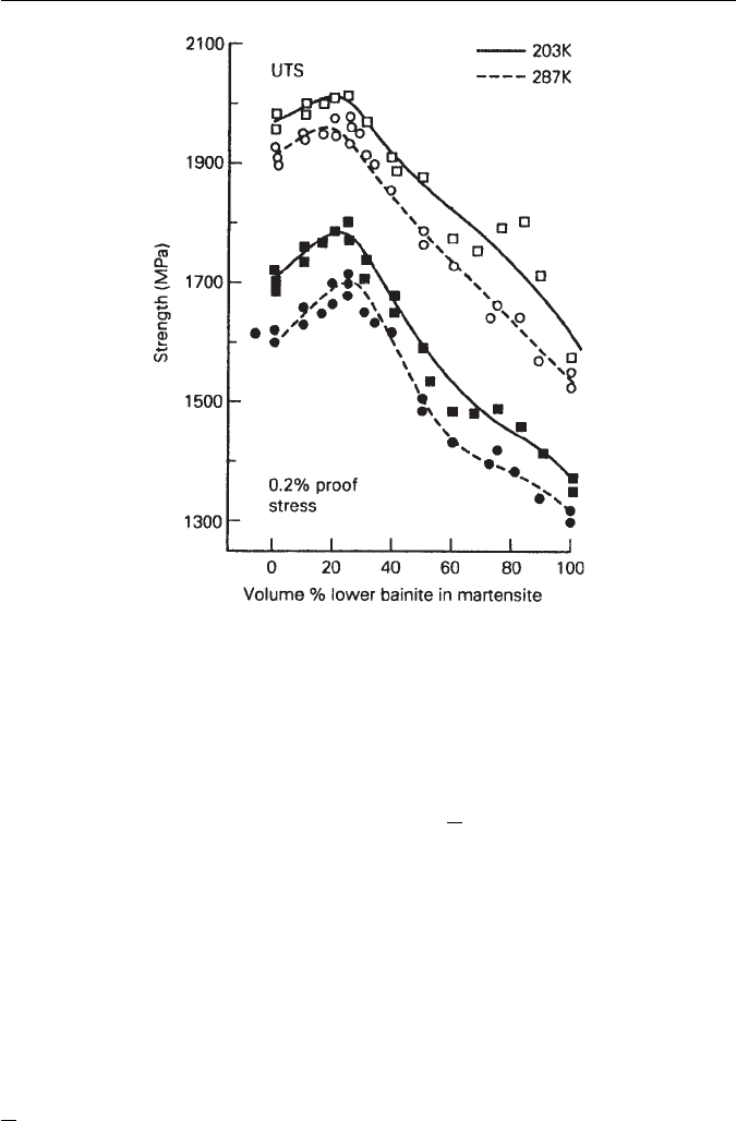
A peculiar feature of mixed microstructures of bainite and tempered martensite,
is that the strength is found to go through a peak as the volume fraction of
martensite decreases (Fig. 14.6). This is against intuition in that martensite is
usually considered to be the strongest microstructure in steels, in which case the
strength should decrease continuously as the fraction of martensite is reduced.
However,quantitative modelling,by helping to reveal the mechanisms involved,
can explain this anomalous behaviour.
316 CHAPTER 14 MODELLING OF MICROSTRUCTURE AND PROPERTIES
Fig. 14.6 Strength of bainite and tempered martensite as a function of the volume fraction
of bainite (Tomita and Okabayashi, Metallurgical Transations A 14A, 485, 1983).
14.3.1 Calculation of the strength of individual phases
It is reasonable to assume that the strength of martensite and bainite can be
factorized into a number of intrinsic components:
σ = σ
Fe
+
i
x
i
σ
SS
i
+ σ
C
+ K
L
(
L)
−1
+ K
D
ρ
0.5
D
, (14.10)
where x
i
is the concentration of a substitutional solute which is represented here
by a subscript i. The other terms in this equation can be listed as follows:
K
L
=coefficient for strengthening due to lath size, 115 MN m
−1
K
D
=coefficient for strengthening due to dislocations, 7.34 ×10
−6
MN m
−1
σ
Fe
=strength of pure, annealed iron, 219 MN m
−2
at 300 K
σ
SSi
=substitutional solute (i) strengthening
σ
c
=solid solution strengthening due to carbon
ρ
D
=dislocation density, typically 10
16
m
−2
L =measure of the ferrite plate size, typically 0.2 µm.
The individual strengthening contributions are discussed below.

14.3 EXAMPLE 2: MECHANICAL PROPERTIES OF MIXED MICROSTRUCTURES 317
Table 14.3 Strength (MN m
−2
) of pure iron as a function of temperature
and solid solution strengthening terms for ferrite, for one wt% of solute. The
data are for a strain rate of 0.0025 s
−1
200
◦
C 100
◦
C Room temperature −40
◦
C −60
◦
C
(23
◦
C)
Fe 215 215 219 355 534
Si 78 95 105 70 −44
Mn 37 41 45 8 −57
Ni 19 23 37 −2 −41
Mo – – 18 – –
Cr 7.8 5.9 5.8 7.4 15.5
V – – 4.5 – –
Co 1.0 1.8 4.9 9.1 5.8
14.3.2 Iron and substitutional solutes
Pure body-centred cubic iron in a fully annealed condition makes an intrinsic
contribution σ
Fe
to the overall strength. Substitutional solutes do not parti-
tion during the displacive growth of either martensite or bainite, so that their
concentrations are fixed by the composition of steel as a whole. Solid solution
strengthening contributions, σ
SSi
can be estimated as a function of temperature
and strain rate from published data. Table 14.3 shows that whereas the strength
of pure iron increases as the temperature is reduced, strengthening due to sub-
stitutional solutes often goes through a maximum as a function of temperature.
Indeed, there is some solution softening at low temperatures because the pres-
ence of aforeign atom locallyassists a dislocationto overcome thePeierls barrier
at low temperatures.
14.3.3 Carbon
Bainitic ferrite has only a small amount of carbon dissolved in interstitial solu-
tion, assumed to be less than 0.02 wt%. Martensite, on the other hand, can have
concentrations well in excess of
x (the average concentration of the alloy), since
the prior formation of bainite enriches the residual austenite according to the
following relationship derived from a balance of mass. The total carbon concen-
tration in the alloy (
x) is the sum of the concentrations in the austenite (x
γ
) and
bainitic ferrite (x
b
):
x = x
γ
V
γ
+ x
b
V
b
, (14.11)
where V
γ
and V
b
are the volume fractions of austenite and bainitic ferrite,
respectively. It follows that:
x
γ
=
x −V
b
x
b
1 − V
b
, (14.12)