Bennemann K.H., Ketterson J.B. Superconductivity: Volume 1: Conventional and Unconventional Superconductors; Volume 2: Novel Superconductors
Подождите немного. Документ загружается.


22 A Spin Fluctuation Model for d-Wave Superconductivity 1391
−2
(T =0)+B
4
T log T where B = O(1), and
4
is the effective four boson interaction that is made
out of fermions [75,76,124]. The T log T factor is the
universal contribution from the bosonic loop, con-
fined to momentanear Q.The four-bosoninteraction
has two contributions: one comes from low-energy
fermions and is universal; the other comes from
high-energy fermions and depends on the fermionic
bandwidth W. One can show [124] that the temper-
ature correction to involves only the high-energy
part of the interaction (this is what we labeled as
4
). The magnitude of
4
can be easily estimated
to be ¯g
2
/W
3
. Accordingly, the temperature correc-
tion to scales as
T
¯g
(¯g/W)
3
.Aswehaveremarked,
the theory is universal as long as ¯g W.Inthis
limit, the temperature dependence of is obviously
small and can be neglected. This is what we will
do. Notice however that in the opposite limit, when
¯g W, the full four-boson interaction differs from
the lowest order term in ¯g and might be estimated
within an RPA-type summation. Estimates show that
in this limit, the full
4
is fully determined within
the low-energy sector and scales as O(1/J)where
J ∼ W
2
/¯g is the magnetic exchange integral. This in
turn yields a much stronger temperature dependence
of :
−2
(T)−
−2
(T =0)∼ (T/J)logT.Thisresultis
similar to that obtained using a nonlinear -model
approach to near antiferromagnetism [127,172,173].
The agreement becomes obvious in the limit of a
large spin–fermion interaction (which, we recall, is
the Hubbard U if we derive the spin–fermion model
within the RPA); double occupancy is energetically
unfavorable and the spin susceptibility obeys the
constraint
d
2
qd!(q, i!) ∝ 1−x.Thisisequiv-
alent to imposing a constraint on the length of the
spin field in the nonlinear -model [127,172,173].
22.6.2 The Normal State
In this section we compare the experimental and the-
oreticalformsof the fermionic spectral functionand
optical conductivity in the normal state. No free pa-
rameters remain, since those which are needed to
specify the model completely have been taken from
NMR and ARPES experiments. The discussion will
follow [49].
The Spectral Function
The quasiparticle spectral function at various mo-
menta is measured in angle resolved photoemission
experiments. In a sudden approximation (an elec-
tron, hit by light, leaves the crystal without further
interactionswith other electrons and without paying
attention to selection rules for the optical transition
toits finalstate),the photoemission intensityis given
by I
k
(!)=A
k
(!)n
F
(!)wheren
F
is the Fermi func-
tion and A
k
(§)=(1/) |ImG(k, §)| is the spectral
function.
We first use our form of the fermionic self-energy
to fit MDC data which measure the width of the
photoemission peak as a function of k at a given
frequency. In Fig. 22.27 we compare the theoreti-
cal results for k = £
(k, §)/v
F
with the measured
k versus frequency at T ∼ 100K [137] and versus
temperature at § → 0 [166]. We used =1.7and
!
sf
=20meV.Theslopeofk is chiefly controlled
by .We obtain rather good agreement with the data,
both for the frequency and temperature dependence
of the self-energy. On the other hand,the magnitude
of our£
issmallerthanthat foundintheexperimen-
tal data [174].To account for the values of k,wehad
to add a constant of about70meV to£
.The originof
this constant is unclear and explaining it is presently
a challenge to the theory.It may be the effect of elastic
scattering by impurities [175], but the large value of
this constant implies that it is more likely the contri-
bution from scattering channels that we ignored. It
is essential, however, that the functional dependence
of £
(§, T) can be captured in the spin-fluctuation
approach.
In Fig. 22.28 we present the results for the half
width at half maximum of the EDC (energy distri-
bution curve) which measures fermionic I
k
(§)=
A
k
(§)n
F
(§) as a function of frequency at a given
k. For a Lorentzian line-shape, the EDC hwhm is
given by £
(§)/(1 + £
(§)/§). The data are taken
at T = 115K [137]. We see that the theoretical slope
agrees reasonably well with the experimental one.
The visiblediscrepancy is mostlikely associated with
the fact that the experimental line-shape is not a per-
fect Lorentzian.
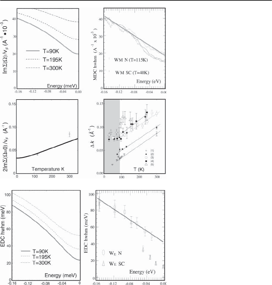
1392 A.V. Chubukov, D. Pines, and J. Schmalian
Fig. 22.27. A comparison between the the-
oretical results of the spin–fermion model
and the photoemission MDC data. For the
Lorentzian line-shape of the MDC signal,
observed in experiments, the MDC hwhm
equals to £
/v
F
. Upper panel:theresults
for the MDC hwhm vs frequency at a given
T. The experimental results are taken from
[137]. Lower panel:theMDCfwhmvstem-
perature at § = 0. The experimental results
(right figure and the points on the left figure)
are taken from [166]. The figure is taken
from [49]
Fig. 22.28. A comparison of the theoretical
result for £
(§)/(1 + £
(§)/§)withtheex-
perimental hwhm of the EDC dispersion
from [137]. The figure is taken from [49]
The Optical Conductivity
In Fig. 22.29 we compare the theoretical results for
the conductivity[161]with the experimental data for
1
and
2
at different temperatures [176]. The theo-
retical results are obtained using the same =1.7
and !
sf
= 20meV as in the fit to the photoe-
mission data along zone diagonals. Changing af-
fects the ratio
2
/
1
at high frequencies, but does
not change the functional forms of the conductivi-
ties [161]. The theoretical value of the plasma fre-
quency was adjusted [161] to match the d.c. conduc-
tivity [144,176,177].We see that theoretical calcula-
tions of
1
(!)and
2
(!) capture the essential fea-
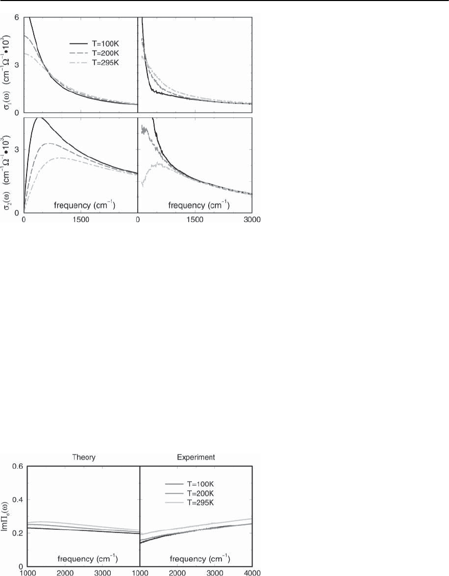
22 A Spin Fluctuation Model for d-Wave Superconductivity 1393
Fig. 22.29. The theoretical and experimental re-
sults for the real and imaginary parts of optical
conductivity. The data are from [176]. The fig-
ure is taken from [49]
tures of the measured forms of the conductivities.In
particular, the curves of
1
at different temperatures
cross such that at the lowest frequencies, the con-
ductivity decreases with T while at larger frequen-
cies it increases with T, a behavior seen in [177,179].
The imaginary part of conductivity decreases with
T at any frequency, and the peak in
2
(!) increases
in magnitude and shifts to lower T with decreasing
T [176–178].At frequencies above 1500cm
−1
both
1
and
2
depend weakly on T and are comparable in
amplitude.
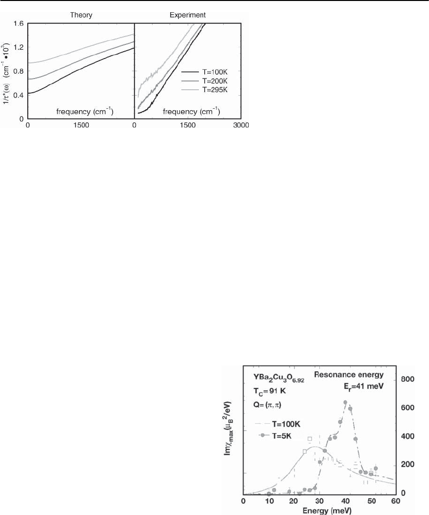
To make the comparison more quantitative, in
Fig. 22.30 we present experimental and theoretical
results for the imaginary part of the full particle–
hole polarization bubble ¢
(!)=4
1
!/!
2
pl
.The-
oretically, at T =0,¢
(!) saturates at a value of
about 0.2 independently of and remains almost in-
dependent of frequency over a very wide frequency
range [161]. The experimental data also clearly show
a near saturation of ¢
at a value close to 0.2.
The agreement between theory and experiment is,
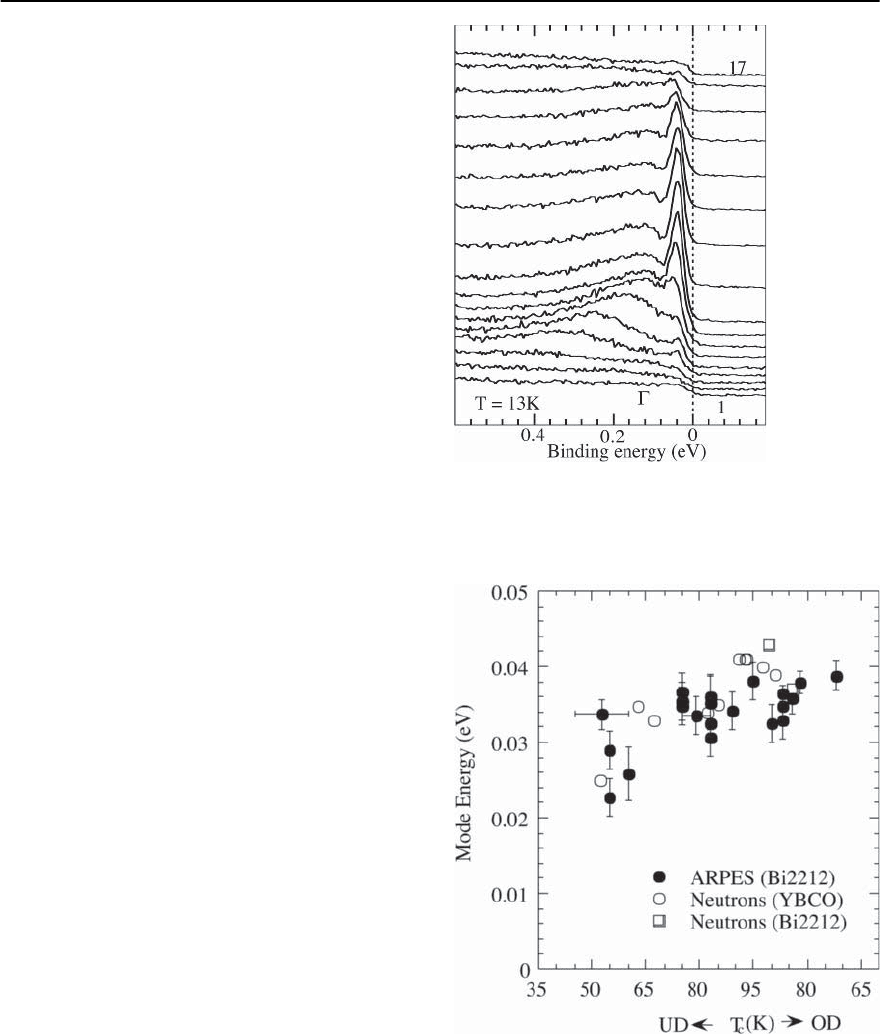
however, not a perfect one. In Fig. 22.31 we show the-
oretical and experimental results for 1/
∗
= !
1
/
2
.
Theadvantage of comparing 1/
∗
is thatthis quantity
does not depend on the unknown plasma frequency.
We see that while both experimental and theoreti-
cal curves are linear in frequency, the slopes are off
roughlybyafactorof3.Thisdiscrepancyispossibly
related to the fact that in the spin–fermion model,
¢
(!)athighenoughfrequenciesisroughly3times
Fig. 22.30. The theoretical and experimental re-
sults for ¢
(!)=4
1
!/!
2
pl
(from [49]). The
data are from [176]
1394 A.V. Chubukov, D. Pines, and J. Schmalian
Fig. 22.31. The theoretical and experimental re-
sults for 1/
∗
= ! Re /Im (from [49]). The
data are from [176]
larger than ¢
(!) [161], and hence
2
/
1
∼ 3,
whereas experimentally
1
and
2
are comparable
in magnitude at high frequencies. The discrepancy
in 1/
∗
indicates that either the averaging over the
Fermi surface, vertex corrections inside a particle–
hole bubble, or RPA-type corrections to the conduc-
tivity [180] play some role. Still, Figs.22.29 and 22.30
indicate that the general trends of the behavior of the
conductivities near optimal doping are reasonably
well captured within the spin-fluctuation approach.
22.6.3 The Superconducting State
In this section, we apply our results from Sect. 22.5
to cuprates and examine to what extent the “fin-
gerprints” of spin-fluctuation pairing have been de-
tected in experiments on optimally doped high-T
c
materials.
The Spin Susceptibility
The major prediction of the spin fermion model for
the spin susceptibility in the superconducting state
is the emergence of the resonance peak in
(Q, !)
at ! =
s
if
s
< 2.Themagnitude
s
is fully de-
termined within the theory and is chiefly set by the
magnitude of the superconducting gap as well as the
energy scale of magnetic fluctuations in the normal
state, !
sf
. For small doping concentration
s
∝
−1
must decrease as one approaches the antiferromag-
netic state.Theresonancemodeis confinedto asmall
region in momentum space (where it is of high inten-
sity). For momenta away from Qandits close vicinity,
magnetic excitations couple to gapless, nodal quasi-
particles and become overdamped, eliminating the
resonance mode.
In Fig. 22.32 we show representative experimen-
tal data for
(Q, !) showing the resonance peak
at ! ≈ 41 meV for optimally doped YBa
2
Cu
3
O
6.9
[181]. As noted earlier, the position of the peak is
consistent with the prediction of the spin fermion
model. Similar behavior is found in Bi
2
Sr
2
CaCu
2
O
8
[146]; here the peak is at 43 meV. With under-
doping, the measured resonance energy goes down
[138, 139]. In strongly underdoped YBa
2
Cu
3
O
6.6
,it
is approximately 25 meV [138]. The existence of
the peak and the downturn with underdoping agree
with the predictions of the spin-fluctuation theory.
Further, the measured amplitude of
(Q, !)de-
creases above the peak, but increases again for 60–
80 meV [139,181].This might indeed be a 2 effect,
which appears naturally within the model.
Fig. 22.32. Inelastic neutron scattering intensity for
momentum Q =
(
,
)
as function of frequency for
YBa
2
Cu
3
O
6.92
. Data from [181]
22 A Spin Fluctuation Model for d-Wave Superconductivity 1395
The full analysis of the resonance peak requires
more care as (i) the peak is only observed in two-
layer materials, and only in the odd channel, (ii) the
momentum dispersion of the peak is more complex
than that for magnons [165], (iii) the peak broad-
ens with underdoping [138,139], and (iv) in under-
doped materials, the peak emerges at the onset of
the pseudogap and only sharpens up at T
c
[139,181].
All these features, already present on the level of a
weak coupling approach [128–130], have been ex-
plained within the spin–fermion model [89,134].The
broadening of the peak was recently studied in detail
in[132].Theexplanationof theseeffects,however,re-
quires careful analysis of the details of the electronic
structure and is beyond the scope of this chapter.
The Spectral Function
The predictions of our approach are a peak-dip
structure of the spectral function, with a weakly dis-
persing peak at ! ≈ and a peak–dip distance
≈
s
. On the other hand we expect a broad incoher-
ent peak which disperses like
2
k
/ ¯!. In Fig. 22.33 we
presentARPES data for near optimally dopedBi2212
with T
c
= 87K for momenta near a hot spot [140].
The intensity displays the predicted peak/dip/hump
structure.A sharp peak is located at ∼ 40meV, and
the dip is at 80meV such that the peak–dip distance
is 42meV [140]. In the spin-fluctuation theory, the
peak-dip distance is the energy of the INS resonance
peak frequency [123, 128]. The neutron scattering
data on Bi2212 with nearly the same T
c
=91K
yield [146]
s
= 43 meV,in excellent agreement with
this prediction.
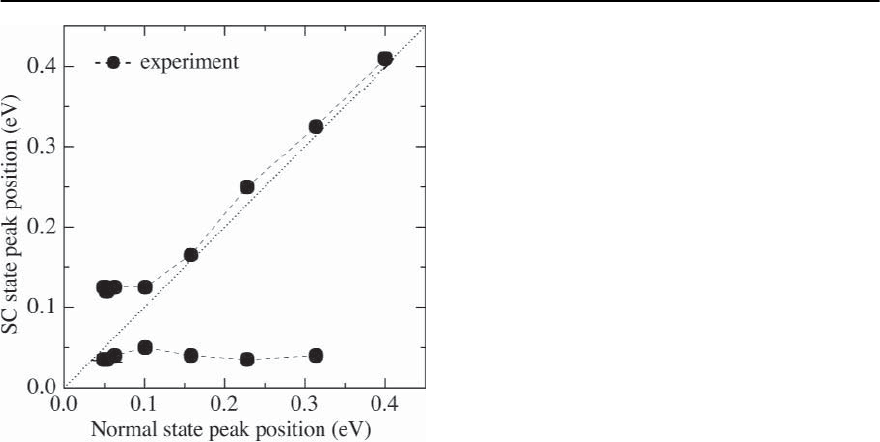
Furthermore,with underdoping,the peak-dip en-
ergy difference decreases and, within error bars, re-
mains equal to
s
.Thisbehaviorisillustratedin
Fig. 22.34.
In Fig. 22.35 we present experimental results for
the variation of the peak and hump positions with
the deviation from the Fermi surface. These show
that the hump disperses with k − k
F
and eventually
recovers the position of the broad maximum in the
normal state. At the same time, the peak shows little
dispersion,and does not move further in energy than
+
s
. Instead, the amplitude of the peak dies off as
Fig. 22.33. ARPES spectrum for near optimally doped
Bi2212 for momentaclose to the hot spots.Data from [140]
Fig. 22.34. The experimental peak–dip distance at various
doping concentrations compared with
s
extracted from
neutron measurements. Data from [30]. The theoretical re-
sult is presented in Fig. 22.18
1396 A.V. Chubukov, D. Pines, and J. Schmalian
Fig. 22.35. The dependence of the experimental peak (flat
curve) and hump (dispersing curve) positions on the de-
viation from the Fermi surface. The hump disperses with
k − k
F
(dotted line) and eventually recovers the position
of the broad maximum in the normal state, while the peak
position changes little with the deviation from k
F
.Data
from [140]. The theoretical result is presented in Fig.22.18
k moves away from k
F
.Thisbehaviorisagainfully
consistent with the theoretical predictions [49,156].
We regardthe presence of the dip at +
s
,andthe
absence of the dispersion of the quasiparticle peak as
two major “fingerprints” of strong spin-fluctuation
scattering in the spectral density of cuprate super-
conductors.
The Density of States
The fermionic DOS N(!)isproportionalto
the dynamical conductance dI/dV through a
superconductor-insulator-normal metal (SIN) mea-
sured at ! = eV,whereV is theappliedvoltage [152].
The key prediction of our approach is the occurrence
of a dip in the DOS at an energy ≈
s
away from the
peak at ! = .ThedropintheDOSat§
t
= +
s
can be understood in terms of SIN conductance as
follows: when the applied voltage, V,equals§
t
/e an
electron that tunnels from a normal metal can emit
a spin excitation and fall to the bottom of the band,
losing its group velocity.Thisloss leads to a sharp re-
duction of the current and produces a drop in dI/dV.
This process is shown schematically in Fig. 22.22.
SIN tunneling experiments have been performed
on YBCO and Bi2212 materials [142]. We reproduce
these data in Fig. 22.36. Similar results have been
recently obtained by Davis et al. [182]. At low and
moderate frequencies, the SIN conductance displays
a behavior which is generally expected in a d-wave
superconductor, i.e. it is linear in voltage for small
voltages, and has a peak at eV = where is the
maximum value of the d-wave gap [142,182] The
value of extracted from tunneling agrees well with
the maximum value of the gap extracted fromARPES
measurements [136,137].At frequencies larger than
, the measured SIN conductance clearly displays
an extra dip-hump feature which become visible at
around optimal doping,andgrows inamplitude with
underdoping [142].At optimal doping, the distance
between the peak at andthedipisaround40meV.
This is consistent with
s
extracted from neutron
measurements.
SIS Tunneling
The major prediction of the spin–fermion model for
the SIS tunneling conductance, S(!), is the emer-
gence of a singularity at ! =2 +
s
.Asmen-
tioned above, this singularity is likely softened due
to thermal excitations or non-magnetic scattering
processes and transforms into a dip slightly below
2+
s
,and a humpata frequency larger than 2+
s
.
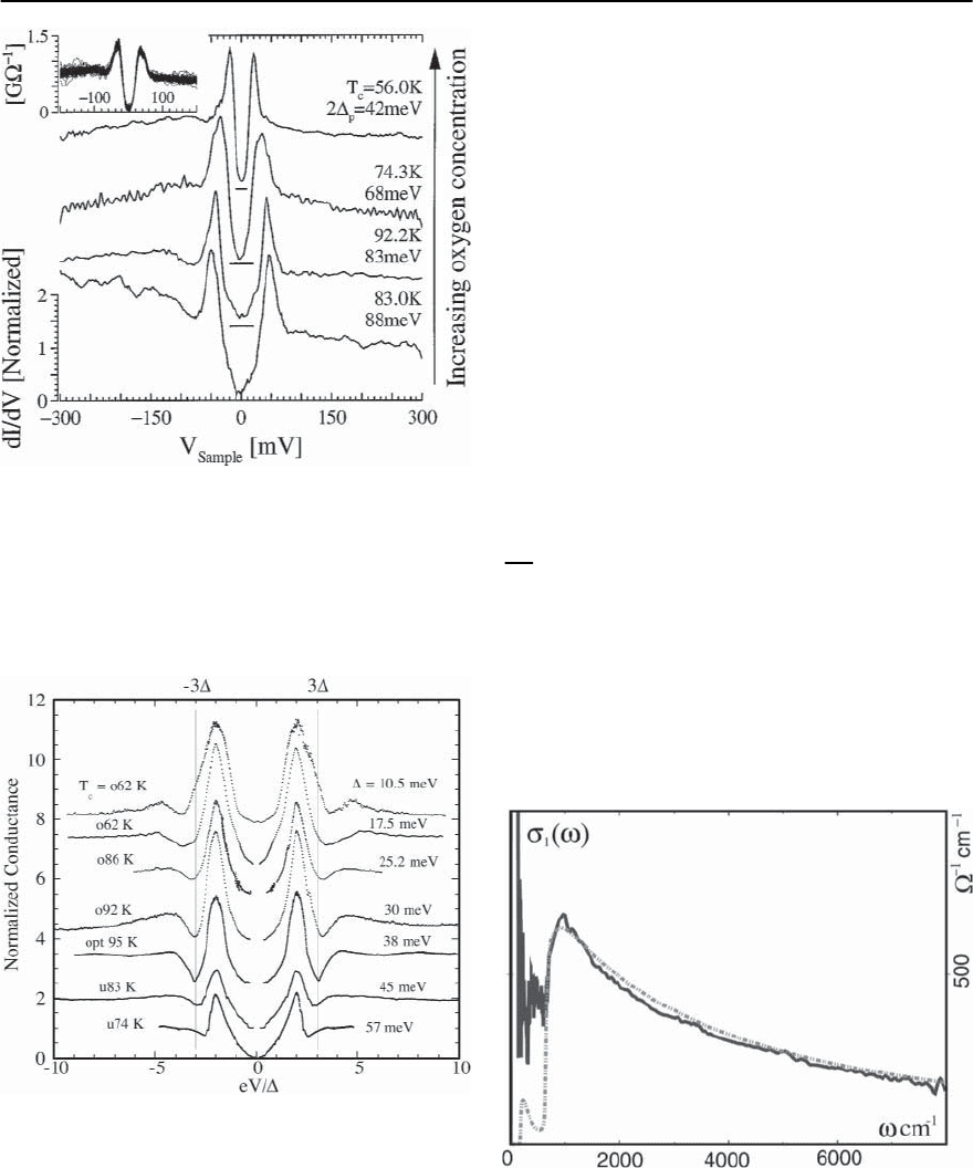
Recently, Zasadzinski et al. obtained both new data
and carefully examined their previous SIS tunneling
data for a set of Bi2212 materials ranging from over-
doped to underdoped [143]. Their data, presented
in Fig. 22.37 show that in addition to the peak at
2, the SIS conductance displays the dip and the
hump at larger frequencies. The distance between
the peak and the dip (which approximately equals
s
in the spinfluctuationmodel [123,133])is close to2
in overdoped Bi2212 materials, but goes down with
underdoping. Near optimal doping, this distance is
around 40meV. For an underdoped, T
c
= 74K, ma-
terial, the peak-dip distance is reduced to about
30meV. These results are in qualitative and quanti-
22 A Spin Fluctuation Model for d-Wave Superconductivity 1397
Fig. 22.36. The experimental result for the differential con-
ductance through theSIN tunneling junction.Thisconduc-
tance is proportional to the quasiparticle DOS.The data are
for Bi2212 and are taken from Ref. [142]. The theoretical
result is presented in Fig. 22.20(d)
Fig. 22.37. SIS tunneling conductance normalized by
for Bi2212 materials ranging from overdoped (top curves)
to underdoped (bottom curves) from [143]. The peak dip
distance increases for increasing doping and saturates at
around 3 as expected in our theory. The corresponding
theoretical result is presented in Fig. 22.21
tative agreement with ARPES and neutron scattering
data, as well as with the theoretical estimates. The
most important aspect is that with underdoping, the
experimentally measuredpeak-dip distance progres-
sively shifts down from 2. This downturn deviation
from 2 is a key featureofthespin-fluctuation mech-
anism. We regard the experimental verification of
this feature in the SIS tunneling data as an additional
strong argument in favor of the magnetic scenario
for superconductivity.
Optical and Raman Response
Theoretical considerations show that optical mea-
surements are much better suited than Raman mea-
surements to search for the “fingerprints” of a mag-
netic scenario [133]. For the optical conductivity we
predict a singular behavior at energies 2 +
s
,4,
2 +2
s
, which can be amplified if one considers
the second derivative of conductivity via W(!)=
d
2
d
2
!
(!Re
−1
(!)). Evidence for strong coupling ef-
fects in the optical conductivity in superconducting
cuprates has been reported in [144,145,183,184].
We first discuss the form of
1
(!).In Fig.22.38 we
compare the theoretical result for
1
(!) [133, 161]
with the experimental data by Puchkov et al. [144]
for optimally doped YBa
2
Cu
3
O
6+ı
in the supercon-
ducting state. The parameters are the same as in
the normal state fits.As the theoretical formula does
Fig. 22.38. A comparison between theoretical and exper-
imental results for the optical conductivity (from [161]).
The experimental data are from [144]
1398 A.V. Chubukov, D. Pines, and J. Schmalian
not include the contributions from the nodes, the
comparison is meaningful only for ! > 2.Wesee
that the frequency dependence of the conductivity at
high frequencies agrees well with the data. The mea-
sured conductivity drops at about 100meV in rough
agreement with 2 +
s
which for ≈ 30 meV and
s
≈ 40 meV is also around 100 meV. The good
agreement between theory and experiment is also
supportive of our argument that the momentum de-
pendence of the fermionic dynamics becomes irrel-
evant at high frequencies, and fermions from all over
the Fermi surface behave as if they were at hot spots.
We next considerthe singularities in thefrequency
dependence of the conductivity in more detail and
compare the theoretical and experimental results for
W(!)=
d
2
d
2
!
(!Re
−1
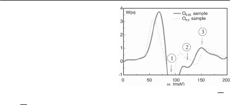
(!)). The theoretical result for
W(!) is presented in Fig. 22.25 The experimental re-
sult for W(!) in YBCO is shown in Fig. 22.39. We
see that the theoretical and experimental plots of
W(!) look rather similar, and the relative intensi-
ties of the peaks are at least qualitatively consistent
with the theory. We identify (see explanations be-
low) 2 +
s
with the deep minimum in W (!). This
identification, that is consistent with the analysis of
1
(!), yields 2 +
s
≈ 100 meV. Identifying the ex-
tra extrema in the experimental W(!)with4 and
2 +2
s
, respectively, we obtain 4 ∼ 130 meV, and
2+2
s
∼ 150 meV.We see that three sets of data are
consistent with each other and yield ∼ 30 meV and
s
∼40–45 meV.The value of is in good agreement
with tunneling measurements [185], and
s
agrees
well with the resonance frequency extracted from
neutron measurements [138].Indeed, the analysis of
a second derivative of a measured quantity is a very
subtle procedure. The good agreement between the
theory and experiment is promising but hasto be ver-
ifiedin further experimental studies.Still,theoretical
calculations [133,161] clearly demonstrate the pres-
ence and observability of these “higher harmonics”
of the optical response at 4 and 2 +2
s
.
Finally,we comment on the position of the 2 +
s
peak and compare the results of Abanov et al [133,
161] with those by Carbotteet al.[145].Theoretically,
at T = 0 and in clean limit, the maximum and min-
imum in W(!) are located at the same frequency.
At a finite T, however, they quickly move apart (see
Fig. 22.39. Experimental results for W(!)=
d
2
d
2
!
×
(!Re
−1
(!)) from [145]. The theoretical result is pre-
sented in Fig. 22.25. The position of the deep minimum
agrees well with 2 +
s
. The extrema at higher frequen-
cies are consistent with 4 and 2
(
+
s
)
predicted by the
theory
Fig.22.25).Carbotteet al.[145] focused on the maxi-
mum in W(!) and argued that it is located at +
s
instead of 2 +
s
. We see from Fig. 22.25 that the
maximum in W(!)shiftstoalowerfrequencywith
increasing temperature and over some T range is lo-
catedcloseto +
s
.On the other hand,the minimum
in W(!) moves very little with increasing T and vir-
tually remains at the same frequency as at T =0.This
result suggests that the minimum in W(!)isamore
reliable feature for comparisons with experiments.
This conclusion is in agreement with recent conduc-
tivity data on optimally doped Bi2212 [176]. W(!)
extracted from these data shows a strong downturn
variation of the maximum in W(!) with increasing
temperature,but the minimum in W(!) is located at
around 110meV for all temperatures.
22.6.4 Experimental Facts That We Cannot Yet
Describe
There are several experimental results that we do not
understand. First are the results by Ando, Boebinger
and collaborators [186–188] on the behavior of the
Lanthanum and Bismuthate based superconductors
in magnetic fields sufficiently strong to (almost) de-
stroy superconductivity. For doping levels close to
the optimal one, they found that the resistivity at

22 A Spin Fluctuation Model for d-Wave Superconductivity 1399
low temperatures continues to be linear in T with
the same slope seen at higher temperatures. If the
assumption that the magnetic field destroys super-
conductivity but otherwise does not affect the sys-
tem properties is correct, this result poses a problem
for the spin-fluctuation model as the latter yields a
linear in T resistivity over a wide range of tempera-
tures, but only for T larger than a fraction of !
sf
.To
account forthese data one might have to invokesome
kind of quantum-criticalphysics associated with the
opening of the pseudogap (see below).
Another experiment that is not yet understood is
the measurement of the Hall angle,
H
≡
xy
/
xx
,
which shows an incrediblysimple behavior, cot
H
∝
T
2
[189] and also displays a particular frequency
behavior [190–192]. The orbital magnetoresistance
/ also behaves in quite an unusual way,violating
Kohler’s rule, according to which / is a function
of H
2
/
2
, independent of T,whereH is the applied
magnetic field. Some of this physics is already cap-
tured in the semi-phenomenological calculations by
Stojkovich and Pines [193]; however problems re-
main. In the description based on the spin–fermion
model the technical problem not yet solved is how to
include in a controlled way vertex corrections which
are not small; in one of the vertices for the Hall
conductivity the momentum transfer is small. Some
progress with these calculations have been recently
made by Katami and collaborators [194].Another ex-
planation of the Hall data has recently been proposed
by Abrahams and Varma [190].
Yet another unanswered question, already noted
above,istheoriginofalarge(almost100meV),fre-
quency and temperature independent contribution
to the self-energy that one has to invoke in order to
fit conductivity andARPES data (see,however,[174]).
Electronic Raman scattering reveals further puz-
zling behavior: in all geometries one observes a fre-
quency independent behavior over a very large en-
ergy scale,frequently referred to as the positive back-
ground.Moreover, the overall size of the background
is very different in different geometries [157, 160].
There are also uncertainties associated with recon-
ciling the incommensurability of the magnetic re-
sponse in the normal state of 214 materials [195]
with the commensurate peaks required to obtain a
consistent explanation of
17
Oand
63
Cu NMR exper-
iments, but these are not likely to pose fundamental
problems tothe spin-fluctuationapproach [163,196].
Finally,the claim of universality of the low-energy
behavior relies heavily on the existence of a quantum
criticalpoint at which the antiferromagnetic correla-
tion length diverges. In real materials there are indi-
cations that the transition to antiferromagnetism is
actually of first order. In this situation,the theory we
describedis valid only if there still exists a substantial
region in parameter space where the system is crit-
ical before it changes its behavior discontinuously.
NMR and neutron scattering experiments on opti-
mally doped cuprates seem to support such behav-
ior.Anotherreason forconcern is the roleof disorder
and inhomogeneities. Despite enormous progress in
sample fabrication, cuprates often tend to be very
heterogeneous materials. It has been established in
several cases that these aspects are actually intrinsic,
forcingoneto includeeffectsdue toinhomogeneities
and disorder into the theoretical description [197].
22.6.5 Phase Diagram
In this section we discuss in detail the experimental
phase diagram of cuprate superconductorsand com-
ment on the origin of the pseudogap behavior found
for small charge carrier concentrations.
From a general perspective,thekey to understand-
ing of cuprate superconductorsis identifying the na-
ture of the protected behavior of the novel states
of matter encountered in the insulating,conducting,
and superconducting states as one varies doping and
temperature, including the possible existence of one
or more quantum critical points. Consider first the
YBa
2
Cu
3
O
7−ı
system on which the generic phase di-
agram of Fig. 22.1 was based [163].A somewhat sim-
ilar diagram based on transport measurements was
independently proposed by Hwang et al.[198], while
one based on specific heat and susceptibility mea-
surements has been proposed recently by Tallon et
al. [199]. As discussed in the Introduction, in addi-
tion to the T
c
line, there are two crossover or phase
transition lines in Fig. 22.1. The upper line T = T
cr
is defined experimentally by a maximum in the tem-
perature dependent uniform magnetic susceptibil-

1400 A.V. Chubukov, D. Pines, and J. Schmalian
ity,
0
. It has been further characterized [163] as the
temperature at which the antiferromagnetic correla-
tion length is of the order Cu-Cu lattice spacing
(Barzykin and Pines used a criterion (T
cr
)=2a).
The lower line T = T
∗
may be defined experi-
mentally as the temperature at which the product
of the copper spin-lattice relaxation time,
63
T
1
and
the temperature,T, reaches its minimum value. In
the Bi
2
Sr
2
CaCu
4
O
8
counterparts of theYBa
2
Cu
3
O
7−ı
system, it corresponds to the temperature at which
the leading edge gap found in ARPES experiments
for quasiparticles near (, 0) becomes fully open,
effectively gapping that portion of the quasiparti-
cle Fermi surface. To a first approximation, on mak-
ing use of the experimental results for optimally and
underdoped YBa
2
Cu
3
O
7−ı
materials one finds that
T
∗
≈ T
cr
/3.
The superconducting T
c
in Fig. 22.1 is obtained
using the empirical relation [199]
x =0.16 ± 0.11
1−
Tc
T
max
c
, (22.99)
where x is the doping level, and T
max
c
is the maximal
transition temperature for a given class of materials.
The locationof T
cr
> T
c
can well be fitted by another
empirical relation.
T
cr
≈ 1250 K
1−
x
x
cr
, (22.100)
where x
cr
≈ 0.19. Similar expressions are found for
theLa
2−x
Sr
x
CuO
4
andBi
2
Sr
2
CaCu
4
O
8
materials.This
expression for T
cr
is, in both its magnitude and dop-
ing dependence, close to the pseudogap temperature
obtained by Loram and his collaborators [200] from
an analysis of specific heat experiments. A remark-
able result of this purely phenomenological analysis
is that the crossover temperature T
cr
extrapolates at
zero doping to the known value of the antiferromag-
netic super-exchange interaction J.
Thefit to T
cr
by (22.100)raises theissue ofwhether
T
∗
and T
cr
are independent of T
c
and would extrap-
olate to the origin at a doping level x = x
cr
if su-
perconductivity was absent. The system then would
have an additional quantum critical point at x = x
cr
with a new kind of ordered state for x < x
cr
.This
issue is currently open and is a subject of active
research. Support for a phase diagram with an ad-
ditional quantum critical point at x = x
cr
comes
from the work of Loram , Tallon, and their collab-
orators [199,200], who have proposed such behavior
based on a detailed analysis of their specific heat ex-
periments on underdoped and overdoped systems.
Moreover, as Loram, Tanner, Panagopoulos and oth-
ers have emphasized [199–201], in the supercon-
ducting state of the low-doping side of T
cr
one has
“weak” superconducting behavior, with a superfluid
density
s
decreasing with decreasing doping, while
on the high doping side one has a “conventional”
superconductivity, and a value of
s
that is nearly in-
dependent of the doping concentration.Further sup-
port for the idea of an additional quantum-critical
point comes from the well established fact that op-
timally doped cuprates are the ones for which the
extension of the linear resistivity to T =0yields
very small residual resistivity, and from the experi-
ments of [186,187] which, we recall, show that in the
absence of superconductivity the linear temperature
dependence of the resistivity extends to lower T in-
dicating that at some doping the resistivity can be
linear down to T = 0. As Laughlin et al. [202] have
emphasized, the presence of a quantum criticalpoint
withalargedomainof influence,together withsuper-
conductivity,serves to conceal the nature of the non-
superconducting ground states on either side of the
quantum critical point. One might hope that ARPES
experiments near optimal doping would distinguish
between a quantum critical behavior with quantum
critical point at around optimal doping and a spin
fermion scenario with antiferromagnetic quantum
critical point at considerably smaller doping con-
centration. However, a recent analysis of Haslinger
et al. [125] showed that fits to current experiments
with either model is possible and requires in both
cases the introduction of a large temperature and
frequency independent scattering rate, as noted ear-
lier.
The variety of experimental results for the pseu-
dogap allows one to understand it phenomenolog-
ically, without invoking a particular microscopic
mechanism.First, as T
∗
and T
cr
scale with each other,
it is natural to attribute both T
∗
and T
cr
to different
