Beer F.P., Johnston E.R., DeWolf J.T., Mazurek D.F. Mechanics of Materials
Подождите немного. Документ загружается.

Apago PDF Enhancer
717
EXAMPLE 11.06
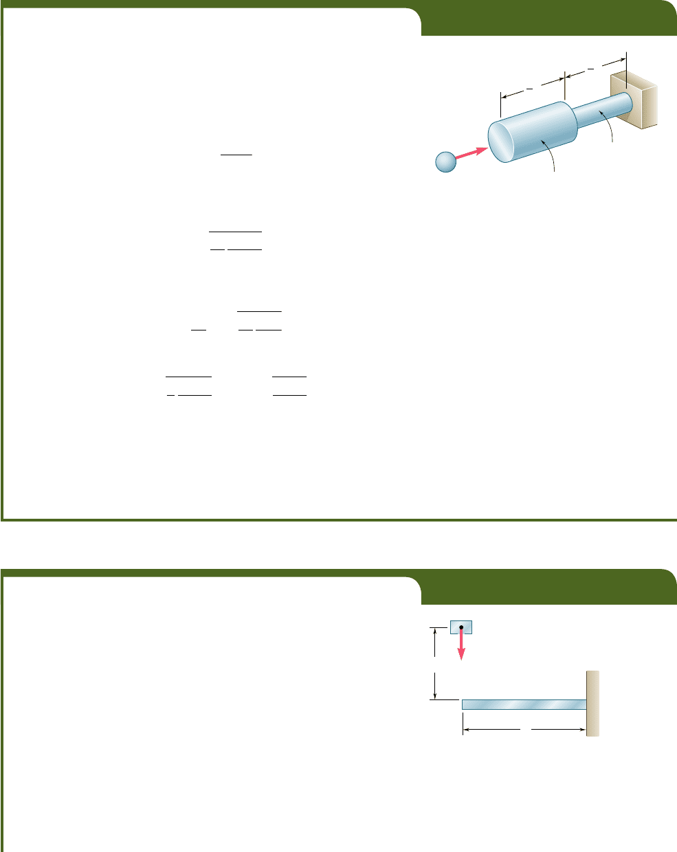
A body of mass m moving with a velocity v
0
hits the end B of the non-
uniform rod BCD (Fig. 11.23). Knowing that the diameter of portion BC
is twice the diameter of portion CD, determine the maximum value s
m
of the stress in the rod.
Making n 5 2 in the expression (11.15) obtained in Example 11.01,
we find that when rod BCD is subjected to a static load P
m
, its strain
energy is
U
m
5
5P
2
m
L
16AE
(11.40)
where A is the cross-sectional area of portion CD of the rod. Solving
Eq. (11.40) for P
m
, we find that the static load that produces in the rod
the same strain energy as the given impact loading is
P
m
5
B
16
5
U
m
AE
L
where U
m
is given by Eq. (11.37). The largest stress occurs in portion CD
of the rod. Dividing P
m
by the area A of that portion, we have
s
m
5
P
m
A
5
B
16
5
U
m
E
A
L
(11.41)
or, substituting for U
m
from Eq. (11.37),
s
m
5
B
8
5
mv
2
0
E
A
L
5 1.265
B
mv
2
0
E
A
L
Comparing this value with the value obtained for s
m
in the case of
the uniform rod of Fig. 11.22 and making V 5 AL in Eq. (11.39), we note
that the maximum stress in the rod of variable cross section is 26.5% larger
than in the lighter uniform rod. Thus, as we observed earlier in our discus-
sion of Example 11.01, increasing the diameter of portion BC of the rod
results in a decrease of the energy-absorbing capacity of the rod.
Area 4A
v
0
B
C
L
A
D
1
2
L
1
2
Fig. 11.23
EXAMPLE 11.07
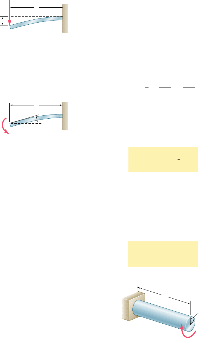
A block of weight W is dropped from a height h onto the free end of the
cantilever beam AB (Fig. 11.24). Determine the maximum value of the
stress in the beam.
As it falls through the distance h, the potential energy Wh of the
block is transformed into kinetic energy. As a result of the impact, the
kinetic energy in turn is transformed into strain energy. We have,
therefore,†
U
m
5 Wh (11.42)
h
A
B
W
L
Fig. 11.24
†The total distance through which the block drops is actually h 1 y
m
, where y
m
is the
maximum deflection of the end of the beam. Thus, a more accurate expression for U
m
(see Sample Prob. 11.3) is
U
m
5 W(h 1 y
m
) (11.429)
However, when h W y
m
, we may neglect y
m
and use Eq. (11.42).
bee80288_ch11_692-758.indd Page 717 11/12/10 5:15:04 PM user-f499bee80288_ch11_692-758.indd Page 717 11/12/10 5:15:04 PM user-f499 /Users/user-f499/Desktop/Temp Work/Don't Delete Job/MHDQ251:Beer:201/ch11/Users/user-f499/Desktop/Temp Work/Don't Delete Job/MHDQ251:Beer:201/ch11

Apago PDF Enhancer
Recalling the expression obtained for the strain energy of the can-
tilever beam AB in Example 11.03 and neglecting the effect of shear, we
write
U
m
5
P
2
m
L
3
6EI
Solving this equation for P
m
, we find that the static force that produces
in the beam the same strain energy is
P
m
5
B
6U
m
EI
L
3
(11.43)
The maximum stress s
m
occurs at the fixed end B and is
s
m
5
0
M
0
c
I
5
P
m
Lc
I
Substituting for P
m
from (11.43), we write
s
m
5
B
6U
m
E
L
1
I
y
c
2
2
(11.44)
or, recalling (11.42),
s
m
5
B
6WhE
L
1
I
y
c
2
2
718
11.8 DESIGN FOR IMPACT LOADS
Let us now compare the values obtained in the preceding section for
the maximum stress s
m
(a) in the rod of uniform cross section of
Fig. 11.22, (b) in the rod of variable cross section of Example 11.06,
and (c) in the cantilever beam of Example 11.07, assuming that the
last has a circular cross section of radius c.
(a) We first recall from Eq. (11.39) that, if U
m
denotes the
amount of energy transferred to the rod as a result of the impact
loading, the maximum stress in the rod of uniform cross section is
s
m
5
B
2U
m
E
V
(11.45a)
where V is the volume of the rod.
(b) Considering next the rod of Example 11.06 and observing
that the volume of the rod is
V 5 4A
1
L
y
2
2
1 A
1
L
y
2
2
5 5AL
y
2
we substitute AL 5 2Vy5 into Eq. (11.41) and write
s
m
5
B
8U
m
E
V
(11.45b)
(c) Finally, recalling that I 5
1
4
pc
4
for a beam of circular cross
section, we note that
L1
I
y
c
2
2
5 L
1
1
4
pc
4
y
c
2
2
5
1
4
1
pc
2
L
2
5
1
4
V
bee80288_ch11_692-758.indd Page 718 11/12/10 5:15:09 PM user-f499bee80288_ch11_692-758.indd Page 718 11/12/10 5:15:09 PM user-f499 /Users/user-f499/Desktop/Temp Work/Don't Delete Job/MHDQ251:Beer:201/ch11/Users/user-f499/Desktop/Temp Work/Don't Delete Job/MHDQ251:Beer:201/ch11

Apago PDF Enhancer
719
where V denotes the volume of the beam. Substituting into Eq.
(11.44), we express the maximum stress in the cantilever beam of
Example 11.07 as
s
m
5
B
24U
m
E
V
(11.45c)
We note that, in each case, the maximum stress s
m
is propor-
tional to the square root of the modulus of elasticity of the material
and inversely proportional to the square root of the volume of the
member. Assuming all three members to have the same volume and
to be of the same material, we also note that, for a given value of
the absorbed energy, the uniform rod will experience the lowest
maximum stress, and the cantilever beam the highest one.
This observation can be explained by the fact that, the distribu-
tion of stresses being uniform in case a, the strain energy will be
uniformly distributed throughout the rod. In case b, on the other
hand, the stresses in portion BC of the rod are only 25% as large as
the stresses in portion CD. This uneven distribution of the stresses
and of the strain energy results in a maximum stress s
m
twice as
large as the corresponding stress in the uniform rod. Finally, in case
c, where the cantilever beam is subjected to a transverse impact
loading, the stresses vary linearly along the beam as well as across a
transverse section. The very uneven resulting distribution of strain
energy causes the maximum stress s
m
to be 3.46 times larger than
if the same member had been loaded axially as in case a.
The properties noted in the three specific cases discussed in
this section are quite general and can be observed in all types of
structures and impact loadings. We thus conclude that a structure
designed to withstand effectively an impact load should
1. Have a large volume
2. Be made of a material with a low modulus of elasticity and a
high yield strength
3. Be shaped so that the stresses are distributed as evenly as pos-
sible throughout the structure
11.9 WORK AND ENERGY UNDER A SINGLE LOAD
When we first introduced the concept of strain energy at the begin-
ning of this chapter, we considered the work done by an axial load
P applied to the end of a rod of uniform cross section (Fig. 11.1).
We defined the strain energy of the rod for an elongation x
1
as the
work of the load P as it is slowly increased from 0 to the value P
1
corresponding to x
1
. We wrote
Strain energy 5 U 5
#
x
1
0
P dx
(11.2)
In the case of an elastic deformation, the work of the load P, and
thus the strain energy of the rod, were expressed as
U 5
1
2
P
1
x
1
(11.3)
11.9 Work and Energy under a Single Load
bee80288_ch11_692-758.indd Page 719 11/12/10 5:15:10 PM user-f499bee80288_ch11_692-758.indd Page 719 11/12/10 5:15:10 PM user-f499 /Users/user-f499/Desktop/Temp Work/Don't Delete Job/MHDQ251:Beer:201/ch11/Users/user-f499/Desktop/Temp Work/Don't Delete Job/MHDQ251:Beer:201/ch11
Apago PDF Enhancer
720
Energy Methods
Later, in Secs. 11.4 and 11.5, we computed the strain energy
of structural members under various loading conditions by determin-
ing the strain-energy density u at every point of the member and
integrating u over the entire member.
However, when a structure or member is subjected to a single
concentrated load, it is possible to use Eq. (11.3) to evaluate its elastic
strain energy, provided, of course, that the relation between the load
and the resulting deformation is known. For instance, in the case of
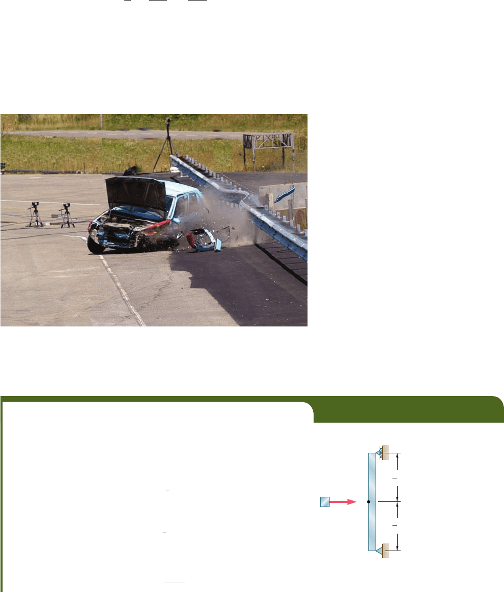
the cantilever beam of Example 11.03 (Fig. 11.25), we write
U 5
1
2
P
1
y
1
and, substituting for y
1
the value obtained from the table of Beam
Deflections and Slopes of Appendix D,
U 5
1
2
P
1
a
P
1
L
3
3EI
b
5
P
2
1
L
3
6EI
(11.46)
A similar approach can be used to determine the strain energy
of a structure or member subjected to a single couple. Recalling that
the elementary work of a couple of moment M is M du, where du is
a small angle, we find, since M and u are linearly related, that the
elastic strain energy of a cantilever beam AB subjected to a single
couple M
1
at its end A (Fig. 11.26) can be expressed as
U 5
#
u
1
0
M du 5
1
2
M
1
u
1
(11.47)
where u
1
is the slope of the beam at A. Substituting for u
1
the value
obtained from Appendix D, we write
U 5
1
2
M
1
a
M
1
L
EI
b
5
M
2
1
L
2EI
(11.48)
In a similar way, the elastic strain energy of a uniform circular
shaft AB of length L subjected at its end B to a single torque T
1
(Fig. 11.27) can be expressed as
U 5
#
f
1
0
T df 5
1
2
T
1
f
1
(11.49)
L
A
B
P
1
y
1
Fig. 11.25 Cantilever beam
with load P
1
.
L
A
B
M
1
1
Fig. 11.26 Cantilever beam
with couple M
1
.
1
T
1
L
A
B
Fig. 11.27 Shaft with Torque T
1
.
bee80288_ch11_692-758.indd Page 720 11/20/10 3:41:23 PM user-f499bee80288_ch11_692-758.indd Page 720 11/20/10 3:41:23 PM user-f499 /Users/user-f499/Desktop/Temp Work/Don't Delete Job/MHDQ251:Beer:201/ch11/Users/user-f499/Desktop/Temp Work/Don't Delete Job/MHDQ251:Beer:201/ch11
Apago PDF Enhancer
721
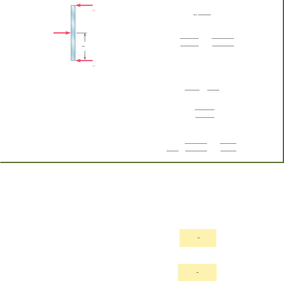
Photo 11.3 As the automobile crashed into the barrier, considerable energy
was dissipated as heat during the permanent deformation of the automobile and
the barrier. Source: Crash test photo courtesy of Sec-Envel and L.I.E.R., France.
11.9 Work and Energy under a Single Load
EXAMPLE 11.08
A block of mass m moving with a velocity v
0
hits squarely the prismatic
member AB at its midpoint C (Fig. 11.28). Determine (a) the equivalent
static load P
m
, (b) the maximum stress s
m
in the member, and (c) the
maximum deflection x
m
at point C.
(a) Equivalent Static Load. The maximum strain energy of the mem-
ber is equal to the kinetic energy of the block before impact. We have
U
m
5
1
2
mv
2
0
(11.50)
On the other hand, expressing U
m
as the work of the equivalent horizontal
static load as it is slowly applied at the midpoint C of the member, we write
U
m
5
1
2
P
m
x
m
(11.51)
where x
m
is the deflection of C corresponding to the static load P
m
. From
the table of Beam Deflections and Slopes of Appendix D, we find that
x
m
5
P
m
L
3
48EI
(11.52)
L
v
0
B
A
C
m
1
2
L
1
2
Fig. 11.28
Substituting for the angle of twist f
1
from Eq. (3.16), we verify
that
U 5
1
2
T
1
a
T
1
L
J
G
b5
T
1
2
L
2
J
G
as previously obtained in Sec. 11.5.
The method presented in this section may simplify the solution
of many impact-loading problems. In Example 11.08, the crash of an
automobile into a barrier (Photo 11.3) is considered by using a sim-
plified model consisting of a block and a simple beam.
bee80288_ch11_692-758.indd Page 721 11/20/10 3:41:30 PM user-f499bee80288_ch11_692-758.indd Page 721 11/20/10 3:41:30 PM user-f499 /Users/user-f499/Desktop/Temp Work/Don't Delete Job/MHDQ251:Beer:201/ch11/Users/user-f499/Desktop/Temp Work/Don't Delete Job/MHDQ251:Beer:201/ch11
Apago PDF Enhancer
Substituting for x
m
from (11.52) into (11.51), we write
U
m
5
1
2
P
2
m
L
3
48EI
Solving for P
m
and recalling Eq. (11.50), we find that the static load
equivalent to the given impact loading is
P
m
5
B
96U
m
EI
L
3
5
B
48mv
2
0
EI
L
3
(11.53)
(b) Maximum Stress. Drawing the free-body diagram of the
member (Fig. 11.29), we find that the maximum value of the bending
moment occurs at C and is M
max
5 P
m
Ly4. The maximum stress, there-
fore, occurs in a transverse section through C and is equal to
s
m
5
M
max
c
I
5
P
m
L
c
4
I
Substituting for P
m
from (11.53), we write
s
m
5
B
3mv
2
0
EI
L
1
I
y
c
2
2
(c) Maximum Deflection. Substituting into Eq. (11.52) the
expression obtained for P
m
in (11.53), we have
x
m
5
L
3
48EI
B
48mv
2
0
EI
L
3
5
B
mv
2
0
L
3
48EI
722
11.10 DEFLECTION UNDER A SINGLE LOAD
BY THE WORK-ENERGY METHOD
We saw in the preceding section that, if the deflection x
1
of a struc-
ture or member under a single concentrated load P
1
is known, the
corresponding strain energy U is obtained by writing
U 5
1
2
P
1
x
1
(11.3)
A similar expression for the strain energy of a structural member
under a single couple M
1
is:
U 5
1
2
M
1
u
1
(11.47)
Conversely, if the strain energy U of a structure or member
subjected to a single concentrated load P
1
or couple M
1
is known,
Eq. (11.3) or (11.47) can be used to determine the corresponding
deflection x
1
or angle u
1
. In order to determine the deflection
under a single load applied to a structure consisting of several com-
ponent parts, it is easier, rather than use one of the methods of
Chap. 9, to first compute the strain energy of the structure by
integrating the strain-energy density over its various parts, as was
done in Secs. 11.4 and 11.5, and then use either Eq. (11.3) or
Eq. (11.47) to obtain the desired deflection. Similarly, the angle of
twist f
1
of a composite shaft can be obtained by integrating the
P
m
B
A
C
L
1
2
P
m
R
B
1
2
P
m
R
A
1
2
Fig. 11.29
bee80288_ch11_692-758.indd Page 722 11/12/10 5:15:22 PM user-f499bee80288_ch11_692-758.indd Page 722 11/12/10 5:15:22 PM user-f499 /Users/user-f499/Desktop/Temp Work/Don't Delete Job/MHDQ251:Beer:201/ch11/Users/user-f499/Desktop/Temp Work/Don't Delete Job/MHDQ251:Beer:201/ch11
Apago PDF Enhancer
723
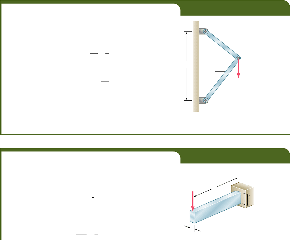
EXAMPLE 11.09
A load P is supported at B by two uniform rods of the same cross-sectional
area A (Fig. 11.30). Determine the vertical deflection of point B.
The strain energy of the system under the given load was deter-
mined in Example 11.02. Equating the expression obtained for U to the
work of the load, we write
U 5 0.364
P
2
l
AE
5
1
2
Py
B
and, solving for the vertical deflection of B,
y
B
5 0.728
P
l
AE
Remark. We should note that, once the forces in the two rods have
been obtained (see Example 11.02), the deformations d
ByC
and d
ByD
of the
rods could be obtained by the method of Chap. 2. Determining the vertical
deflection of point B from these deformations, however, would require a
careful geometric analysis of the various displacements involved. The
strain-energy method used here makes such an analysis unnecessary.
C
D
B
l
P
3
3
4
4
Fig. 11.30
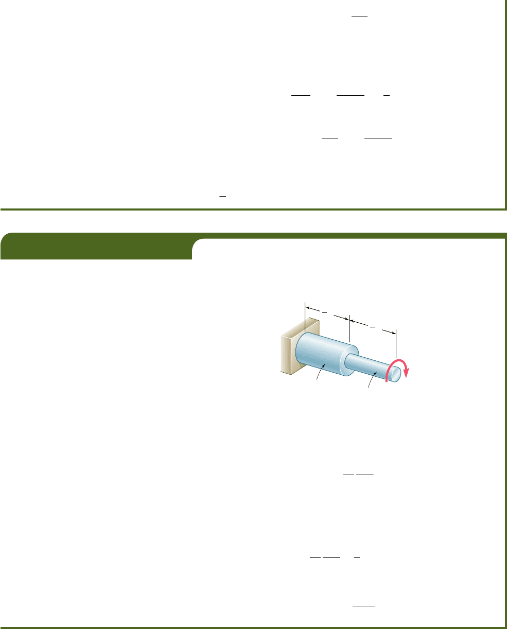
EXAMPLE 11.10
Determine the deflection of end A of the cantilever beam AB (Fig. 11.31),
taking into account the effect of (a) the normal stresses only, (b) both the
normal and shearing stresses.
(a) Effect of Normal Stresses. The work of the force P as it is
slowly applied to A is
U 5
1
2
Py
A
Substituting for U the expression obtained for the strain energy of the
beam in Example 11.03, where only the effect of the normal stresses was
considered, we write
P
2
L
3
6EI
5
1
2
Py
A
strain-energy density over the various parts of the shaft and solving
Eq. (11.49) for f
1
.
It should be kept in mind that the method presented in this
section can be used only if the given structure is subjected to a single
concentrated load or couple. The strain energy of a structure sub-
jected to several loads cannot be determined by computing the work
of each load as if it were applied independently to the structure (see
Sec. 11.11). We can also observe that, even if it were possible to
compute the strain energy of the structure in this manner, only one
equation would be available to determine the deflections correspond-
ing to the various loads. In Secs. 11.12 and 11.13, another method
based on the concept of strain energy is presented, one that can be
used to determine the deflection or slope at a given point of a struc-
ture, even when that structure is subjected simultaneously to several
concentrated loads, distributed loads, or couples.
Fig. 11.31
P
L
A
B
h
b
11.10 Defl ection under a Single Load
by the Work-Energy Method
bee80288_ch11_692-758.indd Page 723 11/12/10 5:15:25 PM user-f499bee80288_ch11_692-758.indd Page 723 11/12/10 5:15:25 PM user-f499 /Users/user-f499/Desktop/Temp Work/Don't Delete Job/MHDQ251:Beer:201/ch11/Users/user-f499/Desktop/Temp Work/Don't Delete Job/MHDQ251:Beer:201/ch11
Apago PDF Enhancer
and, solving for y
A
,
y
A
5
PL
3
3
E
I
(b) Effect of Normal and Shearing Stresses. We now substi-
tute for U the expression (11.24) obtained in Example 11.05, where the
effects of both the normal and shearing stresses were taken into account.
We have
P
2
L
3
6EI
a
1 1
3Eh
2
10GL
2
b
5
1
2
Py
A
and, solving for y
A
,
y
A
5
PL
3
3EI
a
1 1
3Eh
2
10GL
2
b
We note that the relative error when the effect of shear is neglected is
the same that was obtained in Example 11.05, i.e., less than 0.9(hyL)
2
. As
we indicated then, this is less than 0.9% for a beam with a ratio hyL less
than
1
10
.
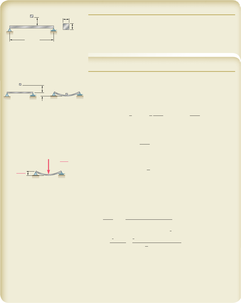
EXAMPLE 11.11
A torque T is applied at the end D of shaft BCD (Fig. 11.32). Knowing
that both portions of the shaft are of the same material and same length,
but that the diameter of BC is twice the diameter of CD, determine the
angle of twist for the entire shaft.
Fig. 11.32
1
2
L
1
2
L
C
D
T
B
diam. 2d
diam. d
The strain energy of a similar shaft was determined in Example
11.04 by breaking the shaft into its component parts BC and CD. Making
n 5 2 in Eq. (11.23), we have
U 5
1
7
32
T
2
L
2G
J
where G is the modulus of rigidity of the material and J the polar moment
of inertia of portion CD of the shaft. Setting U equal to the work of the
torque as it is slowly applied to end D, and recalling Eq. (11.49), we
write
1
7
32
T
2
L
2G
J
5
1
2
Tf
D
y
B
and, solving for the angle of twist f
DyB
,
f
D
y
B
5
1
7
TL
32G
J
724
bee80288_ch11_692-758.indd Page 724 11/12/10 5:15:30 PM user-f499bee80288_ch11_692-758.indd Page 724 11/12/10 5:15:30 PM user-f499 /Users/user-f499/Desktop/Temp Work/Don't Delete Job/MHDQ251:Beer:201/ch11/Users/user-f499/Desktop/Temp Work/Don't Delete Job/MHDQ251:Beer:201/ch11
Apago PDF Enhancer
725
SOLUTION
Principle of Work and Energy. Since the block is released from rest,
we note that in position 1 both the kinetic energy and the strain energy are
zero. In position 2, where the maximum deflection y
m
occurs, the kinetic
energy is again zero. Referring to the table of Beam Deflections and Slopes
of Appendix D, we find the expression for y
m
shown. The strain energy of
the beam in position 2 is
U
2
5
1
2
P
m
y
m
5
1
2
48E
I
L
3
y
2
m
U
2
5
24E
I
L
3
y
2
m
We observe that the work done by the weight W of the block is W(h 1 y
m
).
Equating the strain energy of the beam to the work done by W, we have
24E
I
L
3
y
2
m
5 W1h 1 y
m
2
(1)
a. Maximum Deflection of Point C. From the given data we have
EI 5
1
73 3 10
9
Pa
2
1
12
1
0.04 m
2
4
5 15.573 3 10
3
N ? m
2
L 5
1
m
h
5 0.040 m W 5 mg 5 180 kg219.81 m/s
2
25 784.8 N
Substituting into Eq. (1), we obtain and solve the quadratic equation
1373.8 3 10
3
2y
2
m
2 784.8y
m
2 31.39 5 0 y
m
5 10.27 mm
◀
b. Maximum Stress. The value of P
m
is
P
m
5
48EI
L
3
y
m
5
48115.573 3 10
3
N ? m2
1
1 m
2
3
10.01027 m2
P
m
5 7677 N
Recalling that s
m
5 M
max
c/I and M
max
5
1
4
P
m
L, we write
s
m
5
1
1
4
P
m
L2c
I
5
1
4
17677 N211 m210.020 m2
1
12
1
0.040 m
2
4
s
m
5 179.9 MPa
◀
An approximation for the work done by the weight of the block can be
obtained by omitting y
m
from the expression for the work and from the
right-hand member of Eq. (1), as was done in Example 11.07. If this approx-
imation is used here, we find y
m
5 9.16 mm; the error is 10.8%. However,
if an 8-kg block is dropped from a height of 400 mm, producing the same
value of Wh, omitting y
m
from the right-hand member of Eq. (1) results in
an error of only 1.2%. A further discussion of this approximation is given in
Prob. 11.70.
SAMPLE PROBLEM 11.3
The block D of mass m is released from rest and falls a distance h before
it strikes the midpoint C of the aluminum beam AB. Using E 5 73 GPa,
determine (a) the maximum deflection of point C, (b) the maximum stress
that occurs in the beam.
A
L 1 m
B
D
C
m 80 kg
h 40 mm
40 mm
40 mm
A
Position 1 Position 2
A
BB
h
y
m
D
D
A
B
C
P
m
L
3
48EI
y
m
48EI
L
3
P
m
y
m
From Appendix D
bee80288_ch11_692-758.indd Page 725 11/19/10 11:34:21 PM user-f499bee80288_ch11_692-758.indd Page 725 11/19/10 11:34:21 PM user-f499 /Users/user-f499/Desktop/Temp Work/Don't Delete Job/MHDQ251:Beer:201/ch11/Users/user-f499/Desktop/Temp Work/Don't Delete Job/MHDQ251:Beer:201/ch11
Apago PDF Enhancer
726
SOLUTION
Axial Forces in Truss Members. The reactions are found by using
the free-body diagram of the entire truss. We then consider in sequence the
equilibrium of joints, E, C, D, and B. At each joint we determine the forces
indicated by dashed lines. At joint B, the equation oF
x
5 0 provides a check
of our computations.
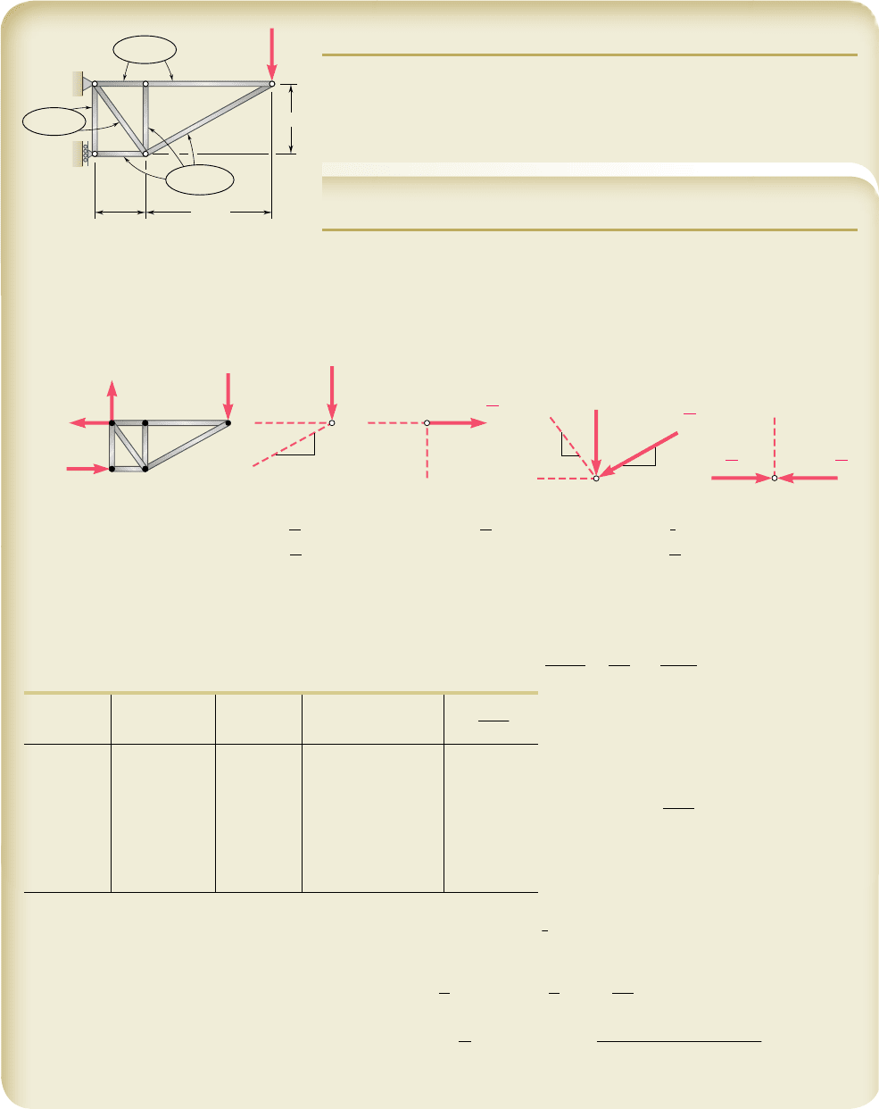
SAMPLE PROBLEM 11.4
Members of the truss shown consist of sections of aluminum pipe with the
cross-sectional areas indicated. Using E 5 73 GPa, determine the vertical
deflection of point E caused by the load P.
500 mm
2
0.8 m
0.6 m
1.5 m
P 40 kN
A
C
E
B
D
500 mm
2
1000 mm
2
A
B
E
17
17
8
8
4
5
3
15
8
15
15
E
C
D
B 21P/8
A
x
21P/8
P
A
y
P
F
CE
F
AC
F
CE
F
CD
0
F
AD
F
BD
P
F
CD
F
DE
17
8
F
DE
P
21
8
F
BD
F
AB
P
21
8
B P
B
P
oF
y
5 0: F
DE
52
17
8
P oF
x
5 0: F
AC
51
15
8
P oF
y
5 0: F
AD
51
5
4
P
o
F
y
5 0: F
AB
5 0
oF
x
5 0: F
CE
51
15
8
P
o
F
y
5 0: F
CD
5 0 oF
x
5 0: F
BD
52
21
8
P oF
x
5 0:
1
Checks
2
Strain Energy. Noting that E is the same for all members, we express
the strain energy of the truss as follows
U 5
a
F
2
i
L
i
2A
i
E
5
1
2E
a
F
2
i
L
i
A
i
(1)
where F
i
is the force in a given member
as indicated in the following table and
where the summation is extended over all
members of the truss.
a
F
i
2
L
i
A
i
5 29 700P
2
Returning to Eq. (1), we have
U 5
1
1
y
2E
21
29.7 3 10
3
P
2
2
.
Principle of Work-Energy. We recall that the work done by the load
P as it is gradually applied is
1
2
Py
E
. Equating the work done by P to the
strain energy U and recalling that E 5 73 GPa and P 5 40 kN, we have
1
2
Py
E
5 U
1
2
Py
E
5
1
2
E
129.7 3 10
3
P
2
2
y
E
5
1
E
129.7 3 10
3
P25
129.7 3 10
3
2140 3 10
3
2
73 3 10
9
y
E
5 16.27 3 10
2
3
m y
E
5 16.27 mmw
◀
Member F
i
L
i
, m A
i
, m
2
F
i
2
L
i
A
i
AB 0 0.8 500 3 10
26
0
AC 115Py8 0.6 500 3 10
26
4 219P
2
AD 15Py4 1.0 500 3 10
26
3 125P
2
BD 221Py8 0.6 1000 3 10
26
4 134P
2
CD 0 0.8 1000 3 10
26
0
CE 115Py8 1.5 500 3 10
26
10 547P
2
DE 217Py8 1.7 1000 3 10
26
7 677P
2
bee80288_ch11_692-758.indd Page 726 11/20/10 3:41:35 PM user-f499bee80288_ch11_692-758.indd Page 726 11/20/10 3:41:35 PM user-f499 /Users/user-f499/Desktop/Temp Work/Don't Delete Job/MHDQ251:Beer:201/ch11/Users/user-f499/Desktop/Temp Work/Don't Delete Job/MHDQ251:Beer:201/ch11
