Beer F.P., Johnston E.R., DeWolf J.T., Mazurek D.F. Mechanics of Materials
Подождите немного. Документ загружается.

Apago PDF Enhancer
677
centric loading of Fig. 10.34a and to the pure bending of
Fig. 10.34b. We have
P
y
A
1s
all
2
centric
1
Mc
y
I
1s
all
2
bendin
g
# 1
(10.55)
The type of formula obtained is known as an interaction formula.
We note that, when M 5 0, the use of this formula results in
the design of a centrically loaded column by the method of Sec. 10.6.
On the other hand, when P 5 0, the use of the formula results in
the design of a beam in pure bending by the method of Chap. 4.
When P and M are both different from zero, the interaction formula
results in a design that takes into account the capacity of the member
to resist bending as well as axial loading. In all cases, (s
all
)
centric
will
be determined by using the largest slenderness ratio of the column,
regardless of the plane in which bending takes place.†
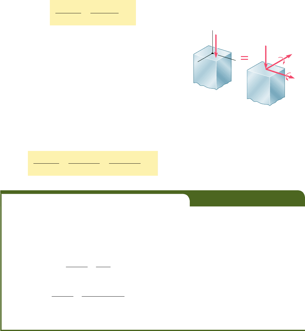
When the eccentric load P is not applied in a plane of sym-
metry of the column, it causes bending about both of the principal
axes of the cross section. We recall from Sec. 4.14 that the load P
can then be replaced by a centric load P and two couples repre-
sented by the couple vectors M
x
and M
z
shown in Fig. 10.35. The
interaction formula to be used in this case is
P
y
A
1s
all
2
centric
1
ƒ M
x
ƒ z
max
y
I
x
1s
all
2
bendin
g
1
ƒ M
z
ƒ x
max
y
I
z
1s
all
2
bendin
g
# 1
(10.56)
10.7 Design of Columns under an
Eccentric Load
†This procedure is required by all major codes for the design of steel, aluminum, and
timber compression members. In addition, many specifications call for the use of an
additional factor in the second term of Eq. (10.55); this factor takes into account the
additional stresses resulting from the deflection of the column due to bending.
EXAMPLE 10.05
Use the interaction method to determine the maximum load P that can
be safely supported by the column of Example 10.04 with an eccentricity
of 0.8 in. The allowable stress in bending is 24 ksi.
The value of (s
all
)
centric
has already been determined in Example
10.04. We have
1
s
all
2
centric
5 19.79 ksi
1
s
all
2
bending
5 24 ksi
Substituting these values into Eq. (10.55), we write
P
y
A
19
.
79 k
s
i
1
Mc
y
I
24 k
s
i
# 1.0
Using the numerical data from Example 10.04, we write
P
y
4
19
.
79 k
s
i
1
P
1
0.8
21
1.0
2
y
1.33
3
24 k
s
i
# 1.0
P # 26.6
k
ips
The maximum load that can be safely applied is thus P 5 26.6 kips.
C
y
z
M
z
M
x
C
x
P
P
Fig. 10.35 Column with eccentric load.
bee80288_ch10_630-691.indd Page 677 11/1/10 2:38:38 PM user-f499bee80288_ch10_630-691.indd Page 677 11/1/10 2:38:38 PM user-f499/Users/user-f499/Desktop/Temp Work/Don't Delete Job/MHDQ251:Beer:201/ch10/Users/user-f499/Desktop/Temp Work/Don't Delete Job/MHDQ251:Beer:201/ch
Apago PDF Enhancer
678
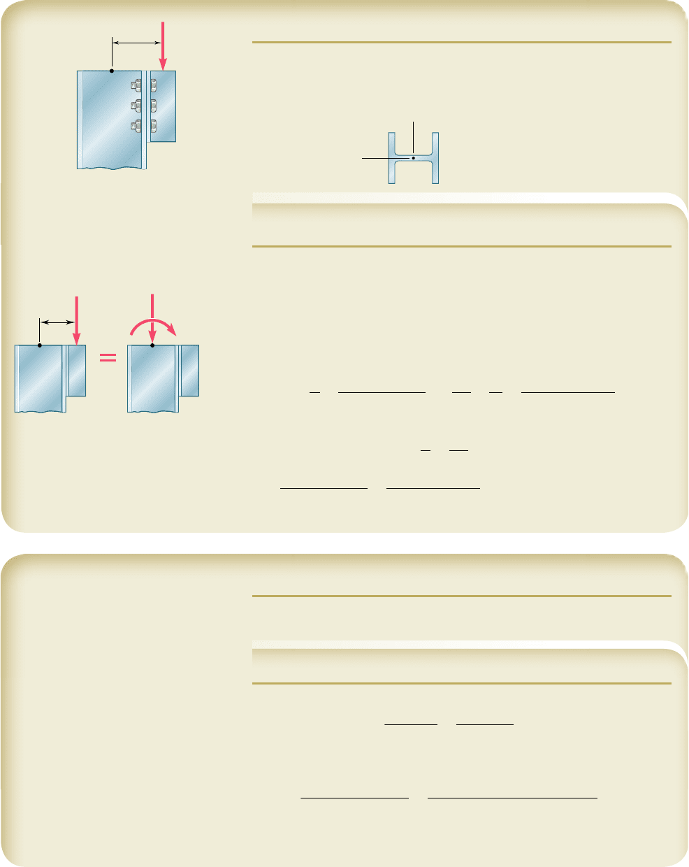
SAMPLE PROBLEM 10.5
Using the allowable-stress method, determine the largest load P that can be
safely carried by a W310 3 74 steel column of 4.5-m effective length. Use
E 5 200 GPa and s
Y
5 250 MPa.
SOLUTION
The largest slenderness ratio of the column is Lyr
y
5 (4.5 m)y(0.0498 m) 5
90.4. Using Eq. (10.41) with E 5 200 GPa and s
Y
5 250 MPa, we find that
the slenderness ratio at the junction between the two equations for s
cr
is
Lyr 5 133.2. Thus, we use Eqs. (10.38) and (10.39) and find that s
cr
5
162.2 MPa. Using Eq. (10.42), the allowable stress is
1
s
all
2
centric
5 162.2
y
1.67 5 97.1 MPa
For the given column and loading, we have
P
A
5
P
9
.
42 3 10
23
m
2
Mc
I
5
M
S
5
P
1
0.200 m
2
1
.
050 3 10
23
m
3
Substituting into Eq. (10.58), we write
P
A
1
M
c
I
# s
all
P
9
.
42 3 10
23
m
2
1
P
1
0.200 m
2
1.050 3 10
23
m
3
# 97.1 MPa
P # 327
k
N
The largest allowable load P is thus P 5 327 kNw
◀
200 mm
C
P
y
x
C
W310 ⫻ 74
A ⫽ 9420 mm
2
r
x
⫽ 132 mm
S
x
⫽ 1050 ⫻ 10
3
mm
3
r
y
⫽ 49.8 mm
200 mm
C
C
M ⫽ P(0.200 m)
P
P
SAMPLE PROBLEM 10.6
Using the interaction method, solve Sample Prob. 10.5. Assume (s
all
)
bending
5
150 MPa.
SOLUTION
Using Eq. (10.60), we write
P
y
A
1s
all
2
centric
1
Mc
y
I
1s
all
2
bending
# 1
Substituting the given allowable bending stress and the allowable centric
stress found in Sample Prob. 10.5, as well as the other given data, we have
P
y
19.42 3 10
23
m
2
2
97
.
1 3 10
6
P
a
1
P10.200 m2
y
11.050 3 10
23
m
3
2
150 3 10
6
P
a
# 1
P # 423
k
N
The largest allowable load P is thus P = 423 kNw
◀
bee80288_ch10_630-691.indd Page 678 11/20/10 2:57:51 PM user-f499bee80288_ch10_630-691.indd Page 678 11/20/10 2:57:51 PM user-f499 /Users/user-f499/Desktop/Temp Work/Don't Delete Job/MHDQ251:Beer:201/ch10/Users/user-f499/Desktop/Temp Work/Don't Delete Job/MHDQ251:Beer:201/ch10
Apago PDF Enhancer
679
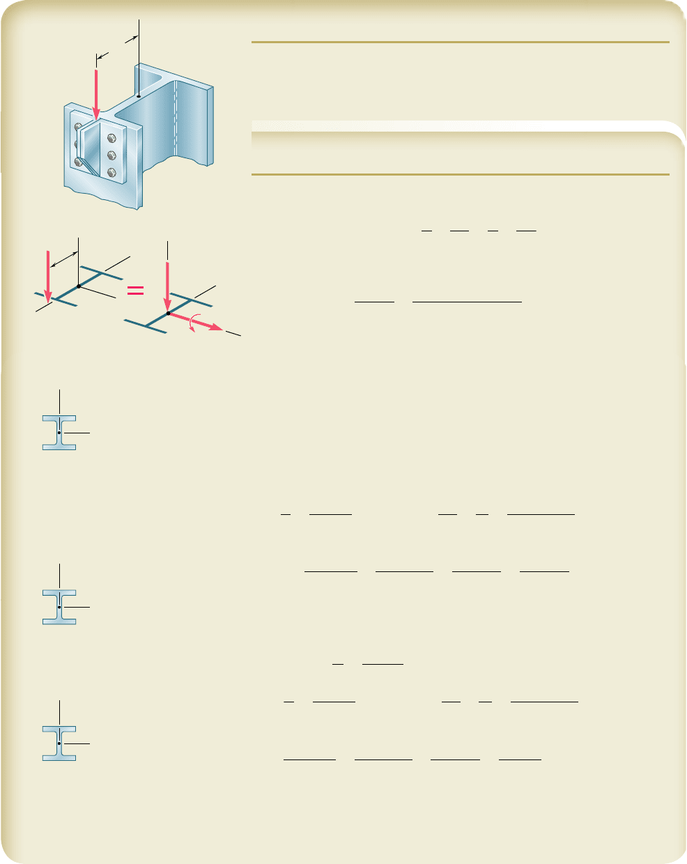
SAMPLE PROBLEM 10.7
A steel column having an effective length of 16 ft is loaded eccentrically as
shown. Using the interaction method, select the wide-flange shape of 8-in.
nominal depth that should be used. Assume E 5 29 3 10
6
psi and s
Y
5 36 ksi,
and use an allowable stress in bending of 22 ksi.
SOLUTION
So that we can select a trial section, we use the allowable-stress method with
s
all
5 22 ksi and write
s
all
5
P
A
1
M
c
I
x
5
P
A
1
M
c
Ar
2
x
(1)
From Appendix C we observe for shapes of 8-in. nominal depth that
c
<
4
in
.
and r
x
< 3.5 in. Substituting into Eq. (1), we have
22 ksi 5
85 kips
A
1
1
425 kip ? in.
21
4 in.
2
A
1
3.5 in.
2
2
A
< 10.2 in
2
We select for a first trial shape: W8 3 35.
Trial 1: W8 3 35. The allowable stresses are
Allowable Bending Stress: (see data)
1
s
all
2
bending
5 22 ksi
Allowable Concentric Stress: The largest slenderness ratio of the column
is Lyr
y
5 (192 in.)y(2.03 in.) 5 94.6. Using Eq. (10.41) with E 5 29 3 10
6
psi
and s
Y
5 36 ksi, we find that the slenderness ratio at the junction between
the two equations for s
cr
is Lyr 5 133.7. Thus, we use Eqs. (10.38) and (10.39)
and find that s
cr
5 22.5 ksi. Using Eq. (10.42), the allowable stress is
1
s
all
2
centric
5 22.5
y
1.67 5 13.46 ksi
For the W8 3 35 trial shape, we have
P
A
5
85
k
ips
10
.
3 in
2
5 8.25 ksi
Mc
I
5
M
S
x
5
425
k
ip ? in.
31.2 in
3
5 13.62 ksi
With this data we find that the left-hand member of Eq. (10.60) is
P
y
A
1s
all
2
centric
1
Mc
y
I
1s
all
2
bending
5
8.25 ksi
13.46 ksi
1
13.62 ksi
22 ksi
5 1.232
Since 1.232 . 1.000, the requirement expressed by the interaction formula
is not satisfied; we must select a larger trial shape.
Trial 2: W8 3 48. Following the procedure used in trial 1, we write
L
r
y
5
192
in.
2.08 in.
5 92.3
1
s
all
2
centric
5 13.76 ksi
P
A
5
85
k
ips
14
.
1 in
2
5 6.03 ksi
Mc
I
5
M
S
x
5
425
k
ip ? in.
43.2 in
3
5 9.84 ksi
Substituting into Eq. (10.60) gives
P
y
A
1s
all
2
centric
1
Mc
y
I
1s
all
2
bending
5
6.03 ksi
13.76 ksi
1
9.82 ksi
22 ksi
5 0.885 , 1.000
The W8 3 48 shape is satisfactory but may be unnecessarily large.
Trial 3: W8 3 40. Following again the same procedure, we find that
the interaction formula is not satisfied.
Selection of Shape. The shape to be used is W8 3 48
◀
C
5 in.
P ⫽ 85 kips
5 in.
P ⫽ 85 kips
C
z
x
y
P ⫽ 85 kips
M ⫽ (85 kips)(5 in.)
⫽ 425 kip · in.
C
z
x
y
y
x
C
W8 ⫻ 35
A ⫽ 10.3 in
2
r
x
⫽ 3.51 in.
r
y
⫽ 2.03 in.
S
x
⫽ 31.2 in
3
L ⫽ 16 ft ⫽ 192 in.
y
x
C
W8 ⫻ 48
A ⫽ 14.1 in
2
r
x
⫽ 3.61 in.
r
y
⫽ 2.08 in.
S
x
⫽ 43.2 in
3
L ⫽ 16 ft ⫽ 192 in.
y
x
C
W8 ⫻ 40
A ⫽ 11.7 in
2
r
x
⫽ 3.53 in.
r
y
⫽ 2.04 in.
S
x
⫽ 35.5 in
3
L ⫽ 16 ft ⫽ 192 in.
bee80288_ch10_630-691.indd Page 679 11/20/10 2:57:59 PM user-f499bee80288_ch10_630-691.indd Page 679 11/20/10 2:57:59 PM user-f499 /Users/user-f499/Desktop/Temp Work/Don't Delete Job/MHDQ251:Beer:201/ch10/Users/user-f499/Desktop/Temp Work/Don't Delete Job/MHDQ251:Beer:201/ch10
Apago PDF Enhancer
PROBLEMS
680
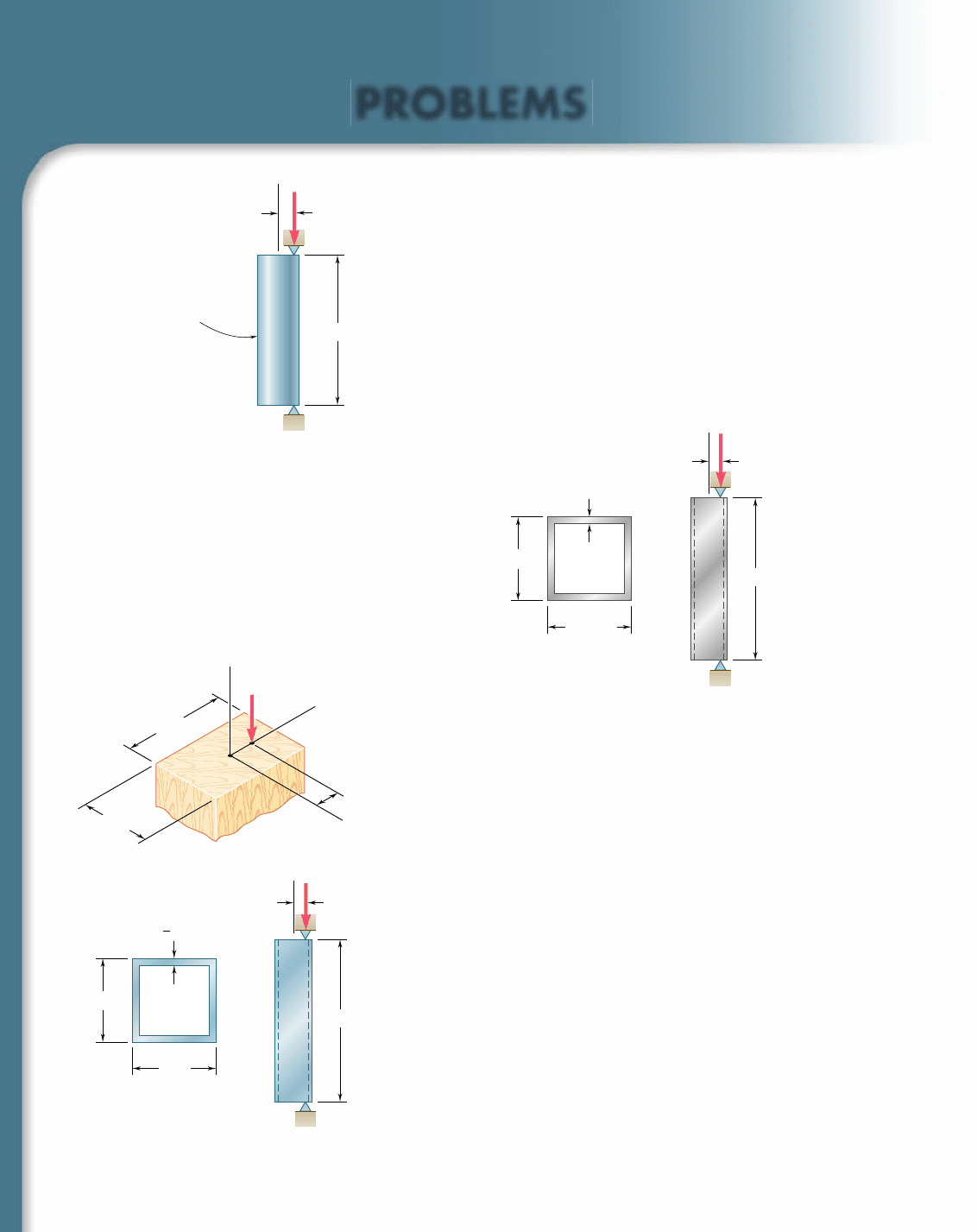
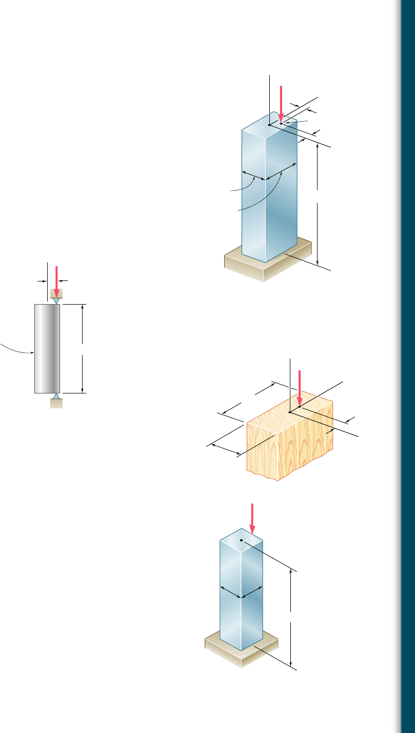
10.89 An eccentric load is applied at a point 22 mm from the geometric
axis of a 60-mm-diameter rod made of a steel for which s
Y
5
250 MPa and E 5 200 GPa. Using the allowable-stress method,
determine the allowable load P.
10.90 Solve Prob. 10.89, assuming that the load is applied at a point 40 mm
from the geometric axis and that the effective length is 0.9 m.
10.91 A column of 5.5-m effective length is made of the aluminum alloy
2014-T6, for which the allowable stress in bending is 220 MPa.
Using the interaction method, determine the allowable load P,
knowing that the eccentricity is (a) e 5 0, (b) e 5 40 mm.
22 mm
60 mm diameter
1.2 m
A
B
P
Fig. P10.89
e
152 mm
152 mm
15 mm
5.5 m
A
B
P
Fig. P10.91
10.92 Solve Prob. 10.91, assuming that the effective length of the column
is 3.0 m.
10.93 A sawn-lumber column of 5.0 3 7.5-in. cross section has an effec-
tive length of 8.5 ft. The grade of wood used has an adjusted allow-
able stress for compression parallel to the grain s
C
5 1180 psi and
an adjusted modulus E 5 440 3 10
3
psi. Using the allowable-stress
method, determine the largest eccentric load P that can be applied
when (a) e 5 0.5 in., (b) e 5 1.0 in.
10.94 Solve Prob. 10.93 using the interaction method and an allowable
stress in bending of 1300 psi.
10.95 A column of 14-ft effective length consists of a section of steel
tubing having the cross section shown. Using the allowable-stress
method, determine the maximum allowable eccentricity e if
(a) P 5 55 kips, (b) P 5 35 kips. Use s
Y
5 36 ksi and E 5
29 3 10
6
psi.
10.96 Solve Prob. 10.95, assuming that the effective length of the column
is increased to 18 ft and that (a) P 5 28 kips, (b) P 5 18 kips.
e
x
y
z
C
D
7.5 in.
5.0 in.
P
Fig. P10.93
e
4 in.
4 in.
3
8
in.
14 ft
A
B
P
Fig. P10.95
bee80288_ch10_630-691.indd Page 680 11/1/10 2:39:01 PM user-f499bee80288_ch10_630-691.indd Page 680 11/1/10 2:39:01 PM user-f499/Users/user-f499/Desktop/Temp Work/Don't Delete Job/MHDQ251:Beer:201/ch10/Users/user-f499/Desktop/Temp Work/Don't Delete Job/MHDQ251:Beer:201/ch
Apago PDF Enhancer
681
Problems
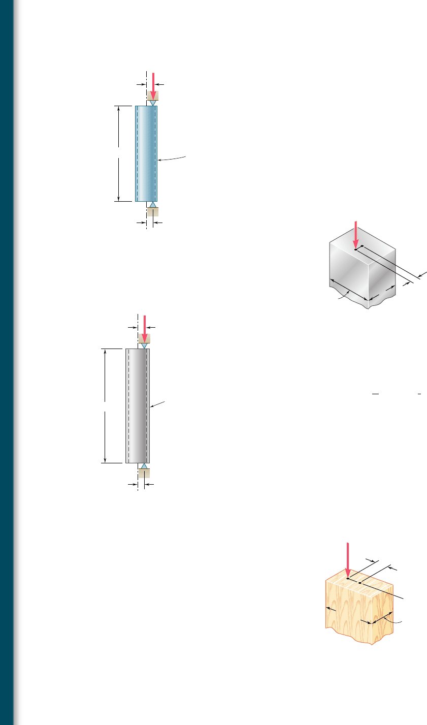
10.97 The compression member AB is made of a steel for which s
Y
5
250 MPa and E 5 200 GPa. It is free at its top A and fixed at its
base B. Using the allowable-stress method, determine the largest
allowable eccentricity e
x
, knowing that (a) e
y
5 0, (b) e
y
5 8 mm.
10.98 The compression member AB is made of a steel for which s
Y
5
250 MPa and E 5 200 GPa. It is free at its top A and fixed at its
base B. Using the interaction method with an allowable bending
stress equal to 120 MPa and knowing that the eccentricities e
x
and
e
y
are equal, determine their largest allowable common value.
10.99 An eccentric load P 5 10 kips is applied at a point 0.8 in. from
the geometric axis of a 2-in.-diameter rod made of the aluminum
alloy 6061-T6. Using the interaction method and an allowable
stress in bending of 21 ksi, determine the largest allowable effec-
tive length L that can be used.
0.55 m
50 mm
75 mm
A
C
z
x
y
e
x
e
y
D
B
P 170 kN
Fig. P10.97 and P10.98
P 10 kips
0.8 in.
2 in. diameter
L
A
B
Fig. P10.99
10.100 Solve Prob. 10.99, assuming that the aluminum alloy used is 2014-
T6 and that the allowable stress in bending is 24 ksi.
10.101 A rectangular column is made of a grade of sawn wood that has
an adjusted allowable stress for compression parallel to the grain
s
C
5 8.3 MPa and an adjusted modulus of elasticity E 5 11.1 GPa.
Using the allowable-stress method, determine the largest allowable
effective length L that can be used.
10.102 Solve Prob. 10.101, assuming that P 5 105 kN.
10.103 An 11-kip vertical load P is applied at the midpoint of one edge
of the square cross section of the steel compression member AB,
which is free at its top A and fixed at its base B. Knowing that for
the grade of steel used s
Y
5 36 ksi and E 5 29 3 10
6
psi. and using
the allowable-stress method, determine the smallest allowable
dimension d.
10.104 Solve Prob. 10.103, assuming that the vertical load P is applied at
the corner of the cross section.
P 85 kN
C
D
z
y
240 mm
180 mm
x
25 mm
Fig. P10.101
4.5 ft
d
d
P 11 kips
A
D
B
Fig. P10.103
bee80288_ch10_630-691.indd Page 681 11/1/10 2:39:12 PM user-f499bee80288_ch10_630-691.indd Page 681 11/1/10 2:39:12 PM user-f499/Users/user-f499/Desktop/Temp Work/Don't Delete Job/MHDQ251:Beer:201/ch10/Users/user-f499/Desktop/Temp Work/Don't Delete Job/MHDQ251:Beer:201/ch
Apago PDF Enhancer
682
Columns
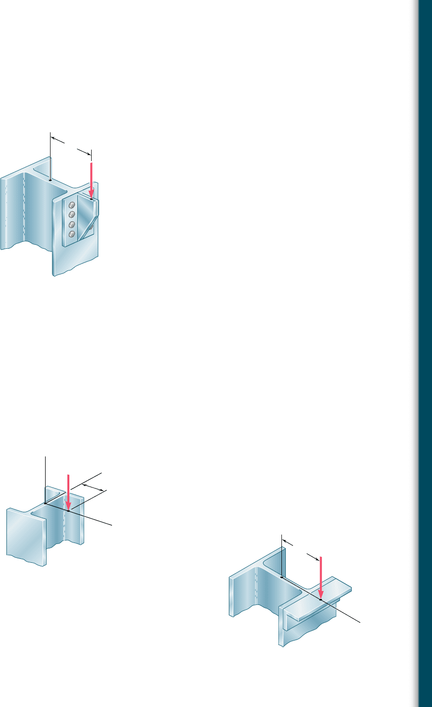
10.105 A steel tube of 80-mm outer diameter is to carry a 93-kN load P
with an eccentricity of 20 mm. The tubes available for use are made
with wall thicknesses in increments of 3 mm from 6 mm to 15 mm.
Using the allowable-stress method, determine the lightest tube that
can be used. Assume E 5 200 GPa and s
Y
5 250 MPa.
10.106 Solve Prob. 10.105, using the interaction method with P 5 165 kN,
e 5 15 mm, and an allowable stress in bending of 150 MPa.
10.107 A compression member of rectangular cross section has an effec-
tive length of 0.9 m and is made of the aluminum alloy 2014-T6
for which the allowable stress in bending is 160 MPa. Using the
interaction method, determine the smallest dimension d of the
cross section that can be used when e 5 10 mm.
10.108 Solve Prob. 10.107, assuming that e 5 5 mm.
10.109 An aluminum tube of 3-in. outside diameter is to carry a load of
10 kips having an eccentricity e 5 0.6 in. Knowing that the stock
of tubes available for use are made of alloy 2014-T6 and have wall
thicknesses in increments of
1
16
in. up to
1
2
in. determine the lightest
tube that can be used. Use the allowable-stress method.
10.110 Solve Prob. 10.109, using the interaction method of design with an
allowable stress in bending of 25 ksi.
10.111 A sawn lumber column of rectangular cross section has a 2.2-m
effective length and supports a 41-kN load as shown. The sizes
available for use have b equal to 90 mm, 140 mm, 190 mm, and
240 mm. The grade of wood has an adjusted allowable stress for
compression parallel to the grain s
C
5 8.1 MPa and an adjusted
modulus E 5 8.3 GPa. Using the allowable-stress method, deter-
mine the lightest section that can be used.
2.2 m
80-mm oute
r
diameter
A
B
e
e 20 mm
P
Fig. P10.105
d
C
D
P 144 kN
e
56 mm
Fig. P10.107
10.112 Solve Prob. 10.111, assuming that e 5 40 mm.
e 0.6 in.
e
3-in. outside
diameter
B
A
6 ft
P 10 kips
Fig. P10.109
41 kN
D
C
190 mm
e 80 mm
b
Fig. P10.111
bee80288_ch10_630-691.indd Page 682 11/1/10 2:39:21 PM user-f499bee80288_ch10_630-691.indd Page 682 11/1/10 2:39:21 PM user-f499/Users/user-f499/Desktop/Temp Work/Don't Delete Job/MHDQ251:Beer:201/ch10/Users/user-f499/Desktop/Temp Work/Don't Delete Job/MHDQ251:Beer:201/ch
Apago PDF Enhancer
683
Problems
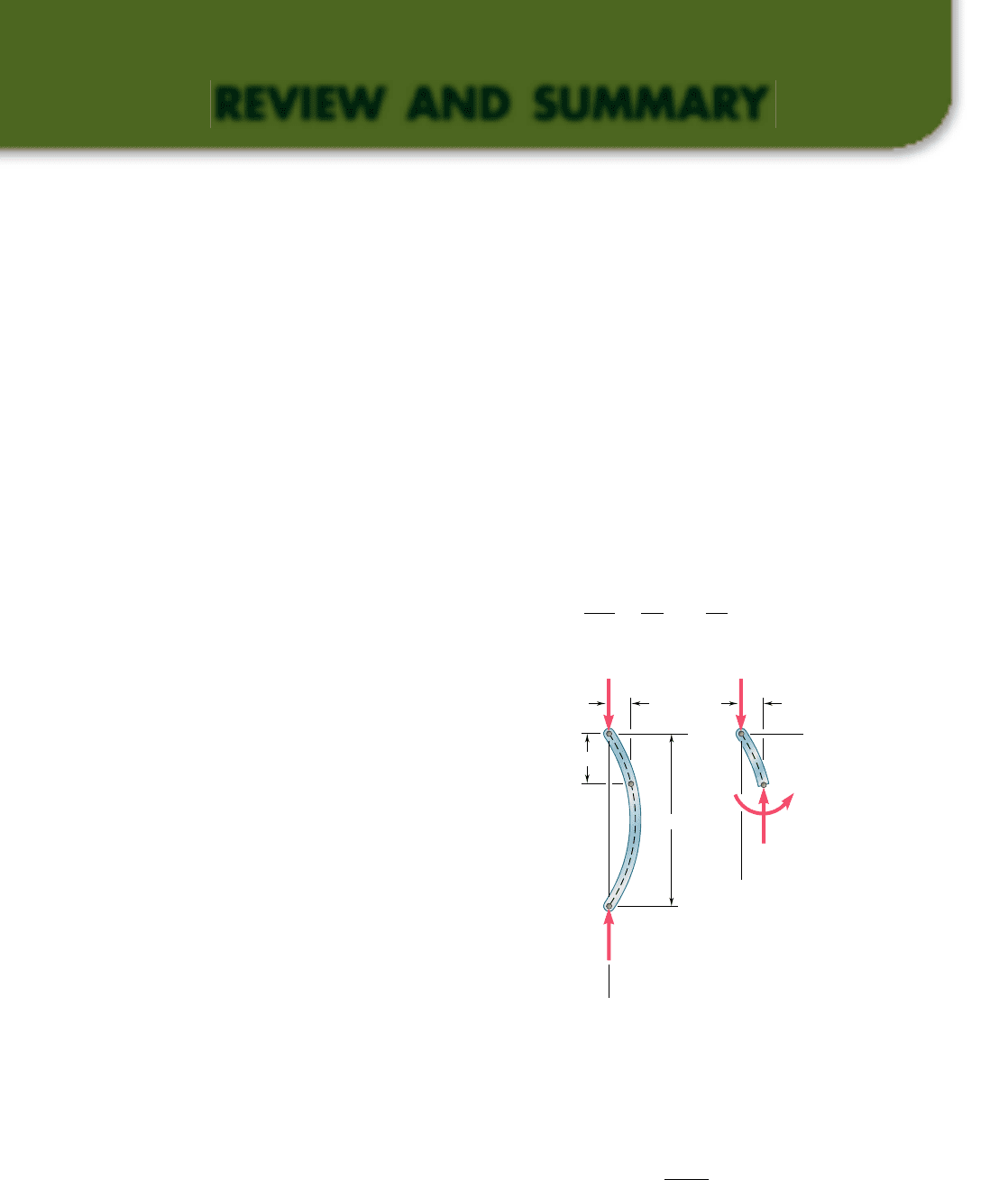
10.113 A steel column having a 24-ft effective length is loaded eccentri-
cally as shown. Using the allowable-stress method, select the wide-
flange shape of 14-in. nominal depth that should be used. Use
s
Y
5 36 ksi and E 5 29 3 10
6
psi.
10.114 Solve Prob. 10.113 using the interaction method, assuming that
s
Y
5 50 ksi and the allowable stress in bending is 30 ksi.
10.115 A steel column of 7.2-m effective length is to support an 83-kN
eccentric load P at a point D, located on the x axis as shown. Using
the allowable-stress method, select the wide-flange shape of
250-mm nominal depth that should be used. Use E 5 200 GPa and
s
Y
5 250 MPa.
P 120 kips
8 in.
C
D
Fig. P10.113
C
y
x
z
e
x
70 mm
P
D
Fig. P10.115
C
D
125 mm
P
Fig. P10.116
10.116 A steel compression member of 5.8-m effective length is to support a
296-kN eccentric load P. Using the interaction method, select the
wide-flange shape of 200-mm nominal depth that should be used. Use
E 5 200 GPa, s
Y
5 250 MPa, and s
all
5 150 MPa in bending.
bee80288_ch10_630-691.indd Page 683 11/1/10 2:39:30 PM user-f499bee80288_ch10_630-691.indd Page 683 11/1/10 2:39:30 PM user-f499/Users/user-f499/Desktop/Temp Work/Don't Delete Job/MHDQ251:Beer:201/ch10/Users/user-f499/Desktop/Temp Work/Don't Delete Job/MHDQ251:Beer:201/ch
Apago PDF Enhancer
684
REVIEW AND SUMMARY
This chapter was devoted to the design and analysis of columns, i.e.,
prismatic members supporting axial loads. In order to gain insight
into the behavior of columns, we first considered in Sec. 10.2 the
equilibrium of a simple model and found that for values of the load
P exceeding a certain value P
cr
, called the critical load, two equilib-
rium positions of the model were possible: the original position with
zero transverse deflections and a second position involving deflec-
tions that could be quite large. This led us to conclude that the first
equilibrium position was unstable for P . P
cr
, and stable for P , P
cr
,
since in the latter case it was the only possible equilibrium
position.
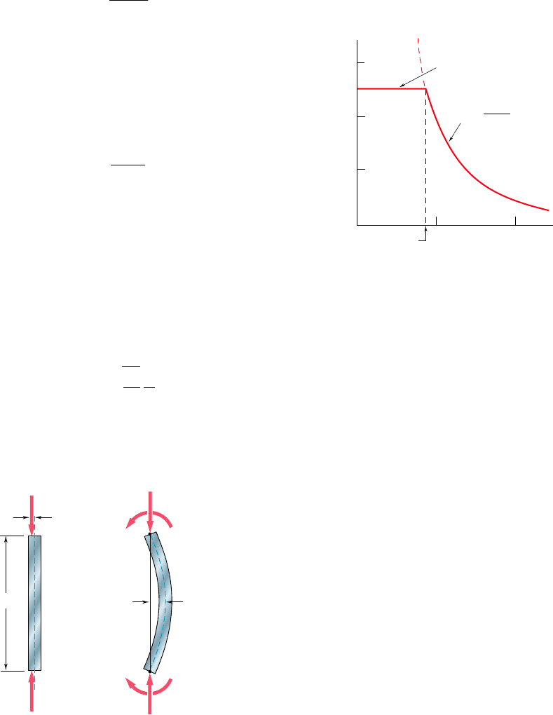
In Sec. 10.3, we considered a pin-ended column of length L and of
constant flexural rigidity EI subjected to an axial centric load P.
Assuming that the column had buckled (Fig. 10.36), we noted that
the bending moment at point Q was equal to 2Py and wrote
d
2
y
d
x
2
5
M
EI
52
P
EI
y
(10.4)
Critical load
Euler’s formula
L
Q
Q
B
A
A
x
y
y
x
x
y
P'
P'
M
y
[ x 0, y 0]
[ x L, y 0]
(a)(b)
P P
Fig. 10.36
Solving this differential equation, subject to the boundary conditions
corresponding to a pin-ended column, we determined the smallest
load P for which buckling can take place. This load, known as the
critical load and denoted by P
cr
, is given by Euler’s formula:
P
cr
5
p
2
EI
L
2
(10.11)
bee80288_ch10_630-691.indd Page 684 11/19/10 12:58:36 AM user-f499bee80288_ch10_630-691.indd Page 684 11/19/10 12:58:36 AM user-f499 /Users/user-f499/Desktop/Temp Work/Don't Delete Job/MHDQ251:Beer:201/ch10/Users/user-f499/Desktop/Temp Work/Don't Delete Job/MHDQ251:Beer:201/ch10
Apago PDF Enhancer
685
where L is the length of the column. For this load or any larger load,
the equilibrium of the column is unstable and transverse deflections
will occur.
Denoting the cross-sectional area of the column by A and its
radius of gyration by r, we determined the critical stress s
cr
corre-
sponding to the critical load P
cr
:
s
cr
5
p
2
E
1L
y
r2
2
(10.13)
The quantity Lyr is called the slenderness ratio and we plotted s
cr
as a function of Lyr (Fig. 10.37). Since our analysis was based on
stresses remaining below the yield strength of the material, we noted
that the column would fail by yielding when s
cr
. s
Y
.
In Sec. 10.4, we discussed the critical load of columns with
various end conditions and wrote
P
cr
5
p
2
EI
L
2
e
(10.119)
where L
e
is the effective length of the column, i.e., the length of
an equivalent pin-ended column. The effective lengths of several
columns with various end conditions were calculated and shown in
Fig. 10.17 on page 642.
In Sec. 10.5, we considered columns supporting an eccentric axial
load. For a pin-ended column subjected to a load P applied with an
eccentricity e, we replaced the load by a centric axial load and a
couple of moment M
A
5 Pe (Figs. 10.38 and 10.39) and derived the
following expression for the maximum transverse deflection:
y
max
5 e
c
sec
a
B
P
EI
L
2
b
2 1
d
(10.28)
100
0 100
89
200
200
250
300
(MPa)
Y
250 MPa
E 200 GPa
2
E
(L/r)
2
L/
r
cr
Fig. 10.37
Effective length
Review and Summary
Eccentric axial load. Secant formula.
P
e
B
A
P'
L
Fig. 10.38
A
B
P'
M
B
Pe
P
M
A
Pe
y
max
Fig. 10.39
Slenderness ratio
bee80288_ch10_630-691.indd Page 685 11/1/10 2:39:43 PM user-f499bee80288_ch10_630-691.indd Page 685 11/1/10 2:39:43 PM user-f499/Users/user-f499/Desktop/Temp Work/Don't Delete Job/MHDQ251:Beer:201/ch10/Users/user-f499/Desktop/Temp Work/Don't Delete Job/MHDQ251:Beer:201/ch

Apago PDF Enhancer
686
Columns
We then determined the maximum stress in the column, and from the
expression obtained for that stress, we derived the secant formula:
P
A
5
s
max
1 1
ec
r
2
sec
a
1
2A
P
EA
L
e
r
b
(10.36)
This equation can be solved for the force per unit area, PyA, that
causes a specified maximum stress s
max
in a pin-ended column or
any other column of effective slenderness ratio L
e
yr.
In the first part of the chapter we considered each column as a
straight homogeneous prism. Since imperfections exist in all real col-
umns, the design of real columns is done by using empirical formulas
based on laboratory tests and set forth in specifications and codes
issued by professional organizations. In Sec. 10.6, we discussed the
design of centrically loaded columns made of steel, aluminum, or
wood. For each material, the design of the column was based on
formulas expressing the allowable stress as a function of the slender-
ness ratio Lyr of the column. For structural steel, we also discussed
the alternative method of Load and Resistance Factor Design.
In the last section of the chapter [Sec. 10.7], we studied two methods
used for the design of columns under an eccentric load. The first
method was the allowable-stress method, a conservative method in
which it is assumed that the allowable stress is the same as if the
column were centrically loaded. The allowble-stress method requires
that the following inequality be satisfied:
P
A
1
M
c
I
# s
all
(10.53)
The second method was the interaction method, a method used in
most modern specifications. In this method the allowable stress for
a centrically loaded column is used for the portion of the total stress
due to the axial load and the allowable stress in bending for the stress
due to bending. Thus, the inequality to be satisfied is
P
y
A
1s
all
2
centric
1
Mc
y
I
1s
all
2
bendin
g
# 1
(10.55)
Eccentrically loaded columns
Allowable-stress method
Interaction method
Design of real columns
Centrically loaded columns
bee80288_ch10_630-691.indd Page 686 11/1/10 2:39:45 PM user-f499bee80288_ch10_630-691.indd Page 686 11/1/10 2:39:45 PM user-f499/Users/user-f499/Desktop/Temp Work/Don't Delete Job/MHDQ251:Beer:201/ch10/Users/user-f499/Desktop/Temp Work/Don't Delete Job/MHDQ251:Beer:201/ch
