Beer F.P., Johnston E.R., DeWolf J.T., Mazurek D.F. Mechanics of Materials
Подождите немного. Документ загружается.


Apago PDF Enhancer
*Structural Steel—Load and Resistance Factor Design. As
we saw in Sec. 1.13, an alternative method of design is based on the
determination of the load at which the structure ceases to be useful.
Design is based on the inequality given by Eq. (1.26):
g
D
P
D
1 g
L
P
L
# fP
U
(1.26)
The approach used for the design of steel columns under a centric
load using Load and Resistance Factor Design with the AISC Speci-
fication is similar to that for Allowable Stress Design. Using the criti-
cal stress s
cr
, the ultimate load P
U
is defined as
P
U
5 s
cr
A (10.50)
The determination of the critical stress s
cr
follows the same approach
used for Allowable Stress Design. This requires using Eq. (10.41) to
determine the slenderness at the junction between Eqs. (10.38) and
Eq. (10.40). If the specified slenderness Lyr is smaller than the value
from Eq. (10.41), Eq. (10.38) governs, and if it is larger, Eq. (10.40)
governs. The equations can be used with SI or U.S. customary
units.
We observe that, by using Eq. (10.50) with Eq. (1.26), we can
determine if the design is acceptable. The procedure is to first
determine the slenderness ratio from Eq. (10.41). For values of Lyr
smaller than this slenderness, the ultimate load P
U
for use with
Eq. (1.26) is obtained from Eq. (10.50), using s
cr
determined from
Eq. (10.38). For values of Lyr larger than this slenderness, the ulti-
mate load P
U
is obtained by using Eq. (10.50) with Eq. (10.40). The
Load and Resistance Factor Design Specification of the American
Institute of Steel Construction specifies that the resistance factor f
is 0.90.
Note: The design formulas presented throughout Sec. 10.6 are
intended to provide examples of different design approaches.
These formulas do not provide all the requirements that are
needed for many designs, and the student should refer to the
appropriate design specifications before attempting actual
designs.
Since the column must carry 32 kips, which is equal to s
C
d
2
, we use
Eq. (10.47) to write
s
all
5
32
k
ips
d
2
5 s
C
C
P
5 1.060C
P
Solving this equation for C
P
and substituting the value obtained into the
previous equation, we write
30.1
9
d
2
5
1 1 21.98 3 10
23
d
2
210.902
2
B
c
1 1 21.98 3 10
23
d
2
210.902
d
2
2
21.98 3 10
23
d
2
0.90
Solving for d by trial and error yields d 5 6.45 in.
667
bee80288_ch10_630-691.indd Page 667 11/19/10 12:58:28 AM user-f499bee80288_ch10_630-691.indd Page 667 11/19/10 12:58:28 AM user-f499 /Users/user-f499/Desktop/Temp Work/Don't Delete Job/MHDQ251:Beer:201/ch10/Users/user-f499/Desktop/Temp Work/Don't Delete Job/MHDQ251:Beer:201/ch10
Apago PDF Enhancer
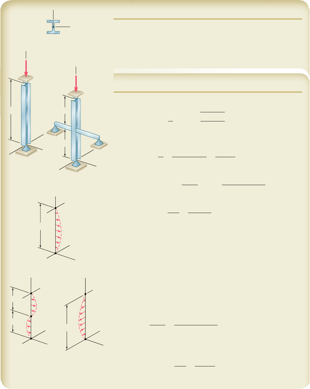
SAMPLE PROBLEM 10.3
Column AB consists of a W10 3 39 rolled-steel shape made of a grade of
steel for which s
Y
5 36 ksi and E 5 29 3 10
6
psi. Determine the allowable
centric load P (a) if the effective length of the column is 24 ft in all direc-
tions, (b) if bracing is provided to prevent the movement of the midpoint
C in the xz plane. (Assume that the movement of point C in the yz plane
is not affected by the bracing.)
SOLUTION
We first compute the value of the slenderness ratio from Eq. 10.41 corre-
sponding to the given yield strength s
Y
5 36 ksi.
L
r
5 4.71
B
29 3 10
6
36 3 10
3
5 133.7
a. Effective Length 5 24 ft. Since r
y
, r
x
, buckling will take place in
the xz plane. For L 5 24 ft and r 5 r
y
5 1.98 in., the slenderness ratio is
L
r
y
5
124 3 122 in
.
1.98 in.
5
288 in
.
1.98 in.
5 145.5
Since Lyr . 133.7, we use Eq. (10.39) in Eq. (10.40) to determine s
cr
s
cr
5 0.877 s
e
5 0.877
p
2
E
1L
y
r2
2
5 0.877
p
2
129 3 10
3
ksi2
1145.52
2
5 11.86 ksi
The allowable stress, determined using Eq. (10.42), and P
all
are
s
all
5
s
cr
1
.
67
5
11.86 ksi
1
.
67
5 7.10 ksi
P
all
5 s
all
A 5 17.10 ksi2111.5 in
2
25 81.7 kips
>
b. Bracing at Midpoint C. Since bracing prevents movement of point
C in the xz plane but not in the yz plane, we must compute the slenderness
ratio correspoinding to buckling in each plane and determine which is larger.
xz Plane: Effective length 5 12 ft 5 144 in., r 5 r
y
5 1.98 in.
Lyr 5 (144 in.)y(1.98 in.) 5 72.7
yz Plane: Effective length 5 24 ft 5 288 in., r 5 r
x
5 4.27 in.
Lyr 5 (288 in.)y(4.27 in.) 5 67.4
Since the larger slenderness ratio corresponds to a smaller allowable load,
we choose Lyr 5 72.7. Since this is smaller than Lyr 5 133.7, we use Eqs.
(10.39) and (10.38) to determine s
cr
s
e
5
p
2
E
1L
y
r2
2
5
p
2
129 3 10
3
ksi2
172.72
2
5 54.1 ksi
s
cr
5
3
0.658
1s
Y
y
s
e
2
4
F
Y
5
3
0.658
136 ksi
y
54.1 ksi2
4
36 ksi 5 27.3 ksi
We now calculate the allowable stress using Eq. (10.42) and the allowable
load.
s
all
5
s
cr
1
.
67
5
27.3 ksi
1
.
67
5 16.32 ksi
P
all
5 s
all
A 5 116.32 ksi2111.5 in
2
2 P
all
5 187.7 ksi >
y
x
W10 39
A 11.5 in
2
r
x
4.27 in.
r
y
1.98 in.
y
B
24 ft
z
x
A
y
B
24 ft
z
x
A
y
B
12 ft
12 ft
z
x
A
C
Buckling in xz plane Buckling in yz plane
y
A
B
24 ft
z
P
x
(a)
y
A
C
B
12 ft
12 ft
z
x
(b)
P
668
bee80288_ch10_630-691.indd Page 668 11/1/10 2:37:28 PM user-f499bee80288_ch10_630-691.indd Page 668 11/1/10 2:37:28 PM user-f499/Users/user-f499/Desktop/Temp Work/Don't Delete Job/MHDQ251:Beer:201/ch10/Users/user-f499/Desktop/Temp Work/Don't Delete Job/MHDQ251:Beer:201/ch
Apago PDF Enhancer
669
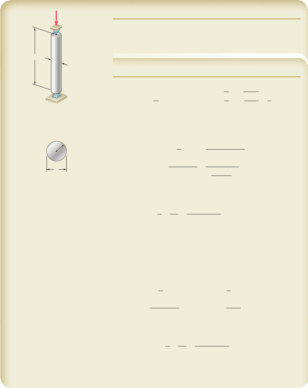
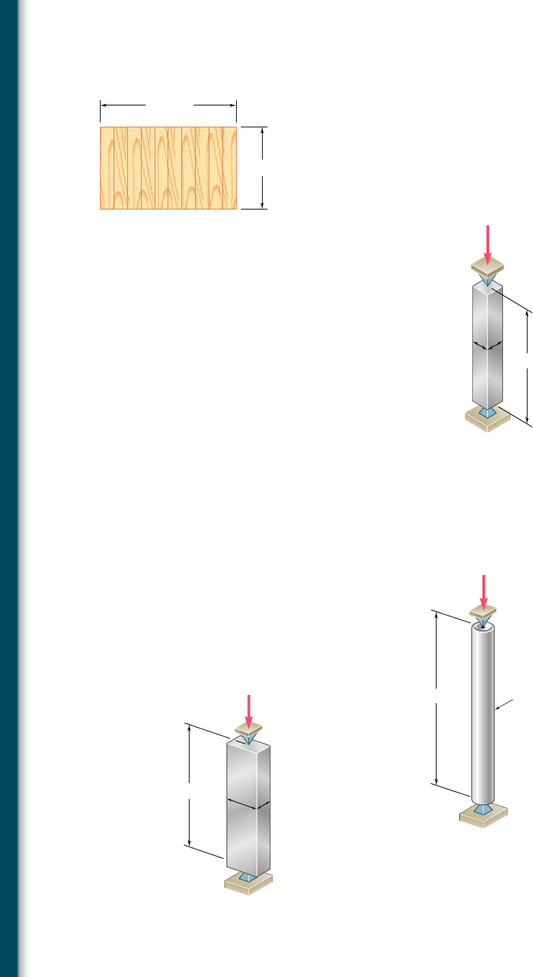
SAMPLE PROBLEM 10.4
Using the aluminum alloy 2014-T6, determine the smallest diameter rod
that can be used to support the centric load P 5 60 kN if (a) L 5 750 mm,
(b) L 5 300 mm.
SOLUTION
For the cross section of a solid circular rod, we have
I 5
p
4
c
4
A 5 pc
2
r 5
B
I
A
5
B
pc
4
y
4
p
c
2
5
c
2
a. Length of 750 mm. Since the diameter of the rod is not known, a
value of Lyr must be assumed; we assume that Lyr . 55 and use Eq. (10.46).
For the centric load P, we have s 5 P/A and write
P
A
5 s
all
5
382 3 10
3
MPa
1
L
y
r
2
2
60 3 10
3
N
pc
2
5
382 3 10
9
Pa
a
0.750
m
c
y
2
b
2
c
4
5 112
.
5 3 10
2
9
m
4
c
5 18
.
31 mm
For c 5 18.44 mm, the slenderness ratio is
L
r
5
L
c
y
2
5
750 mm
1
18.31 mm
2
y
2
5 81.9 . 55
Our assumption is correct, and for L 5 750 mm, the required diameter is
d 5 2c 5 2
1
18.31 mm
2
d
5 36
.
6 mm>
b. Length of 300 mm. We again assume that Lyr . 55. Using
Eq. (10.46), and following the procedure used in part a, we find that c 5
11.58 mm and Lyr 5 51.8. Since Lyr is less than 55, our assumption is wrong; we
now assume that Lyr , 55 and use Eq. (10.459) for the design of this rod.
P
A
5 s
all
5
c
213 2 1.577
a
L
r
bd
MPa
60 3 10
3
N
pc
2
5 c213 2 1.577 a
0.3 m
c
y
2
bd 10
6
Pa
c
5 11
.
95 mm
For c 5 11.95 mm, the slenderness ratio is
L
r
5
L
c
y
2
5
300
mm
1
11.95 mm
2
y
2
5 50.2
Our second assumption that Lyr , 55 is correct. For L 5 300 mm, the
required diameter is
d 5 2c 5 2
1
11.95 mm
2
d
5 23
.
9 mm>
d
c
A
d
B
L
P ⫽ 60 kN
bee80288_ch10_630-691.indd Page 669 11/1/10 9:01:21 PM user-f499bee80288_ch10_630-691.indd Page 669 11/1/10 9:01:21 PM user-f499 /Users/user-f499/Desktop/Temp Work/Don't Delete Job/MHDQ251:Beer:201/ch10/Users/user-f499/Desktop/Temp Work/Don't Delete Job/MHDQ251:Beer:201/ch10
Apago PDF Enhancer
PROBLEMS
670
10.57 Using allowable stress design, determine the allowable centric load
for a column of 6-m effective length that is made from the follow-
ing rolled-steel shape: (a) W200 3 35.9, (b) W200 3 86. Use
s
Y
5 250 MPa and E 5 200 GPa.
10.58 A W8 3 31 rolled-steel shape is used for a column of 21-ft effec-
tive length. Using allowable stress design, determine the allowable
centric load if the yield strength of the grade of steel used is
(a) s
Y
5 36 ksi, (b) s
Y
5 50 ksi. Use E 5 29 3 10
6
psi.
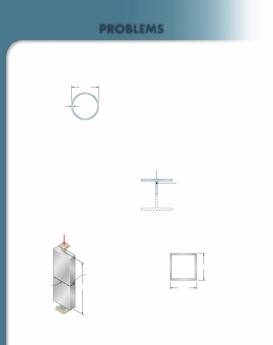
10.59 A steel pipe having the cross section shown is used as a column.
Using the allowable stress design determine the allowable centric
load if the effective length of the column is (a) 18 ft,
(b) 26 ft. Use s
Y
5 36 ksi and E 5 29 3 10
6
psi.
10.6 0 A column is made from half of a W360 3 216 rolled-steel shape,
with the geometric properties as shown. Using allowable stress
design, determine the allowable centric load if the effective length
of the column is (a) 4.0 m, (b) 6.5 m. Use s
Y
5 345 MPa and
E
5 200 GPa.
t
⫽ 0.28 in.
6.0 in.
Fig. P10.59
y
C
x
A ⫽ 13.75 ⫻ 10
3
mm
2
I
x
⫽ 26.0 ⫻ 10
6
mm
4
I
y
⫽ 141.0 ⫻ 10
6
mm
4
Fig. P10.60
10.61 A compression member has the cross section shown and an effec-
tive length of 5 ft. Knowing that the aluminum alloy used is 2014-
T6, determine the allowable centric load.
4.0 in.
4.0 in.
t
⫽ 0.375 in.
Fig. P10.61
A
B
50 mm
20 mm
L
P
Fig. P10.62
10.62 Using the aluminum alloy 2014-T6, determine the largest allowable
length of the aluminum bar AB for a centric load P of magnitude
(a) 150 kN, (b) 90 kN, (c) 25 kN.
bee80288_ch10_630-691.indd Page 670 11/1/10 9:01:27 PM user-f499bee80288_ch10_630-691.indd Page 670 11/1/10 9:01:27 PM user-f499 /Users/user-f499/Desktop/Temp Work/Don't Delete Job/MHDQ251:Beer:201/ch10/Users/user-f499/Desktop/Temp Work/Don't Delete Job/MHDQ251:Beer:201/ch10
Apago PDF Enhancer
671
Problems
10.63 A sawn lumber column with a 7.5 3 5.5-in. cross section has an
18-ft effective length. Knowing that for the grade of wood used the
adjusted allowable stress for compression parallel to the grain is
s
C
5 1200 psi and that the adjusted modulus E 5 470 3 10
3
psi,
determine the maximum allowable centric load for the column.
10. 64 A column having a 3.5-m effective length is made of sawn lumber
with a 114 3 140-mm cross section. Knowing that for the grade of
wood used the adjusted allowable stress for compression parallel to
the grain is s
C
5 7.6 MPa and the adjusted modulus E 5 2.8 GPa,
determine the maximum allowable centric load for the column.
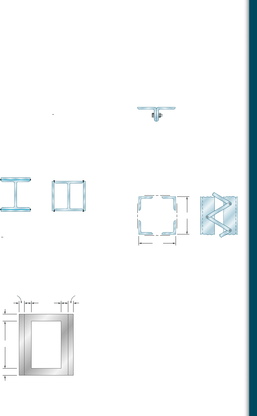
10.65 A compression member of 8.2-ft effective length is obtained by
bolting together two L5 3 3 3
1
2
-in. steel angles as shown. Using
allowable stress design, determine the allowable centric load for
the column. Use s
Y
5 36 ksi and E 5 29 3 10
6
psi.
10.66 and 10.67 A compression member of 9-m effective length is
obtained by welding two 10-mm-thick steel plates to a W250 3 80
rolled-steel shape as shown. Knowing that s
Y
5 345 MPa and
E
5 200 GPa and using allowable stress design, determine the
allowable centric load for the compression member.
Fig. P10.65
Fig. P10.67Fig. P10.66
10.68 A column of 18-ft effective length is obtained by connecting four
L3 3 3 3
3
8
-in. steel angles with lacing bars as shown. Using allow-
able stress design, determine the allowable centric load for the
column. Use s
Y
5 36 ksi and E 5 29 3 10
6
psi.
10.69 An aluminum structural tube is reinforced by bolting two plates to
it as shown for use as a column of 1.7-m effective length. Knowing
that all material is aluminum alloy 2014-T6, determine the maxi-
mum allowable centric load.
8 in.
8 in.
Fig. P10.68
54 mm
8 mm
6 mm 6 mm
34 mm
8 mm 8 mm
8 mm
Fig. P10.69
bee80288_ch10_630-691.indd Page 671 11/1/10 2:37:51 PM user-f499bee80288_ch10_630-691.indd Page 671 11/1/10 2:37:51 PM user-f499/Users/user-f499/Desktop/Temp Work/Don't Delete Job/MHDQ251:Beer:201/ch10/Users/user-f499/Desktop/Temp Work/Don't Delete Job/MHDQ251:Beer:201/ch
Apago PDF Enhancer
672
Columns
10.70 A rectangular column with a 4.4-m effective length is made of
glued laminated wood. Knowing that for the grade of wood used
the adjusted allowable stress for compression parallel to the grain
is s
C
5 8.3 MPa and the adjusted modulus E 5 4.6 GPa, deter-
mine the maximum allowable centric load for the column.
10.71 For a rod made of the aluminum alloy 2014-T6, select the smallest
square cross section that may be used if the rod is to carry a 55-kip
centric load.
216 mm
140 mm
Fig. P10.70
10.72 An aluminum tube of 90-mm outer diameter is to carry a centric
load of 120 kN. Knowing that the stock of tubes available for use
are made of alloy 2014-T6 and with wall thicknesses in increments
of 3 mm from 6 mm to 15 mm, determine the lightest tube that
can be used.
A
B
20 in.
d
d
P 55 kips
Fig. P10.71
A
B
2.25 m
90-mm outside
diameter
120 kN
Fig. P10.72
10.73 A 72-kN centric load must be supported by an aluminum column
as shown. Using the aluminum alloy 6061-T6, determine the mini-
mum dimension b that can be used.
A
B
2b
b
0.45 m
P
Fig. P10.73
bee80288_ch10_630-691.indd Page 672 11/1/10 2:38:01 PM user-f499bee80288_ch10_630-691.indd Page 672 11/1/10 2:38:01 PM user-f499/Users/user-f499/Desktop/Temp Work/Don't Delete Job/MHDQ251:Beer:201/ch10/Users/user-f499/Desktop/Temp Work/Don't Delete Job/MHDQ251:Beer:201/ch
Apago PDF Enhancer
673
Problems
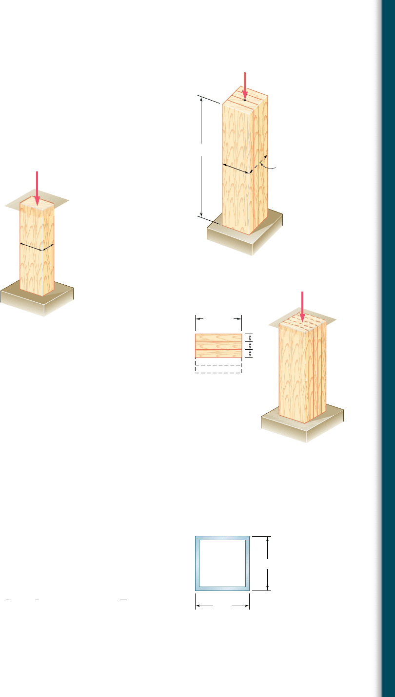
10.74 The glued laminated column shown is free at its top A and fixed
at its base B. Using wood that has an adjusted allowable stress for
compression parallel to the grain s
C
5 9.2 MPa and an adjusted
modulus of elasticity E
5 5.7 GPa, determine the smallest cross
section that can support a centric load of 62 kN.
10.75 An 18-kip centric load is applied to a rectangular sawn lumber col-
umn of 22-ft effective length. Using sawn lumber for which the
adjusted allowable stress for compression parallel to the grain is s
C
5
1050 psi and the adjusted modulus is E
5 440 3 10
3
psi, determine
the smallest cross section that can be used. Use b
5 2d.
2 m
A
B
d
d
P
Fig. P10.74
b
d
P
Fig. P10.75
10.76 A glue laminated column of 3-m effective length is to be made
from boards of 24 3 100-mm cross section. Knowing that for the
grade of wood used, E
5 11 GPa and the adjusted allowable stress
for compression parallel to the grain is s
C
5 9 MPa, determine
the number of boards that must be used to support the centric
load shown when (a) P
5 34 kN, (b) P 5 17 kN.
10.77 A column of 4.5-m effective length must carry a centric load of
900 kN. Knowing that s
Y
5 345 MPa and E 5 200 GPa, use
allowable stress design to select the wide-flange shape of 250-mm
nominal depth that should be used.
10.78 A column of 4.6-m effective length must carry a centric load of
525 kN. Knowing that s
Y
5 345 MPa and E 5 200 GPa, use
allowable stress design to select the wide-flange shape of 200-mm
nominal depth that should be used.
10.79 A column of 22.5-ft effective length must carry a centric load of
288 kips. Using allowable stress design, select the wide-flange
shape of 14-in. nominal depth that should be used. Use s
Y
5 50 ksi
and E
5 29 3 10
6
psi.
10.80 A square steel tube having the cross section shown is used as a
column of 26-ft effective length to carry a centric load of 65 kips.
Knowing that the tubes available for use are made with wall thick-
nesses ranging from
1
4
in. to
3
4
in. in increments of
1
16
in., use allow-
able stress design to determine the lightest tube that can be used.
Use s
Y
5 36 ksi and E 5 29 3 10
6
psi.
10.81 Solve Prob. 10.80, assuming that the effective length of the column
is decreased to 20 ft.
A
B
100 mm
24 mm
24 mm
24 mm
P
Fig. P10.76
6 in.
6 in.
Fig. P10.80
bee80288_ch10_630-691.indd Page 673 11/1/10 2:38:10 PM user-f499bee80288_ch10_630-691.indd Page 673 11/1/10 2:38:10 PM user-f499/Users/user-f499/Desktop/Temp Work/Don't Delete Job/MHDQ251:Beer:201/ch10/Users/user-f499/Desktop/Temp Work/Don't Delete Job/MHDQ251:Beer:201/ch
Apago PDF Enhancer
674
Columns
10.82 A centric load P must be supported by the steel bar AB. Using allow-
able stress design, determine the smallest dimension d of the cross
section that can be used when (a) P
5 108 kN, (b) P 5 166 kN. Use
s
Y
5 250 MPa and E 5 200 GPa.
10.83 Two 3
1
2
3 2
1
2
-in. angles are bolted together as shown for use as a
column of 6-ft effective length to carry a centric load of 54 kips.
Knowing that the angles available have thicknesses of
1
4
,
3
8
, and
1
2
in.,
use allowable stress design to determine the lightest angles that can
be used. Use s
Y
5 36 ksi and E 5 29 3 10
6
psi.
A
B
3 d
1.4 m
d
P
Fig. P10.82
2
in.
1
2
2
in.
1
2
3
in.
1
2
Fig. P10.83
10.84 Two 89 3 64-mm angles are bolted together as shown for use as a
column of 2.4-m effective length to carry a centric load of 180 kN.
Knowing that the angles available have thicknesses of 6.4 mm, 9.5 mm,
and 12.7 mm, use allowable stress design to determine the lightest
angles that can be used. Use s
Y
5 250 MPa and E 5 200 GPa.
*10.85 A column with a 5.8-m effective length supports a centric load,
with ratio of dead to live load equal to 1.35. The dead load factor
is g
D
5 1.2, the live load factor g
L
5 1.6, and the resistance factor
f
5 0.90. Use load and resistance factor design to determine the
allowable centric dead and live loads if the column is made of the
following rolled-steel shape: (a) W250 3 67, (b) W360 3 101. Use
s
Y
5 345 MPa and E 5 200 GPa.
*10.86 A rectangular steel tube having the cross section shown is used as
a column of 14.5-ft effective length. Knowing that s
Y
5 36 ksi and
E
5 29 3 10
6
psi., use load and resistance factor design to deter-
mine the largest centric live load that can be applied if the centric
dead load is 54 kips. Use a dead load factor g
D
5 1.2, a live load
factor g
L
5 1.6 and the resistance factor f 5 0.90.
*10.87 A steel column of 5.5-m effective length must carry a centric dead
load of 310 kN and a centric live load of 375 kN. Knowing that
s
Y
5 250 MPa and E 5 200 GPa, use load and resistance factor
design to select the wide-flange shape of 310-mm nominal depth
that should be used. The dead load factor g
D
5 1.2, the live load
factor g
L
5 1.6, and the resistance factor f 5 0.90.
*10.88 The steel tube having the cross section shown is used as a column of
15-ft effective length to carry a centric dead load of 51 kips and a
centric live load of 58 kips. Knowing that the tubes available for use
are made with wall thicknesses in increments of
1
16
in. from
3
16
in. to
3
8
in., use load and resistance factor design to determine the lightest
tube that can be used. Use s
Y
5 36 ksi and E 5 29 3 10
6
psi. The
dead load factor g
D
5 1.2, the live load factor g
L
5 1.6, and the
resistance factor f
5 0.90.
89 mm 89 mm
64 mm
Fig. P10.84
7 in.
5 in.
in.
t
5
16
Fig. P10.86
6 in.
6 in.
Fig. P10.88
bee80288_ch10_630-691.indd Page 674 11/1/10 2:38:19 PM user-f499bee80288_ch10_630-691.indd Page 674 11/1/10 2:38:19 PM user-f499/Users/user-f499/Desktop/Temp Work/Don't Delete Job/MHDQ251:Beer:201/ch10/Users/user-f499/Desktop/Temp Work/Don't Delete Job/MHDQ251:Beer:201/ch
Apago PDF Enhancer
675
10.7 DESIGN OF COLUMNS UNDER AN
ECCENTRIC LOAD
In this section, the design of columns subjected to an eccentric load
will be considered. You will see how the empirical formulas devel-
oped in the preceding section for columns under a centric load can
be modified and used when the load P applied to the column has
an eccentricity e which is known.
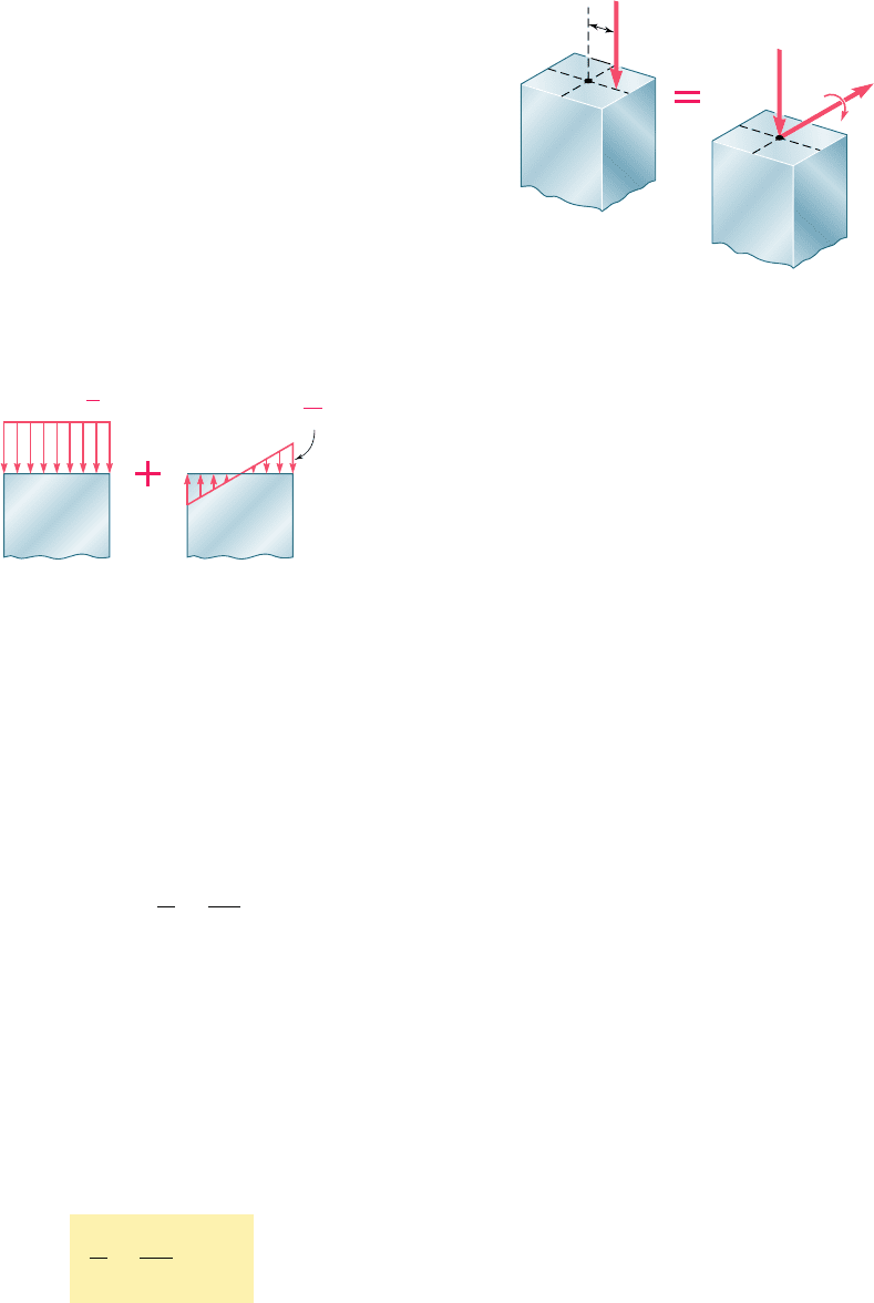
We first recall from Sec. 4.12 that an eccentric axial load P
applied in a plane of symmetry of the column can be replaced by an
equivalent system consisting of a centric load P and a couple M of
moment M 5 Pe, where e is the distance from the line of action of
the load to the longitudinal axis of the column (Fig. 10.32). The
normal stresses exerted on a transverse section of the column can
then be obtained by superposing the stresses due, respectively, to
the centric load P and to the couple M (Fig. 10.33), provided that
10.7 Design of Columns under an
Eccentric Load
P
e
C
M Pe
C
P
Fig. 10.32 Column with eccentric load.
centric
P
A
bending
Mc
I
Fig. 10.33 Stresses on column
transverse section.
the section considered is not too close to either end of the column,
and as long as the stresses involved do not exceed the proportional
limit of the material. The normal stresses due to the eccentric load
P can thus be expressed as
s 5 s
centric
1
s
bendin
g
(10.51)
Recalling the results obtained in Sec. 4.12, we find that the maxi-
mum compressive stress in the column is
s
max
5
P
A
1
M
c
I
(10.52)
In a properly designed column, the maximum stress defined by
Eq. (10.52) should not exceed the allowable stress for the column.
Two alternative approaches can be used to satisfy this requirement,
namely, the allowable-stress method and the interaction method.
a. Allowable-Stress Method. This method is based on the
assumption that the allowable stress for an eccentrically loaded col-
umn is the same as if the column were centrically loaded. We must
have, therefore, s
max
# s
all
, where s
all
is the allowable stress under
a centric load, or substituting for s
max
from Eq. (10.52)
P
A
1
M
c
I
# s
all
(10.53)
bee80288_ch10_630-691.indd Page 675 11/1/10 2:38:30 PM user-f499bee80288_ch10_630-691.indd Page 675 11/1/10 2:38:30 PM user-f499/Users/user-f499/Desktop/Temp Work/Don't Delete Job/MHDQ251:Beer:201/ch10/Users/user-f499/Desktop/Temp Work/Don't Delete Job/MHDQ251:Beer:201/ch
Apago PDF Enhancer
676
Columns
The allowable stress is obtained from the formulas of Sec. 10.6
which, for a given material, express s
all
as a function of the slender-
ness ratio of the column. The major engineering codes require that
the largest value of the slenderness ratio of the column be used to
determine the allowable stress, whether or not this value corresponds
to the actual plane of bending. This requirement sometimes results
in an overly conservative design.
EXAMPLE 10.04
A column with a 2-in.-square cross section and 28-in. effective length is
made of the aluminum alloy 2014-T6. Using the allowable-stress method,
determine the maximum load P that can be safely supported with an
eccentricity of 0.8 in.
We first compute the radius of gyration r using the given data
A
5
1
2 in.
2
2
5 4 in
2
I 5
1
12
1
2 in.
2
4
5 1.333 in
4
r 5
B
I
A
5
B
1.333 in
4
4 in
2
5 0.5774 in.
We next compute Lyr 5 (28 in.)y(0.5774 in.) 5 48.50.
Since Lyr , 55, we use Eq. (10.48) to determine the allowable
stress for the aluminum column subjected to a centric load. We have
s
all
5
3
30.9 2 0.229
1
48.50
24
5 19.79 ksi
We now use Eq. (10.53) with M 5 Pe and c 5
1
2
1
2 in.
2
5 1 in. to
determine the allowable load:
P
4 in
2
1
P
1
0.8 in.
21
1 in.
2
1
.
333 in
4
# 19.79 ksi
P # 23.3
k
ips
The maximum load that can be safely applied is P 5 23.3 kips.
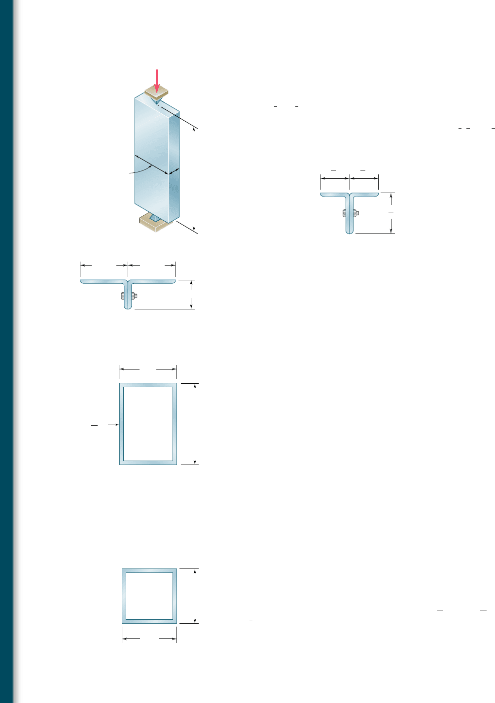
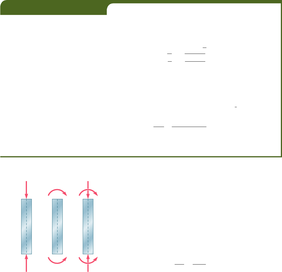
b. Interaction Method. We recall that the allowable stress for a
column subjected to a centric load (Fig. 10.34a) is generally smaller
than the allowable stress for a column in pure bending (Fig. 10.34b),
since the former takes into account the possibility of buckling.
Therefore, when we use the allowable-stress method to design an
eccentrically loaded column and write that the sum of the stresses
due to the centric load P and the bending couple M (Fig. 10.34c)
must not exceed the allowable stress for a centrically loaded column,
the resulting design is generally overly conservative. An improved
method of design can be developed by rewriting Eq. 10.53 in the
form
P
y
A
s
a
ll
1
Mc
y
I
s
a
ll
# 1
(10.54)
and substituting for s
all
in the first and second terms the values
of the allowable stress which correspond, respectively, to the
(a)(c)(b)
M
'
P'P'
M'
PP
M M
Fig. 10.34 Column load possibilities.
bee80288_ch10_630-691.indd Page 676 11/1/10 2:38:35 PM user-f499bee80288_ch10_630-691.indd Page 676 11/1/10 2:38:35 PM user-f499/Users/user-f499/Desktop/Temp Work/Don't Delete Job/MHDQ251:Beer:201/ch10/Users/user-f499/Desktop/Temp Work/Don't Delete Job/MHDQ251:Beer:201/ch