Beer F.P., Johnston E.R., DeWolf J.T., Mazurek D.F. Mechanics of Materials
Подождите немного. Документ загружается.


Apago PDF Enhancer
177
shearing stress allowable in the material will not be exceeded when
the shaft is transmitting the required power at the specified speed.
To determine the torque exerted on the shaft, we recall from
elementary dynamics that the power P associated with the rotation
of a rigid body subjected to a torque T is
P 5 Tv (3.19)
where v is the angular velocity of the body expressed in radians per
second. But v 5 2pf, where f is the frequency of the rotation, i.e., the
number of revolutions per second. The unit of frequency is thus 1 s
21
and is called a hertz (Hz). Substituting for v into Eq. (3.19), we write
P 5 2p fT (3.20)
If SI units are used we verify that, with f expressed in Hz and
T in N ? m, the power will be expressed in N ? m/s, that is, in watts
(W). Solving Eq. (3.20) for T, we obtain the torque exerted on a shaft
transmitting the power P at a frequency of rotation f,
T 5
P
2p f
(3.21)
where P, f, and T are expressed in the units indicated above.
After having determined the torque T that will be applied to
the shaft and having selected the material to be used, the designer
will carry the values of T and of the maximum allowable stress into
the elastic torsion formula (3.9). Solving for Jyc, we have
J
c
5
T
t
m
a
x
(3.22)
and obtain in this way the minimum value allowable for the parameter
Jyc. We check that, if SI units are used, T will be expressed in N ? m,
t
max
in Pa (or N/m
2
), and Jyc will be obtained in m
3
. In the case of a solid
circular shaft,
J
5
1
2
pc
4
, and
J
y
c 5
1
2
pc
3
; substituting this value for
Jyc into Eq. (3.22) and solving for c yields the minimum allowable
value for the radius of the shaft. In the case of a hollow circular shaft,
the critical parameter is Jyc
2
, where c
2
is the outer radius of the shaft;
the value of this parameter may be computed from Eq. (3.11) of Sec.
3.4 to determine whether a given cross section will be acceptable.
When U.S. customary units are used, the frequency is usually
expressed in rpm and the power in horsepower (hp). It is then neces-
sary, before applying formula (3.21), to convert the frequency into
revolutions per second (i.e., hertzes) and the power into ft ? lb/s or
in ? lb/s through the use of the following relations:
1 rpm 5
1
60
s
21
5
1
60
Hz
1 hp 5 550 ft ? lb/s 5 6600 in ? lb/s
If we express the power in in ? lb/s, formula (3.21) will yield the value of
the torque T in lb ? in. Carrying this value of T into Eq. (3.22), and ex-
pressing t
max
in psi, we obtain the value of the parameter Jyc in in
3
.
3.7 Design of Transmission Shafts
bee80288_ch03_140-219.indd Page 177 11/2/10 12:48:17 AM user-f499bee80288_ch03_140-219.indd Page 177 11/2/10 12:48:17 AM user-f499 /Users/user-f499/Desktop/Temp Work/Don't Delete Job/MHDQ251:Beer:201/ch03/Users/user-f499/Desktop/Temp Work/Don't Delete Job/MHDQ251:Beer:201/ch03

Apago PDF Enhancer
EXAMPLE 3.06
What size of shaft should be used for the rotor of a 5-hp motor operating
at 3600 rpm if the shearing stress is not to exceed 8500 psi in the shaft?
We first express the power of the motor in in ? lb/s and its frequency
in cycles per second (or hertzes).
P 5 15 hp2
a
6600 in ? lb/s
1 hp
b
5 33,000 in ? lb/s
f
5 13600 rpm2
1
Hz
60 rpm
5 60 Hz 5 60 s
21
The torque exerted on the shaft is given by Eq. (3.21):
T 5
P
2p f
5
33,000 in ?
lb
/s
2p
1
60 s
21
2
5 87.54 lb ? in.
Substituting for T and t
max
into Eq. (3.22), we write
J
c
5
T
t
max
5
87.54 lb ? in.
8500 psi
5 10.30 3 10
23
in
3
But
J
y
c 5
1
2
pc
3
for a solid shaft. We have, therefore,
1
2
pc
3
5 10.30 3 10
23
in
3
c
5 0
.
18
7
2 in
.
d
5 2
c
5 0
.
374 in
.
A
3
8
-in. shaft should be used.
178
EXAMPLE 3.07
A shaft consisting of a steel tube of 50-mm outer diameter is to transmit
100 kW of power while rotating at a frequency of 20 Hz. Determine the
tube thickness that should be used if the shearing stress is not to exceed
60 MPa.
The torque exerted on the shaft is given by Eq. (3.21):
T 5
P
2p
f
5
100 3 10
3
W
2p 120 Hz2
5 795.8 N ? m
From Eq. (3.22) we conclude that the parameter Jyc
2
must be at least
equal to
J
c
2
5
T
t
m
a
x
5
795.8 N ? m
60 3 10
6
N/m
2
5 13.26 3 10
26
m
3
(3.23)
But, from Eq. (3.10) we have
J
c
2
5
p
2c
2
1c
4
2
2 c
4
1
25
p
0.050
310.0252
4
2 c
4
1
4
(3.24)
Equating the right-hand members of Eqs. (3.23) and (3.24), we obtain:
10.0252
4
2 c
4
1
5
0.050
p
113.26 3 10
26
2
c
4
1
5 390.6 3 10
2
9
2 211.0 3 10
2
9
5 179.6 3 10
2
9
m
4
c
1
5 20.6 3 10
2
3
m 5 20.6 mm
The corresponding tube thickness is
c
2
2 c
1
5 25 mm 2 20.6 mm 5 4.4 mm
A tube thickness of 5 mm should be used.
bee80288_ch03_140-219.indd Page 178 11/2/10 12:48:19 AM user-f499bee80288_ch03_140-219.indd Page 178 11/2/10 12:48:19 AM user-f499 /Users/user-f499/Desktop/Temp Work/Don't Delete Job/MHDQ251:Beer:201/ch03/Users/user-f499/Desktop/Temp Work/Don't Delete Job/MHDQ251:Beer:201/ch03
Apago PDF Enhancer
179
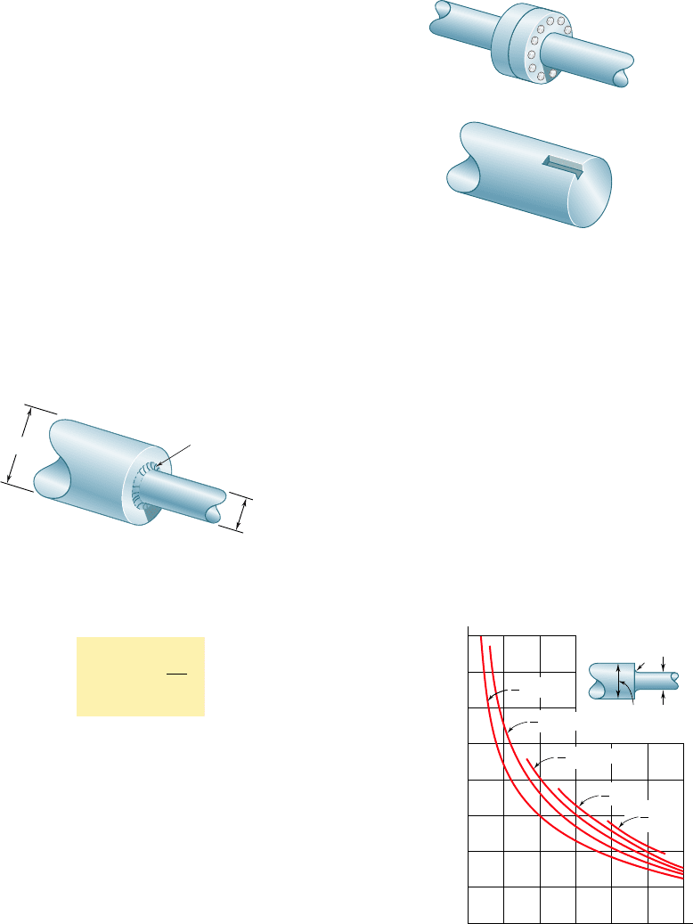
3.8 STRESS CONCENTRATIONS IN CIRCULAR SHAFTS
The torsion formula t
max
5 TcyJ was derived in Sec. 3.4 for a circular
shaft of uniform cross section. Moreover, we had assumed earlier in
Sec. 3.3 that the shaft was loaded at its ends through rigid end plates
solidly attached to it. In practice, however, the torques are usually
applied to the shaft through flange couplings (Fig. 3.27a) or through
gears connected to the shaft by keys fitted into keyways (Fig. 3.27b).
In both cases one should expect the distribution of stresses, in and
near the section where the torques are applied, to be different from
that given by the torsion formula. High concentrations of stresses,
for example, will occur in the neighborhood of the keyway shown in
Fig. 3.27b. The determination of these localized stresses may be
carried out by experimental stress analysis methods or, in some cases,
through the use of the mathematical theory of elasticity.
As we indicated in Sec. 3.4, the torsion formula can also be
used for a shaft of variable circular cross section. In the case of a
shaft with an abrupt change in the diameter of its cross section,
however, stress concentrations will occur near the discontinuity, with
the highest stresses occurring at A (Fig. 3.28). These stresses may
3.8 Stress Concentrations in Circular Shafts
D
d
A
Fig. 3.28 Shaft with change in diameter.
be reduced through the use of a fillet, and the maximum value of
the shearing stress at the fillet can be expressed as
t
max
5 K
T
c
J
(3.25)
where the stress TcyJ is the stress computed for the smaller-diameter
shaft, and where K is a stress-concentration factor. Since the factor
K depends only upon the ratio of the two diameters and the ratio of
the radius of the fillet to the diameter of the smaller shaft, it may
be computed once and for all and recorded in the form of a table
or a graph, as shown in Fig. 3.29. We should note, however, that this
procedure for determining localized shearing stresses is valid only as
long as the value of t
max
given by Eq. (3.25) does not exceed the
proportional limit of the material, since the values of K plotted in
Fig. 3.29 were obtained under the assumption of a linear relation
between shearing stress and shearing strain. If plastic deformations
occur, they will result in values of the maximum stress lower than
those indicated by Eq. (3.25).
†W. D. Pilkey, Peterson’s Stress Concentration Factors, 2nd ed., John Wiley & Sons, New
York, 1997.
(a)
(b)
Fig. 3.27 Shaft examples.
1.8
1.7
1.6
1.5
K
D
r
1.4
1.3
1.2
1.1
1.0
0 0.05 0.10 0.200.15 0.25 0.30
r/d
D
d
1.111
D
d
1.25
D
d
1.666
D
d
2
D
d
2.5
d
Fig. 3.29 Stress-concentration factors
for fillets in circular shafts.†
bee80288_ch03_140-219.indd Page 179 9/21/10 3:07:09 PM user-f499bee80288_ch03_140-219.indd Page 179 9/21/10 3:07:09 PM user-f499 /Users/user-f499/Desktop/Temp Work/Don't Delete Job/MHDQ251:Beer:201/ch03/Users/user-f499/Desktop/Temp Work/Don't Delete Job/MHDQ251:Beer:201/ch03
Apago PDF Enhancer
180
SAMPLE PROBLEM 3.6
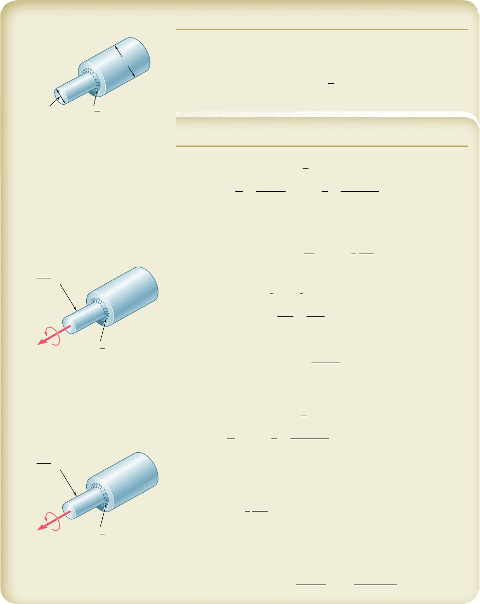
The stepped shaft shown is to rotate at 900 rpm as it transmits power from a
turbine to a generator. The grade of steel specified in the design has an allow-
able shearing stress of 8 ksi. (a) For the preliminary design shown, determine
the maximum power that can be transmitted. (b) If in the final design the
radius of the fillet is increased so that r 5
15
16
in., what will be the percent change,
relative to the preliminary design, in the power that can be transmitted?
SOLUTION
a. Preliminary Design. Using the notation of Fig. 3.32, we have:
D 5 7.50 in., d 5 3.75 in., r 5
9
16
in. 5 0.5625 in.
D
d
5
7.50 in.
3
.
75 in
.
5 2
r
d
5
0.5625 in.
3
.
75 in
.
5 0.15
A stress-concentration factor K 5 1.33 is found from Fig. 3.29.
Torque. Recalling Eq. (3.25), we write
t
max
5 K
Tc
J
T 5
J
c
t
max
K
(1)
where Jyc refers to the smaller-diameter shaft:
J
y
c 5
1
2
pc
3
5
1
2
p11.875 in.2
3
5 10.35 in
3
and where
t
max
K
5
8
k
si
1
.
33
5 6.02 ksi
Substituting into Eq. (1), we find T 5 (10.35 in
3
)(6.02 ksi) 5 62.3 kip ? in.
Power. Since
f
5 1900 rpm2
1
Hz
60 rpm
5 15 Hz 5 15 s
21
,
we write
P
a
5 2p fT 5 2p(15 s
21
)(62.3 kip ? in.) 5 5.87 3 10
6
in. ? lb/s
P
a
5 (5.87 3 10
6
in. ? lb/s)(1 hp/6600 in. ? lb/s) P
a
5 890 hp
◀
b. Final Design. For r 5
15
16
in. 5 0.9375 in.,
D
d
5 2
r
d
5
0.9375 in.
3
.
75 in
.
5 0.250
K
5
1.20
Following the procedure used above, we write
t
max
K
5
8
k
si
1
.
20
5 6.67 ksi
T 5
J
c
t
max
K
5 110.35 in
3
216.67 ksi25 69.0 kip ? in.
P
b
5 2p f T 5 2p115 s
2
1
2169.0 kip ? in.25 6.50 3 10
6
in. ? lb/s
P
b
5 16.50 3 10
6
in. ? lb/s211 hp/6600 in. ? lb/s25 985 hp
Percent Change in Power
Percent change 5 100
P
b
2 P
a
P
a
5 100
985 2 890
890
5111%
◀
3.75 in.
9
16
r
⫽
in.
7.50 in.
K
6.02 ksi
9
16
r in.
⫽
T
a
62.3 kip · in.
⫽
⫽⫽
max
m
K
6.67 ksi
15
16
r in.
⫽
T
b
69.0 kip · in.
⫽
⫽⫽
max
m
bee80288_ch03_140-219.indd Page 180 11/2/10 1:37:52 AM user-f499bee80288_ch03_140-219.indd Page 180 11/2/10 1:37:52 AM user-f499 /Users/user-f499/Desktop/Temp Work/Don't Delete Job/MHDQ251:Beer:201/ch03/Users/user-f499/Desktop/Temp Work/Don't Delete Job/MHDQ251:Beer:201/ch03
Apago PDF Enhancer
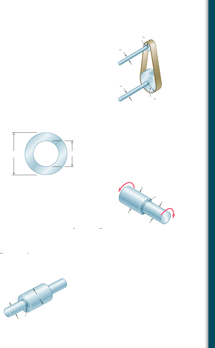
PROBLEMS
181
3.64 Determine the maximum shearing stress in a solid shaft of
12-mm diameter as it transmits 2.5 kW at a frequency of (a) 25 Hz,
(b) 50 Hz.
3.65 Determine the maximum shearing stress in a solid shaft of
1.5-in. diameter as it transmits 75 hp at a speed of (a) 750 rpm,
(b) 1500 rpm.
3.66 Design a solid steel shaft to transmit 0.375 kW at a frequency of
29 Hz, if the shearing stress in the shaft is not to exceed 35 MPa.
3.67 Design a solid steel shaft to transmit 100 hp at a speed of 1200 rpm,
if the maximum shearing stress is not to exceed 7500 psi.
3.68 Determine the required thickness of the 50-mm tubular shaft of
Example 3.07, if it is to transmit the same power while rotating at
a frequency of 30 Hz.
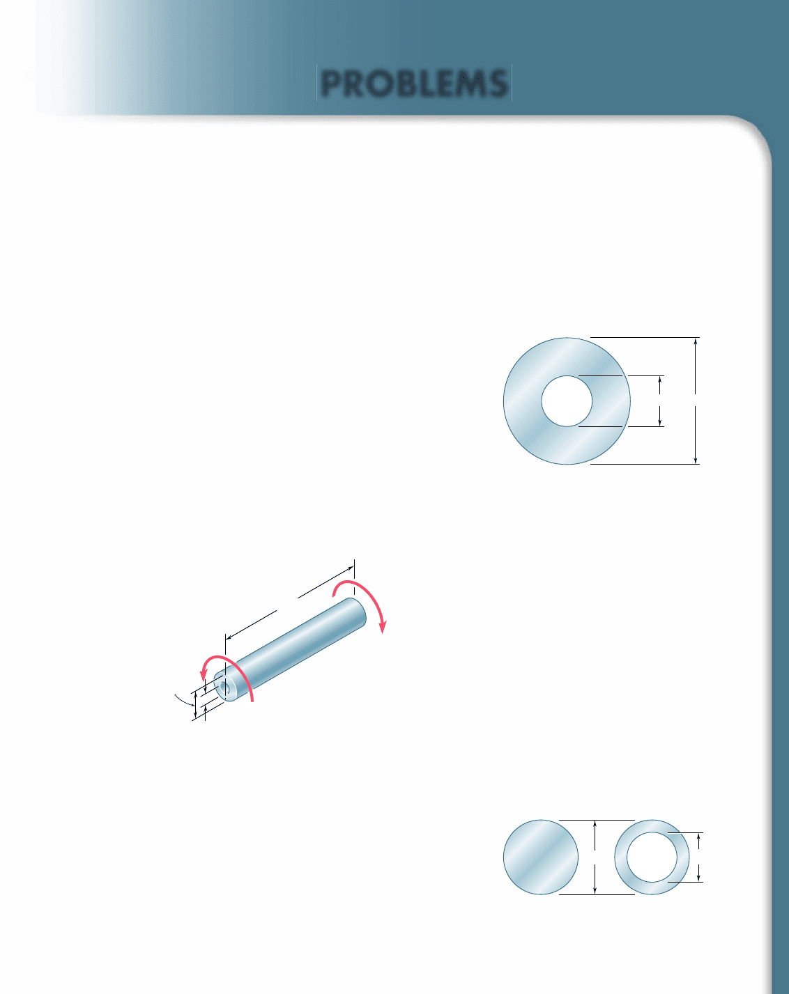
3.69 While a steel shaft of the cross section shown rotates at 120 rpm,
a stroboscopic measurement indicates that the angle of twist is 28
in a 12-ft length. Using G 5 11.2 3 10
6
psi, determine the power
being transmitted.
3.70 The hollow steel shaft shown (G 5 77.2 GPa, t
all
5 50 MPa)
rotates at 240 rpm. Determine (a) the maximum power that can
be transmitted, (b) the corresponding angle of twist of the shaft.
3 in.1.2 in.
Fig. P3.69
5 m
60 mm
25 mm
T
T
'
Fig. P3.70 and P3.71
d
2
40 mm
(a)(b)
Fig. P3.72
3.71 As the hollow steel shaft shown rotates at 180 rpm, a stroboscopic
measurement indicates that the angle of twist of the shaft is 38.
Knowing that G 5 77.2 GPa, determine (a) the power being trans-
mitted, (b) the maximum shearing stress in the shaft.
3.72 The design of a machine element calls for a 40-mm-outer-diameter
shaft to transmit 45 kW. (a) If the speed of rotation is 720 rpm,
determine the maximum shearing stress in shaft a. (b) If the speed
of rotation can be increased 50% to 1080 rpm, determine the larg-
est inner diameter of shaft b for which the maximum shearing
stress will be the same in each shaft.
bee80288_ch03_140-219.indd Page 181 9/21/10 3:07:25 PM user-f499bee80288_ch03_140-219.indd Page 181 9/21/10 3:07:25 PM user-f499 /Users/user-f499/Desktop/Temp Work/Don't Delete Job/MHDQ251:Beer:201/ch03/Users/user-f499/Desktop/Temp Work/Don't Delete Job/MHDQ251:Beer:201/ch03
Apago PDF Enhancer
182
Torsion
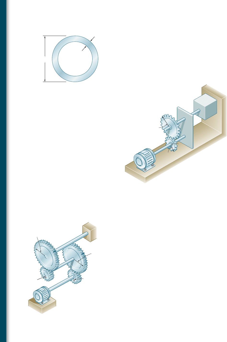
3.73 A steel pipe of 3.5-in. outer diameter is to be used to transmit a
torque of 3000 lb ? ft without exceeding an allowable shearing
stress of 8 ksi. A series of 3.5-in.-outer-diameter pipes is available
for use. Knowing that the wall thickness of the available pipes var-
ies from 0.25 in. to 0.50 in. in 0.0625-in. increments, choose the
lightest pipe that can be used.
3.74 The two solid shafts and gears shown are used to transmit 16 hp from
the motor at A operating at a speed of 1260 rpm to a machine tool
at D. Knowing that the maximum allowable shearing stress is 8 ksi,
determine the required diameter (a) of shaft AB, (b) of shaft CD.
3.5 in.
t
Fig. P3.73
C
5 in.
3 in.
D
A
B
Fig. P3.74 and P3.75
3.75 The two solid shafts and gears shown are used to transmit 16 hp
from the motor at A operating at a speed of 1260 rpm to a machine
tool at D. Knowing that each shaft has a diameter of 1 in., determine
the maximum shearing stress (a) in shaft AB, (b) in shaft CD.
3.76 Three shafts and four gears are used to form a gear train that will
transmit 7.5 kW from the motor at A to a machine tool at F. (Bear-
ings for the shafts are omitted in the sketch.) Knowing that the fre-
quency of the motor is 30 Hz and that the allowable stress for each
shaft is 60 MPa, determine the required diameter of each shaft.
3.77 Three shafts and four gears are used to form a gear train that will
transmit power from the motor at A to a machine tool at F. (Bear-
ings for the shafts are omitted in the sketch.) The diameter of each
shaft is as follows: d
AB
5 16 mm, d
CD
5 20 mm, d
EF
5 28 mm.
Knowing that the frequency of the motor is 24 Hz and that the
allowable shearing stress for each shaft is 75 MPa, determine the
maximum power that can be transmitted.
3.78 A 1.5-m-long solid steel shaft of 48-mm diameter is to transmit
36 kW between a motor and a machine tool. Determine the lowest
speed at which the shaft can rotate, knowing that G 5 77.2 GPa,
that the maximum shearing stress must not exceed 60 MPa, and
the angle of twist must not exceed 2.58.
C
150 mm
60 mm
B
A
F
60 mm
D
150 mm
E
Fig. P3.76 and P3.77
bee80288_ch03_140-219.indd Page 182 9/21/10 3:07:32 PM user-f499bee80288_ch03_140-219.indd Page 182 9/21/10 3:07:32 PM user-f499 /Users/user-f499/Desktop/Temp Work/Don't Delete Job/MHDQ251:Beer:201/ch03/Users/user-f499/Desktop/Temp Work/Don't Delete Job/MHDQ251:Beer:201/ch03
Apago PDF Enhancer
183
Problems
3.79 A 2.5-m-long steel shaft of 30-mm diameter rotates at a frequency
of 30 Hz. Determine the maximum power that the shaft can trans-
mit, knowing that G 5 77.2 GPa, that the allowable shearing stress
is 50 MPa, and that the angle of twist must not exceed 7.58.
3.80 A steel shaft must transmit 210 hp at a speed of 360 rpm. Knowing
that G 5 11.2 3 10
6
psi, design a solid shaft so that the maximum
shearing stress will not exceed 12 ksi and the angle of twist in an
8.2-ft length will not exceed 38.
3.81 The shaft-disk-belt arrangement shown is used to transmit 3 hp
from point A to point D. (a) Using an allowable shearing stress of
9500 psi, determine the required speed of shaft AB. (b) Solve part
a, assuming that the diameters of shafts AB and CD are, respec-
tively, 0.75 in. and 0.625 in.
3.82 A 1.6-m-long tubular steel shaft of 42-mm outer diameter d
1
is to
be made of a steel for which t
all
5 75 MPa and G 5 77.2 GPa.
Knowing that the angle of twist must not exceed 48 when the shaft
is subjected to a torque of 900 N ? m, determine the largest inner
diameter d
2
that can be specified in the design.
B
C
D
A
3
4
in.
5
8
in.
1
2
r
4 in.
1
8
r 1 in.
Fig. P3.81
d
1
42 mm
d
2
Fig. P3.82 and P3.83
2 in.
1.5 in.
r
T
T'
Fig. P3.84 and P3.85
90 mm
45 mm
r
Fig. P3.86
3.83 A 1.6-m-long tubular steel shaft (G 5 77.2 GPa) of 42-mm outer
diameter d
1
and 30-mm inner diameter d
2
is to transmit 120 kW
between a turbine and a generator. Knowing that the allowable shear-
ing stress is 65 MPa and that the angle of twist must not exceed 38,
determine the minimum frequency at which the shaft can rotate.
3.84 Knowing that the stepped shaft shown transmits a torque of magni-
tude T 5 2.50 kip ? in., determine the maximum shearing stress in
the shaft when the radius of the fillet is (a) r 5
1
8
in., (b) r 5
3
16
in.
3.85 Knowing that the allowable shearing stress is 8 ksi for the stepped
shaft shown, determine the magnitude T of the largest torque
that can be transmitted by the shaft when the radius of the fillet
is (a) r 5
3
16
in., (b) r 5
1
4
in.
3.86 The stepped shaft shown must transmit 40 kW at a speed of 720 rpm.
Determine the minimum radius r of the fillet if an allowable stress
of 36 MPa is not to be exceeded.
bee80288_ch03_140-219.indd Page 183 9/21/10 3:07:39 PM user-f499bee80288_ch03_140-219.indd Page 183 9/21/10 3:07:39 PM user-f499 /Users/user-f499/Desktop/Temp Work/Don't Delete Job/MHDQ251:Beer:201/ch03/Users/user-f499/Desktop/Temp Work/Don't Delete Job/MHDQ251:Beer:201/ch03
Apago PDF Enhancer
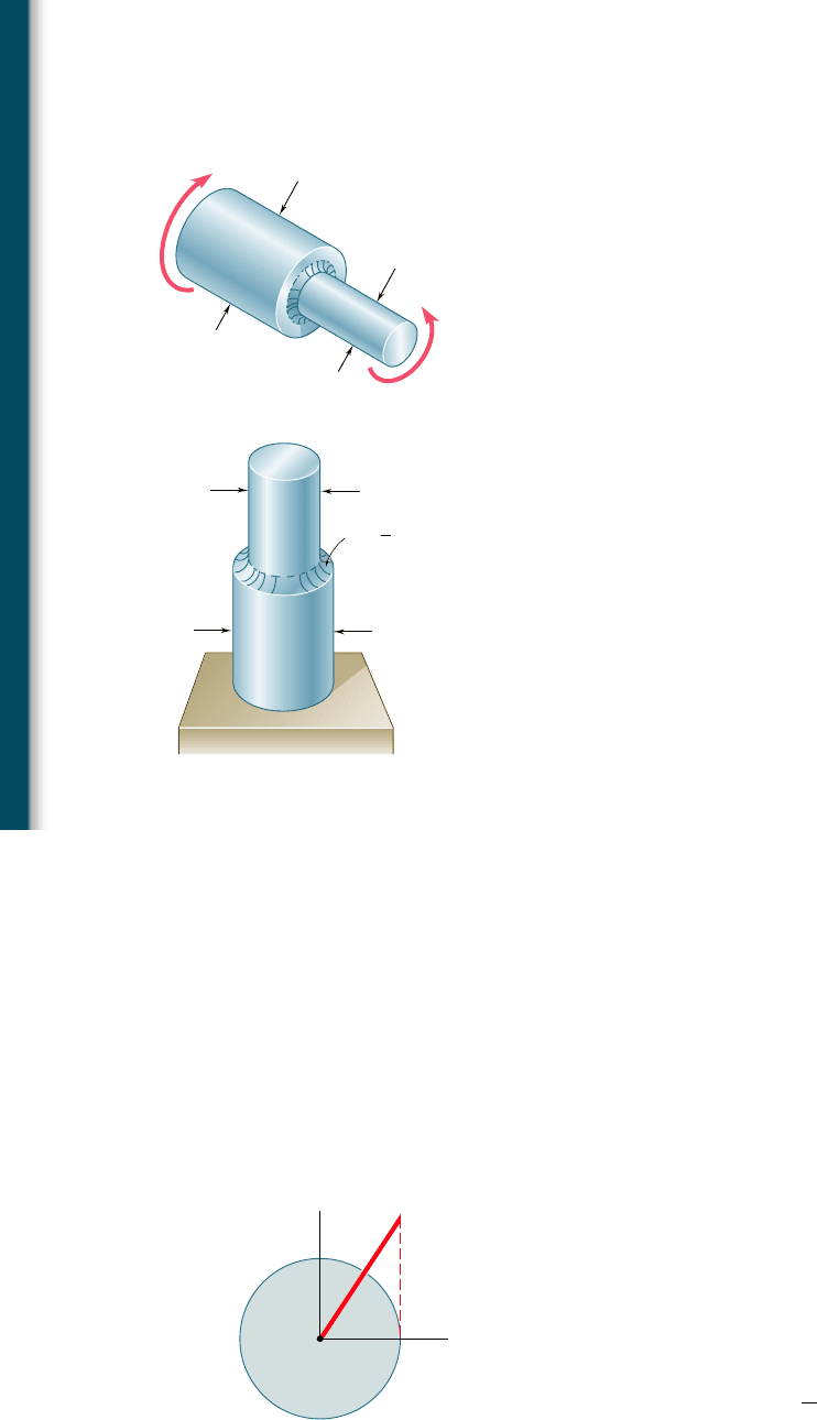
3.87 The stepped shaft shown must transmit 45 kW. Knowing that the
allowable shearing stress in the shaft is 40 MPa and that the radius
of the fillet is r 5 6 mm, determine the smallest permissible speed
of the shaft.
3.88 The stepped shaft shown must rotate at a frequency of 50 Hz.
Knowing that the radius of the fillet is r 5 8 mm and the allowable
shearing stress is 45 MPa, determine the maximum power that can
be transmitted.
3.89 In the stepped shaft shown, which has a full quarter-circular fil-
let, D 5 1.25 in. and d 5 1 in. Knowing that the speed of the
shaft is 2400 rpm and that the allowable shearing stress is 7500 psi,
determine the maximum power that can be transmitted by the
shaft.
3.90 A torque of magnitude T 5 200 lb ? in. is applied to the stepped
shaft shown, which has a full quarter-circular fillet. Knowing that
D 5 1 in., determine the maximum shearing stress in the shaft
when (a) d 5 0.8 in., (b) d 5 0.9 in.
3.91 In the stepped shaft shown, which has a full quarter-circular fillet,
the allowable shearing stress is 80 MPa. Knowing that D 5 30 mm,
determine the largest allowable torque that can be applied to the
shaft if (a) d 5 26 mm, (b) d 5 24 mm.
60 mm
30 mm
T
T'
Fig. P3.87 and P3.88
r
⫽
⫺
D
(Dd)
1
2
d
Full quarter-circular fillet
extends to ed
g
e of lar
g
er shaft.
Fig. P3.89, P3.90, and P3.91
*3.9 PLASTIC DEFORMATIONS IN CIRCULAR SHAFTS
When we derived Eqs. (3.10) and (3.16), which define, respectively,
the stress distribution and the angle of twist for a circular shaft
subjected to a torque T, we assumed that Hooke’s law applied
throughout the shaft. If the yield strength is exceeded in some
portion of the shaft, or if the material involved is a brittle material
with a nonlinear shearing-stress-strain diagram, these relations
cease to be valid. The purpose of this section is to develop a more
general method—which may be used when Hooke’s law does not
apply—for determining the distribution of stresses in a solid circu-
lar shaft, and for computing the torque required to produce a given
angle of twist.
We first recall that no specific stress-strain relationship was
assumed in Sec. 3.3, when we proved that the shearing strain g varies
linearly with the distance r from the axis of the shaft (Fig. 3.30). Thus,
we may still use this property in our present analysis and write
g 5
r
c
g
ma
x
(3.4)
where c is the radius of the shaft.
O
␥
c
max
␥
Fig. 3.30 Shearing
strain variation.
184
Torsion
bee80288_ch03_140-219.indd Page 184 11/2/10 3:06:45 PM user-f499bee80288_ch03_140-219.indd Page 184 11/2/10 3:06:45 PM user-f499 /Users/user-f499/Desktop/Temp Work/Don't Delete Job/MHDQ251:Beer:201/ch03/Users/user-f499/Desktop/Temp Work/Don't Delete Job/MHDQ251:Beer:201/ch03

Apago PDF Enhancer
185
Assuming that the maximum value t
max
of the shearing stress t
has been specified, the plot of t versus r may be obtained as follows. We
first determine from the shearing-stress-strain diagram the value of g
max
corresponding to t
max
(Fig. 3.31), and carry this value into Eq. (3.4).
Then, for each value of r, we determine the corresponding value of g
from Eq. (3.4) or Fig. 3.30 and obtain from the stress-strain diagram
of Fig. 3.31 the shearing stress t corresponding to this value of g. Plot-
ting t against r yields the desired distribution of stresses (Fig. 3.32).
We now recall that, when we derived Eq. (3.1) in Sec. 3.2, we
assumed no particular relation between shearing stress and strain.
We may therefore use Eq. (3.1) to determine the torque T corre-
sponding to the shearing-stress distribution obtained in Fig. 3.32.
Considering an annular element of radius r and thickness dr, we
express the element of area in Eq. (3.1) as dA 5 2pr dr and
write
T 5
#
c
0
rt12pr dr2
or
T 5 2p
#
c
0
r
2
t dr
(3.26)
where t is the function of r plotted in Fig. 3.32.
If t is a known analytical function of g, Eq. (3.4) may be used
to express t as a function of r, and the integral in (3.26) may be
determined analytically. Otherwise, the torque T may be obtained
through a numerical integration. This computation becomes more
meaningful if we note that the integral in Eq. (3.26) represents the
second moment, or moment of inertia, with respect to the vertical
axis of the area in Fig. 3.32 located above the horizontal axis and
bounded by the stress-distribution curve.
An important value of the torque is the ultimate torque T
U
which causes failure of the shaft. This value may be determined from
the ultimate shearing stress t
U
of the material by choosing t
max
5 t
U
and carrying out the computations indicated earlier. However, it is
found more convenient in practice to determine T
U
experimentally
by twisting a specimen of a given material until it breaks. Assuming
a fictitious linear distribution of stresses, Eq. (3.9) is then used to
determine the corresponding maximum shearing stress R
T
:
R
T
5
T
U
c
J
(3.27)
The fictitious stress R
T
is called the modulus of rupture in torsion of
the given material. It may be used to determine the ultimate torque
T
U
of a shaft made of the same material, but of different dimensions,
by solving Eq. (3.27) for T
U
. Since the actual and the fictitious linear
stress distributions shown in Fig. 3.33 must yield the same value T
U
for the ultimate torque, the areas they define must have the same
moment of inertia with respect to the vertical axis. It is thus clear
that the modulus of rupture R
T
will always be larger than the actual
ultimate shearing stress t
U
.
3.9 Plastic Deformations in Circular Shafts
f( )
max
max
Fig. 3.31 Nonlinear, shear stress-
strain diagram.
O
c
max
Fig. 3.32 Shearing strain variation for
shaft with nonlinear stress-strain diagram.
O
U
c
R
T
Fig. 3.33 Shaft at failure.
bee80288_ch03_140-219.indd Page 185 11/2/10 3:06:52 PM user-f499bee80288_ch03_140-219.indd Page 185 11/2/10 3:06:52 PM user-f499 /Users/user-f499/Desktop/Temp Work/Don't Delete Job/MHDQ251:Beer:201/ch03/Users/user-f499/Desktop/Temp Work/Don't Delete Job/MHDQ251:Beer:201/ch03

Apago PDF Enhancer
186
Torsion
In some cases, we may wish to determine the stress distribu-
tion and the torque T corresponding to a given angle of twist f.
This may be done by recalling the expression obtained in Sec. 3.3
for the shearing strain g in terms of f, r, and the length L of the
shaft:
g 5
r
f
L
(3.2)
With f and L given, we may determine from Eq. (3.2) the value of
g corresponding to any given value of r. Using the stress-strain dia-
gram of the material, we may then obtain the corresponding value
of the shearing stress t and plot t against r. Once the shearing-stress
distribution has been obtained, the torque T may be determined
analytically or numerically as explained earlier.
*3.10 CIRCULAR SHAFTS MADE OF AN
ELASTOPLASTIC MATERIAL
Further insight into the plastic behavior of a shaft in torsion is
obtained by considering the idealized case of a solid circular shaft
made of an elastoplastic material. The shearing-stress-strain diagram
of such a material is shown in Fig. 3.34. Using this diagram, we can
proceed as indicated earlier and find the stress distribution across a
section of the shaft for any value of the torque T.
As long as the shearing stress t does not exceed the yield
strength t
Y
, Hooke’s law applies, and the stress distribution across
the section is linear (Fig. 3.35a), with t
max
given by Eq. (3.9):
t
max
5
T
c
J
(3.9)
Y
Fig. 3.34 Elastoplastic stress-
strain diagram.
O
(b)
max
Y
c
O
(d)
c
Y
Fig. 3.35 Stress-strain diagrams for shaft made of elastoplastic material.
O
(a)
max
Y
c
O
(c)
c
Y
Y
As the torque increases, t
max
eventually reaches the value t
Y
(Fig.
3.35b). Substituting this value into Eq. (3.9), and solving for the cor-
responding value of T, we obtain the value T
Y
of the torque at the
onset of yield:
T
Y
5
J
c
t
Y
(3.28)
bee80288_ch03_140-219.indd Page 186 9/21/10 3:08:00 PM user-f499bee80288_ch03_140-219.indd Page 186 9/21/10 3:08:00 PM user-f499 /Users/user-f499/Desktop/Temp Work/Don't Delete Job/MHDQ251:Beer:201/ch03/Users/user-f499/Desktop/Temp Work/Don't Delete Job/MHDQ251:Beer:201/ch03
