Beer F.P., Johnston E.R., DeWolf J.T., Mazurek D.F. Mechanics of Materials
Подождите немного. Документ загружается.

Apago PDF Enhancer
157
Problems
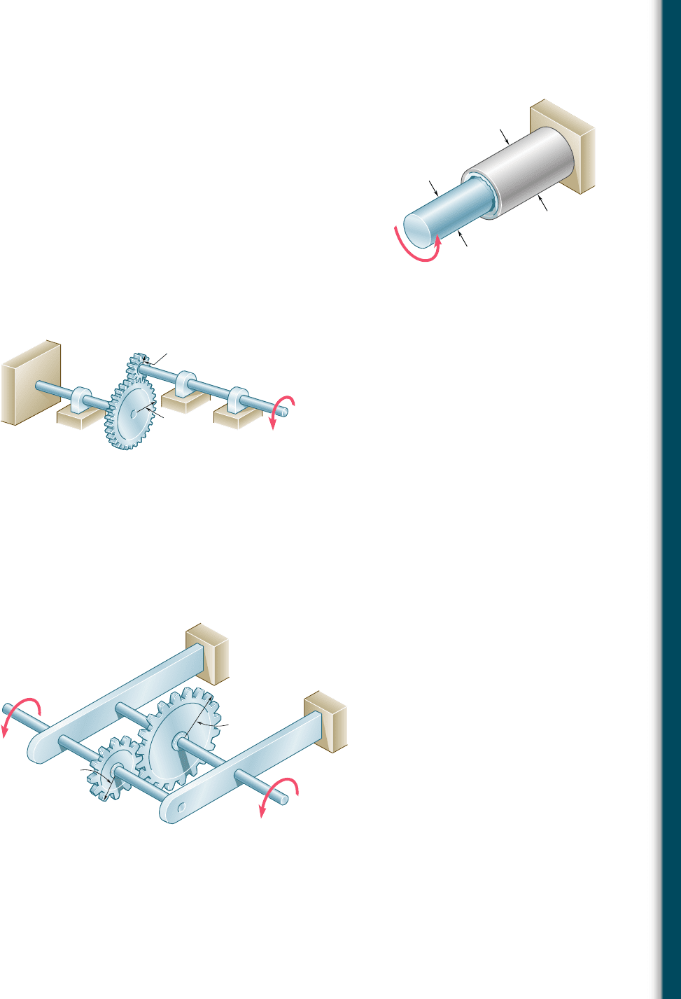
3.19 The solid rod AB has a diameter d
AB
5 60 mm. The pipe CD has
an outer diameter of 90 mm and a wall thickness of 6 mm. Know-
ing that both the rod and the pipe are made of steel for which the
allowable shearing stress is 75 MPa, determine the largest torque
T that can be applied at A.
3.20 The solid rod AB has a diameter d
AB
5 60 mm and is made of a
steel for which the allowable shearing stress is 85 MPa. The pipe
CD, which has an outer diameter of 90 mm and a wall thickness
of 6 mm, is made of an aluminum for which the allowable shearing
stress is 54 MPa. Determine the largest torque T that can be
applied at A.
3.21 A torque of magnitude T 5 1000 N ? m is applied at D as shown.
Knowing that the diameter of shaft AB is 56 mm and that the
diameter of shaft CD is 42 mm, determine the maximum shearing
stress in (a) shaft AB, (b) shaft CD.
D
A
B
90 mm
d
AB
C
T
Fig. P3.19 and P3.20
A
100 mm
40 mm
C
B
D
T 1000 N · m
Fig. P3.21 and P3.22
3.22 A torque of magnitude T 5 1000 N ? m is applied at D as shown.
Knowing that the allowable shearing stress is 60 MPa in each shaft,
determine the required diameter of (a) shaft AB, (b) shaft CD.
3.23 Under normal operating conditions a motor exerts a torque of mag-
nitude T
F
5 1200 lb ? in. at F. Knowing that r
D
5 8 in., r
G
5
3 in., and the allowable shearing stress is 10.5 ksi in each shaft,
determine the required diameter of (a) shaft CDE, (b) shaft FGH.
F
T
E
H
E
A
B
D
C
G
r
G
r
D
T
F
Fig. P3.23 and P3.24
3.24 Under normal operating conditions a motor exerts a torque of mag-
nitude T
F
at F. The shafts are made of a steel for which the allow-
able shearing stress is 12 ksi and have diameters d
CDE
5 0.900 in.
and d
FGH
5 0.800 in. Knowing that r
D
5 6.5 in. and r
G
5 4.5 in.,
determine the largest allowable value of T
F
.
bee80288_ch03_140-219.indd Page 157 9/21/10 3:05:21 PM user-f499bee80288_ch03_140-219.indd Page 157 9/21/10 3:05:21 PM user-f499 /Users/user-f499/Desktop/Temp Work/Don't Delete Job/MHDQ251:Beer:201/ch03/Users/user-f499/Desktop/Temp Work/Don't Delete Job/MHDQ251:Beer:201/ch03
Apago PDF Enhancer
158
Torsion
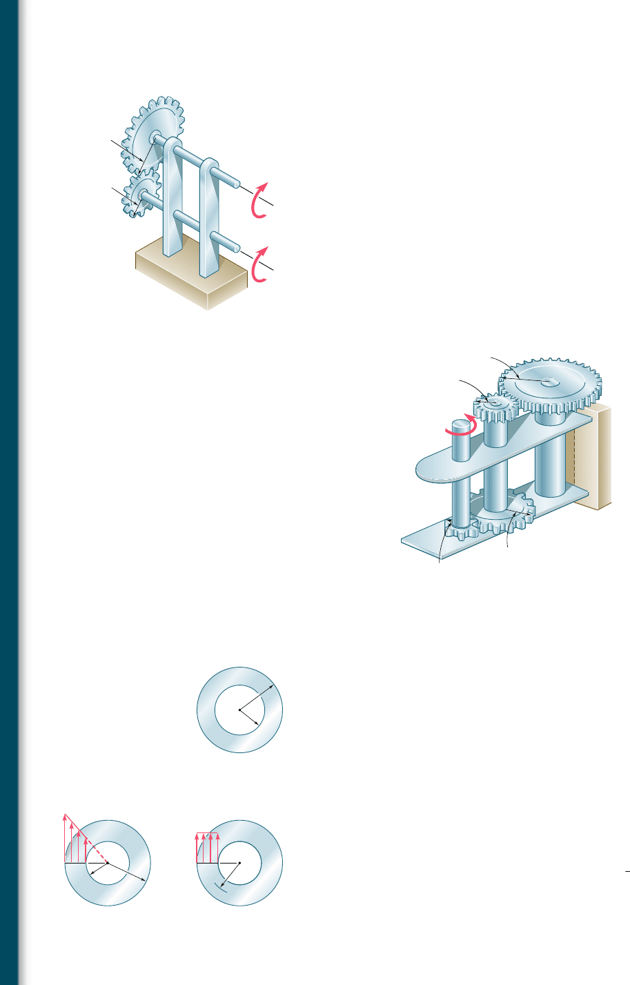
3.25 The two solid shafts are connected by gears as shown and are made
of a steel for which the allowable shearing stress is 8500 psi. Know-
ing that a torque of magnitude T
C
5 5 kip ? in. is applied at C and
that the assembly is in equilibrium, determine the required diam-
eter of (a) shaft BC, (b) shaft EF.
3.26 The two solid shafts are connected by gears as shown and are made
of a steel for which the allowable shearing stress is 7000 psi. Know-
ing the diameters of the two shafts are, respectively, d
BC
5 1.6 in.
and d
EF
5 1.25 in., determine the largest torque T
C
that can be
applied at C.
3.27 A torque of magnitude T 5 100 N ? m is applied to shaft AB of
the gear train shown. Knowing that the diameters of the three solid
shafts are, respectively, d
AB
5 21 mm, d
CD
5 30 mm, and d
EF
5
40 mm, determine the maximum shearing stress in (a) shaft AB,
(b) shaft CD, (c) shaft EF.
B
4 in.
2.5 in.
E
G
H
A
D
F
C
T
C
T
F
Fig. P3.25 and P3.26
C
B
F
D
A
30 mm
25 mm
60 mm
75 mm
E
T
Fig. P3.27 and P3.28
3.28 A torque of magnitude T 5 120 N ? m is applied to shaft AB of
the gear train shown. Knowing that the allowable shearing stress
is 75 MPa in each of the three solid shafts, determine the required
diameter of (a) shaft AB, (b) shaft CD, (c) shaft EF.
3.29 (a) For a given allowable shearing stress, determine the ratio Tyw
of the maximum allowable torque T and the weight per unit length
w for the hollow shaft shown. (b) Denoting by (Tyw)
0
the value of
this ratio for a solid shaft of the same radius c
2
, express the ratio
Tyw for the hollow shaft in terms of (Tyw)
0
and c
1
yc
2
.
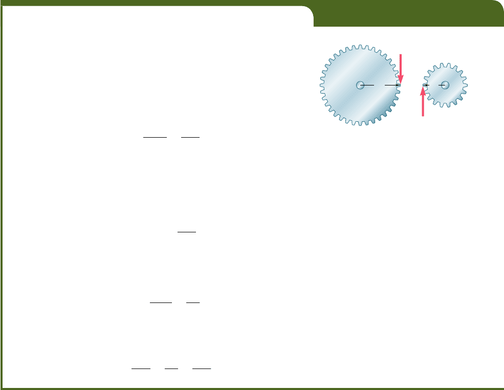
3.30 While the exact distribution of the shearing stresses in a hollow cylin-
drical shaft is as shown in Fig. P3.30a, an approximate value can be
obtained for t
max
by assuming that the stresses are uniformly distrib-
uted over the area A of the cross section, as shown in Fig. P3.30b,
and then further assuming that all of the elementary shearing forces
act at a distance from O equal to the mean radius
1
2
(c
1
1 c
2
) of the
cross section. This approximate value t
0
5 TyAr
m
, where T is the
applied torque. Determine the ratio t
max
yt
0
of the true value of
the maximum shearing stress and its approximate value t
0
for val-
ues of c
1
yc
2
respectively equal to 1.00, 0.95, 0.75, 0.50 and 0.
c
2
c
1
Fig. P3.29
O
O
c
1
max
r
m
c
2
0
(a) (b)
Fig. P3.30
bee80288_ch03_140-219.indd Page 158 11/2/10 3:06:37 PM user-f499bee80288_ch03_140-219.indd Page 158 11/2/10 3:06:37 PM user-f499 /Users/user-f499/Desktop/Temp Work/Don't Delete Job/MHDQ251:Beer:201/ch03/Users/user-f499/Desktop/Temp Work/Don't Delete Job/MHDQ251:Beer:201/ch03
Apago PDF Enhancer
159
3.5 ANGLE OF TWIST IN THE ELASTIC RANGE
In this section, a relation will be derived between the angle of twist f
of a circular shaft and the torque T exerted on the shaft. The entire shaft
will be assumed to remain elastic. Considering first the case of a shaft
of length L and of uniform cross section of radius c subjected to a torque
T at its free end (Fig. 3.20), we recall from Sec. 3.3 that the angle of
twist f and the maximum shearing strain g
max
are related as follows:
g
max
5
c
f
L
(3.3)
But, in the elastic range, the yield stress is not exceeded anywhere
in the shaft, Hooke’s law applies, and we have g
max
5 t
max
yG or,
recalling Eq. (3.9),
g
max
5
t
max
G
5
Tc
JG
(3.15)
Equating the right-hand members of Eqs. (3.3) and (3.15), and solv-
ing for f, we write
f 5
T
L
JG
(3.16)
where f is expressed in radians. The relation obtained shows that,
within the elastic range, the angle of twist f is proportional to the
torque T applied to the shaft. This is in accordance with the experi-
mental evidence cited at the beginning of Sec. 3.3.
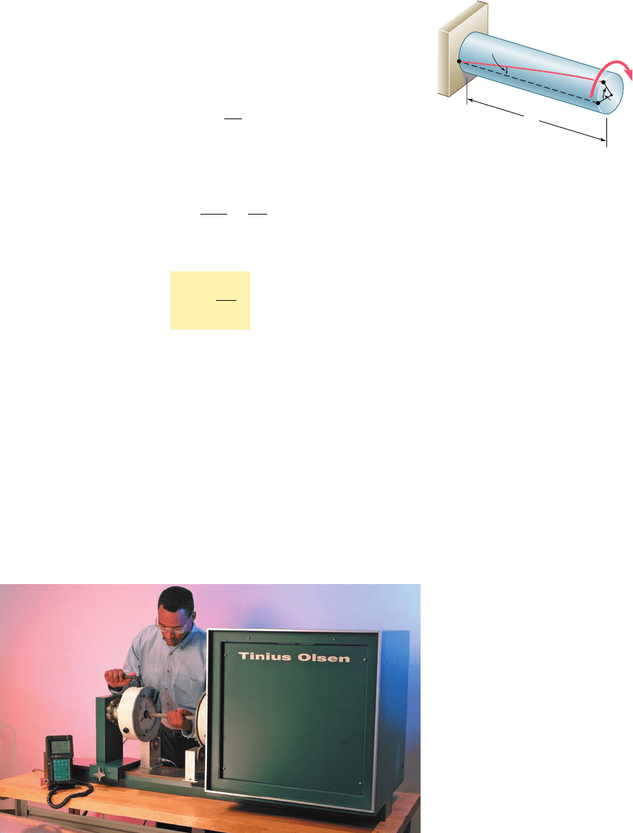
Equation (3.16) provides us with a convenient method for
determining the modulus of rigidity of a given material. A specimen
of the material, in the form of a cylindrical rod of known diameter
and length, is placed in a torsion testing machine (Photo 3.3). Torques
of increasing magnitude T are applied to the specimen, and the
corresponding values of the angle of twist f in a length L of the
specimen are recorded. As long as the yield stress of the material is
not exceeded, the points obtained by plotting f against T will fall on
a straight line. The slope of this line represents the quantity JGyL,
from which the modulus of rigidity G may be computed.
3.5 Angle of Twist in the Elastic Range
Photo 3.3 Torsion testing machine.
L
T
c
max
Fig. 3.20 Angle of twist f.
bee80288_ch03_140-219.indd Page 159 9/21/10 3:05:30 PM user-f499bee80288_ch03_140-219.indd Page 159 9/21/10 3:05:30 PM user-f499 /Users/user-f499/Desktop/Temp Work/Don't Delete Job/MHDQ251:Beer:201/ch03/Users/user-f499/Desktop/Temp Work/Don't Delete Job/MHDQ251:Beer:201/ch03

Apago PDF Enhancer
160
EXAMPLE 3.02
What torque should be applied to the end of the shaft of Example 3.01
to produce a twist of 28? Use the value G 5 77 GPa for the modulus of
rigidity of steel.
Solving Eq. (3.16) for T, we write
T 5
J
G
L
f
Substituting the given values
G
5 77 3 10
9
P
a
L 5 1
.
5 m
f 5 2°
a
2p rad
360°
b
5 34.9 3 10
23
rad
and recalling from Example 3.01 that, for the given cross section,
J 5 1.021 3 10
26
m
4
we have
T 5
J
G
L
f 5
11.021 3 10
2
6
m
4
2 177 3 10
9
Pa2
1
.
5 m
134.9 3 10
23
rad2
T 5 1
.
829 3 10
3
N ? m 5 1
.
829 kN ? m
EXAMPLE 3.03
What angle of twist will create a shearing stress of 70 MPa on the inner
surface of the hollow steel shaft of Examples 3.01 and 3.02?
The method of attack for solving this problem that first comes to
mind is to use Eq. (3.10) to find the torque T corresponding to the given
value of t, and Eq. (3.16) to determine the angle of twist f corresponding
to the value of T just found.
A more direct solution, however, may be used. From Hooke’s law,
we first compute the shearing strain on the inner surface of the shaft:
g
min
5
t
min
G
5
70 3 10
6
Pa
77
3
10
9
Pa
5 909 3 10
26
Recalling Eq. (3.2), which was obtained by expressing the length of arc
AA9 in Fig. 3.13c in terms of both g and f, we have
f 5
Lg
min
c
1
5
1500 mm
20 mm
1909 3 10
26
25 68.2 3 10
23
rad
To obtain the angle of twist in degrees, we write
f 5 168.2 3 10
23
rad2
a
360°
2p rad
b
5 3.91°
Formula (3.16) for the angle of twist can be used only if the
shaft is homogeneous (constant G), has a uniform cross section, and
is loaded only at its ends. If the shaft is subjected to torques at loca-
tions other than its ends, or if it consists of several portions with
various cross sections and possibly of different materials, we must
divide it into component parts that satisfy individually the required
bee80288_ch03_140-219.indd Page 160 11/2/10 12:48:17 AM user-f499bee80288_ch03_140-219.indd Page 160 11/2/10 12:48:17 AM user-f499 /Users/user-f499/Desktop/Temp Work/Don't Delete Job/MHDQ251:Beer:201/ch03/Users/user-f499/Desktop/Temp Work/Don't Delete Job/MHDQ251:Beer:201/ch03
Apago PDF Enhancer
161
conditions for the application of formula (3.16). In the case of the
shaft AB shown in Fig. 3.21, for example, four different parts should
be considered: AC, CD, DE, and EB. The total angle of twist of the
shaft, i.e., the angle through which end A rotates with respect to end
B, is obtained by adding algebraically the angles of twist of each
component part. Denoting, respectively, by T
i
, L
i
, J
i
, and G
i
the inter-
nal torque, length, cross-sectional polar moment of inertia, and mod-
ulus of rigidity corresponding to part i, the total angle of twist of the
shaft is expressed as
f 5
a
i
T
i
L
i
J
i
G
i
(3.17)
The internal torque T
i
in any given part of the shaft is obtained by
passing a section through that part and drawing the free-body dia-
gram of the portion of shaft located on one side of the section. This
procedure, which has already been explained in Sec. 3.4 and illus-
trated in Fig. 3.16, is applied in Sample Prob. 3.3.
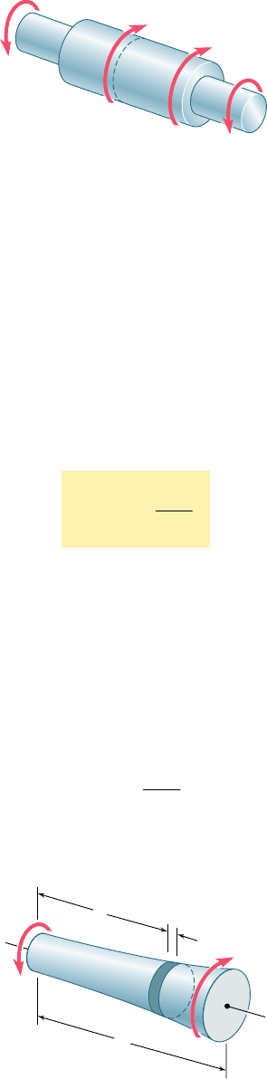
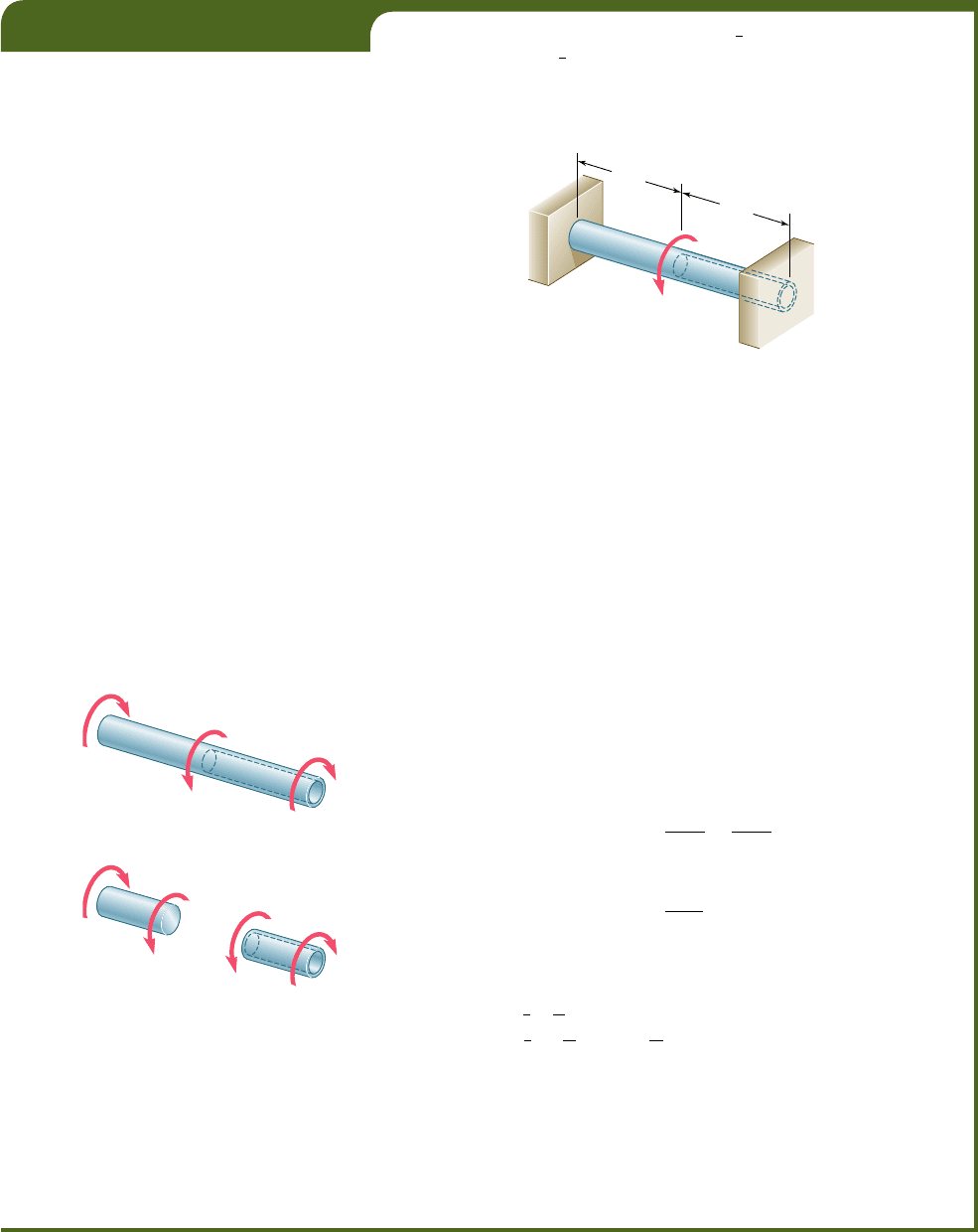
In the case of a shaft with a variable circular cross section, as
shown in Fig. 3.22, formula (3.16) may be applied to a disk of thick-
ness dx. The angle by which one face of the disk rotates with respect
to the other is thus
d
f 5
T dx
JG
3.5 Angle of Twist in the Elastic Range
T
C
T
D
T
A
T
B
A
C
B
E
D
Fig. 3.21 Multiple sections and multiple
torques.
x
A
dx
B
L
T'
T
Fig. 3.22 Shaft with variable cross
section.
bee80288_ch03_140-219.indd Page 161 9/21/10 3:05:36 PM user-f499bee80288_ch03_140-219.indd Page 161 9/21/10 3:05:36 PM user-f499 /Users/user-f499/Desktop/Temp Work/Don't Delete Job/MHDQ251:Beer:201/ch03/Users/user-f499/Desktop/Temp Work/Don't Delete Job/MHDQ251:Beer:201/ch03
Apago PDF Enhancer
162
Torsion
where J is a function of x, which may be determined. Integrating in
x from 0 to L, we obtain the total angle of twist of the shaft:
f 5
#
L
0
T dx
JG
(3.18)
The shaft shown in Fig. 3.20, which was used to derive formula
(3.16), and the shaft of Fig. 3.15, which was discussed in Examples
3.02 and 3.03, both had one end attached to a fixed support. In each
case, therefore, the angle of twist f of the shaft was equal to the
angle of rotation of its free end. When both ends of a shaft rotate,
however, the angle of twist of the shaft is equal to the angle through
which one end of the shaft rotates with respect to the other. Con-
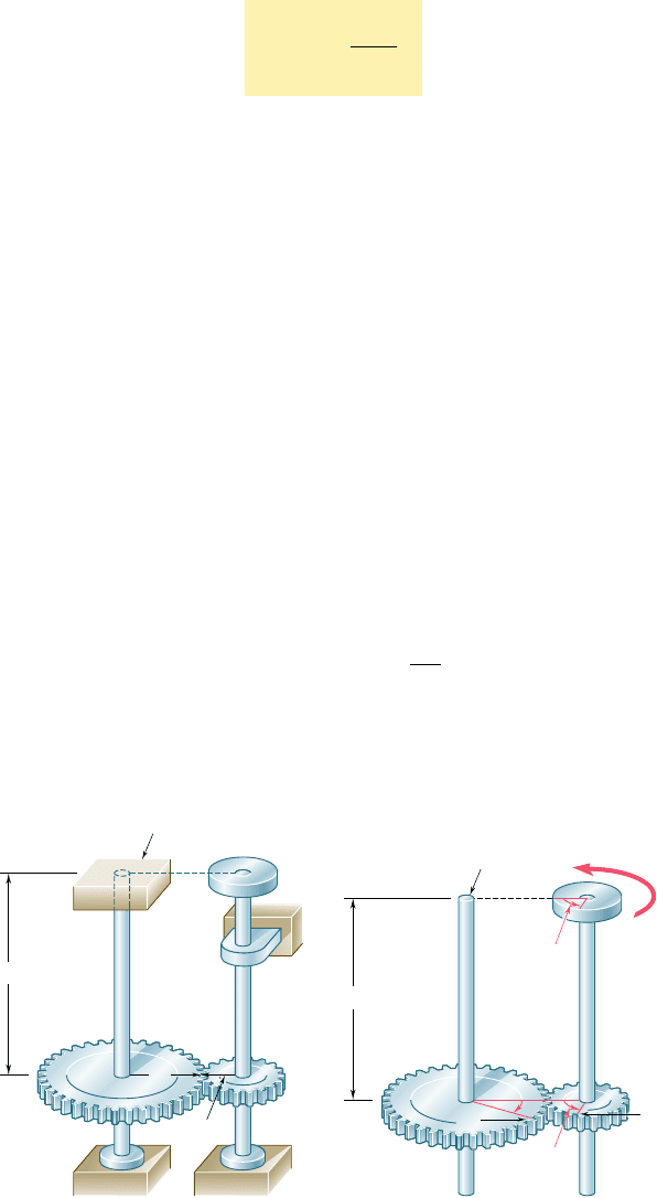
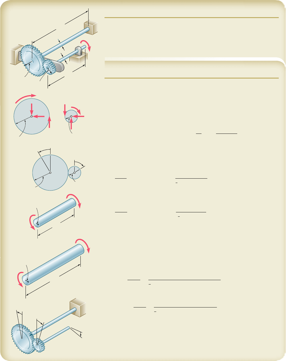
sider, for instance, the assembly shown in Fig. 3.23a, consisting of
two elastic shafts AD and BE, each of length L, radius c, and modu-
lus of rigidity G, which are attached to gears meshed at C. If a
torque T is applied at E (Fig. 3.23b), both shafts will be twisted.
Since the end D of shaft AD is fixed, the angle of twist of AD is
measured by the angle of rotation f
A
of end A. On the other hand,
since both ends of shaft BE rotate, the angle of twist of BE is equal
to the difference between the angles of rotation f
B
and f
E
, i.e., the
angle of twist is equal to the angle through which end E rotates with
respect to end B. Denoting this relative angle of rotation by f
EyB
,
we write
f
E
y
B
5 f
E
2 f
B
5
T
L
J
G
(a)
C
B
L
r
B
A
r
A
E
Fixed support
D
(b)
C'
'
T
E
B
C
Fixed end
B
L
A
D
A
C'
E
Fig. 3.23 Gear assembly.
bee80288_ch03_140-219.indd Page 162 9/21/10 3:05:40 PM user-f499bee80288_ch03_140-219.indd Page 162 9/21/10 3:05:40 PM user-f499 /Users/user-f499/Desktop/Temp Work/Don't Delete Job/MHDQ251:Beer:201/ch03/Users/user-f499/Desktop/Temp Work/Don't Delete Job/MHDQ251:Beer:201/ch03
Apago PDF Enhancer
EXAMPLE 3.04
For the assembly of Fig. 3.23, knowing that r
A
5 2r
B
, determine the angle
of rotation of end E of shaft BE when the torque T is applied at E.
We first determine the torque T
AD
exerted on shaft AD. Observing
that equal and opposite forces F and F9 are applied on the two gears at
C (Fig. 3.24), and recalling that r
A
5 2r
B
, we conclude that the torque
exerted on shaft AD is twice as large as the torque exerted on shaft BE;
thus, T
AD
5 2T.
Since the end D of shaft AD is fixed, the angle of rotation f
A
of gear
A is equal to the angle of twist of the shaft and is obtained by writing
f
A
5
T
AD
L
JG
5
2T
L
JG
Observing that the arcs CC9 and CC0 in Fig. 3.26b must be equal, we
write r
A
f
A
5 r
B
f
B
and obtain
f
B
5 1r
A
y
r
B
2f
A
5 2f
A
We have, therefore,
f
B
5 2f
A
5
4TL
JG
Considering now shaft BE, we recall that the angle of twist of the
shaft is equal to the angle f
EyB
through which end E rotates with respect
to end B. We have
f
E
y
B
5
T
BE
L
JG
5
T
L
JG
The angle of rotation of end E is obtained by writing
f
E
5 f
B
1 f
E
y
B
5
4TL
JG
1
TL
JG
5
5TL
JG
A
B
C
F
F'
r
A
r
B
Fig. 3.24
3.6 STATICALLY INDETERMINATE SHAFTS
You saw in Sec. 3.4 that, in order to determine the stresses in a shaft,
it was necessary to first calculate the internal torques in the various
parts of the shaft. These torques were obtained from statics by draw-
ing the free-body diagram of the portion of shaft located on one side
of a given section and writing that the sum of the torques exerted
on that portion was zero.
There are situations, however, where the internal torques cannot
be determined from statics alone. In fact, in such cases the external
torques themselves, i.e., the torques exerted on the shaft by the supports
and connections, cannot be determined from the free-body diagram of
the entire shaft. The equilibrium equations must be complemented by
relations involving the deformations of the shaft and obtained by con-
sidering the geometry of the problem. Because statics is not sufficient
to determine the external and internal torques, the shafts are said to
be statically indeterminate. The following example, as well as Sample
Prob. 3.5, will show how to analyze statically indeterminate shafts.
163
bee80288_ch03_140-219.indd Page 163 9/21/10 9:15:47 PM user-f499bee80288_ch03_140-219.indd Page 163 9/21/10 9:15:47 PM user-f499 /Users/user-f499/Desktop/Temp Work/Don't Delete Job/MHDQ251:Beer:201/ch03/Users/user-f499/Desktop/Temp Work/Don't Delete Job/MHDQ251:Beer:201/ch03
Apago PDF Enhancer
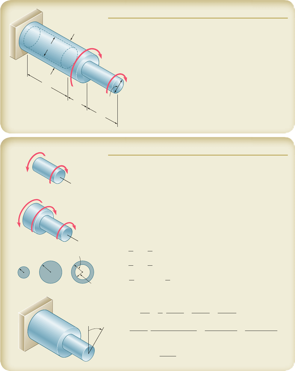
(a)
(b)
(c)
T
B
T
1
T
2
T
A
T
B
T
A
A
A
C
B
B
90 lb
·
ft
Fig. 3.26
164
EXAMPLE 3.05
A circular shaft AB consists of a 10-in.-long,
7
8
-in.-diameter steel cylinder,
in which a 5-in.-long,
5
8
-in.-diameter cavity has been drilled from end B.
The shaft is attached to fixed supports at both ends, and a 90 lb ? ft torque
is applied at its midsection (Fig. 3.25). Determine the torque exerted on
the shaft by each of the supports.
5 in.
5 in.
90 lb
·
ft
B
A
Fig. 3.25
Drawing the free-body diagram of the shaft and denoting by T
A
and
T
B
the torques exerted by the supports (Fig. 3.26a), we obtain the equi-
librium equation
T
A
1 T
B
5 90 lb ? ft
Since this equation is not sufficient to determine the two unknown torques
T
A
and T
B
, the shaft is statically indeterminate.
However, T
A
and T
B
can be determined if we observe that the total
angle of twist of shaft AB must be zero, since both of its ends are
restrained. Denoting by f
1
and f
2
, respectively, the angles of twist of
portions AC and CB, we write
f 5 f
1
1 f
2
5 0
From the free-body diagram of a small portion of shaft including end A
(Fig. 3.26b), we note that the internal torque T
1
in AC is equal to T
A
; from
the free-body diagram of a small portion of shaft including end B (Fig.
3.26c), we note that the internal torque T
2
in CB is equal to T
B
. Recalling
Eq. (3.16) and observing that portions AC and CB of the shaft are twisted
in opposite senses, we write
f 5 f
1
1 f
2
5
T
A
L
1
J
1
G
2
T
B
L
2
J
2
G
5 0
Solving for T
B
, we have
T
B
5
L
1
J
2
L
2
J
1
T
A
Substituting the numerical data gives
L
1
5 L
2
5 5 in.
J
1
5
1
2
p1
7
16
in.2
4
5 57.6 3 10
23
in
4
J
2
5
1
2
p 31
7
16
in.2
4
2 1
5
16
in.2
4
45 42.6 3 10
23
in
4
we obtain
T
B
5 0.740 T
A
Substituting this expression into the original equilibrium equation, we
write
1.740 T
A
5 90 lb ? ft
T
A
5 51.7 lb ? ft T
B
5 38.3 lb ? ft
bee80288_ch03_140-219.indd Page 164 9/21/10 3:05:46 PM user-f499bee80288_ch03_140-219.indd Page 164 9/21/10 3:05:46 PM user-f499 /Users/user-f499/Desktop/Temp Work/Don't Delete Job/MHDQ251:Beer:201/ch03/Users/user-f499/Desktop/Temp Work/Don't Delete Job/MHDQ251:Beer:201/ch03
Apago PDF Enhancer
165
B
D
C
A
0.2 m
0.4 m
0.6 m
60 mm
30 mm
250 N · m
2000 N · m
44 mm
SOLUTION
Since the shaft consists of three portions AB, BC, and CD, each of uniform cross
section and each with a constant internal torque, Eq. (3.17) may be used.
Statics. Passing a section through the shaft between A and B and
using the free body shown, we find
©M
x
5 0:
1
250 N ? m
2
2 T
AB
5 0T
AB
5 250 N ? m
Passing now a section between B and C, we have
©M
x
5 0:
1
250 N ? m
2
1
1
2000 N ? m
2
2 T
BC
5 0T
BC
5 2250 N ? m
Since no torque is applied at C,
T
CD
5 T
BC
5 2250 N ? m
Polar Moments of Inertia
J
AB
5
p
2
c
4
5
p
2
10.015 m2
4
5 0.0795 3 10
26
m
4
J
BC
5
p
2
c
4
5
p
2
10.030 m2
4
5 1.272 3 10
26
m
4
J
CD
5
p
2
1c
2
4
2 c
1
4
25
p
2
310.030 m2
4
2 10.022 m2
4
45 0.904 3 10
26
m
4
Angle of Twist. Using Eq. (3.17) and recalling that G 5 77 GPa for
the entire shaft, we have
f
A
5
a
i
T
i
L
i
J
i
G
5
1
G
a
T
AB
L
AB
J
AB
1
T
BC
L
BC
J
BC
1
T
CD
L
CD
J
CD
b
f
A
5
1
77 GPa
c
1250 N ? m2
10.4 m2
0.0795 3 10
26
m
4
1
122502
10.22
1.272 3 10
26
1
122502
10.62
0.904 3 10
26
d
5 0.01634 1 0.00459 1 0.01939 5 0.0403 ra
d
f
A
5 10.0403 rad2
360°
2p rad
f
A
5 2.31°b
A
x
T
AB
250 N · m
B
A
T
BC
2000 N · m
250 N · m
x
22 mm
15 mm
30 mm
30 mm
AB
BC
CD
C
B
A
A
D
SAMPLE PROBLEM 3.3
The horizontal shaft AD is attached to a fixed base at D and is subjected to
the torques shown. A 44-mm-diameter hole has been drilled into portion
CD of the shaft. Knowing that the entire shaft is made of steel for which
G 5 77 GPa, determine the angle of twist at end A.
bee80288_ch03_140-219.indd Page 165 11/2/10 1:29:33 AM user-f499bee80288_ch03_140-219.indd Page 165 11/2/10 1:29:33 AM user-f499 /Users/user-f499/Desktop/Temp Work/Don't Delete Job/MHDQ251:Beer:201/ch03/Users/user-f499/Desktop/Temp Work/Don't Delete Job/MHDQ251:Beer:201/ch03
Apago PDF Enhancer
166
24 in.
B
c
0.375 in.
A
T
AB
T
0
T
AB
T
0
36 in.
T
CD
T
CD
c 0.5 in.
D
C
C
B
D
A
A
10.48
B
8.26
C
2.95
24 in.
0.75 in.
36 in.
0.875 in.
2.45 in.
A
T
0
D
C
B
1 in.
SAMPLE PROBLEM 3.4
Two solid steel shafts are connected by the gears shown. Knowing that for
each shaft G 5 11.2 3 10
6
psi and that the allowable shearing stress is 8 ksi,
determine (a) the largest torque T
0
that may be applied to end A of shaft AB,
(b) the corresponding angle through which end A of shaft AB rotates.
SOLUTION
Statics. Denoting by F the magnitude of the tangential force between
gear teeth, we have
Gear B. oM
B
5 0: F
1
0.875 in.
2
2 T
0
5 0
T
CD
5 2.8T
0
(1)
Gear C. oM
C
5 0: F
1
2.45 in.
2
2 T
CD
5 0
Kinematics. Noting that the peripheral motions of the gears are equal,
we write
r
B
f
B
5 r
C
f
C
f
B
5 f
C
r
C
r
B
5 f
C
2.45 in.
0.875 in.
5 2.8f
C
(2)
a. Torque T
0
Shaft AB. With T
AB
5 T
0
and c 5 0.375 in., together with a maximum
permissible shearing stress of 8000 psi, we write
t 5
T
AB
c
J
8000 psi 5
T
0
1
0.375 in.
2
1
2
p
1
0.375 in.
2
4
T
0
5 663 lb ? in.
◀
Shaft CD. From (1) we have T
CD
5 2.8T
0
. With c 5 0.5 in. and
t
all
5 8000 psi, we write
t 5
T
CD
c
J
8000 psi 5
2.8T
0
1
0.5 in.
2
1
2
p
1
0.5 in.
2
4
T
0
5 561 lb ? in.
◀
Maximum Permissible Torque. We choose the smaller value obtained
for T
0
T
0
5 561 lb ? in.
◀
b. Angle of Rotation at End A. We first compute the angle of twist
for each shaft.
Shaft AB. For T
AB
5 T
0
5 561 lb ? in., we have
f
A
y
B
5
T
AB
L
JG
5
1561 lb ? in.2
124 in.2
1
2
p 10.375 in.2
4
111.2 3 10
6
psi2
5 0.0387 rad 5 2.22°
Shaft CD. T
CD
5 2.8T
0
5 2.8(561 lb ? in.)
f
C
y
D
5
T
CD
L
JG
5
2.8
1
561 lb ? in.
2
1
36 in.
2
1
2
p10.5 in.2
4
111.2 3 10
6
psi2
5 0.0514 rad 5 2.95°
Since end D of shaft CD is fixed, we have f
C
5 f
C@D
5 2.958. Using
(2), we find the angle of rotation of gear B to be
f
B
5 2.8f
C
5 2.8
1
2.95°
2
5 8.26°
For end A of shaft AB, we have
f
A
5
f
B
1
f
A
y
B
5 8.26° 1 2.22°
f
A
5 10.48°
◀
C
C
B
B
r
B
0.875 in.
r
C
2.45 in.
C
T
CD
F
F
r
B
0.875 in.
r
C
2.45 in.
B
T
AB
T
0
bee80288_ch03_140-219.indd Page 166 9/21/10 9:15:56 PM user-f499bee80288_ch03_140-219.indd Page 166 9/21/10 9:15:56 PM user-f499 /Users/user-f499/Desktop/Temp Work/Don't Delete Job/MHDQ251:Beer:201/ch03/Users/user-f499/Desktop/Temp Work/Don't Delete Job/MHDQ251:Beer:201/ch03