Beer F.P., Johnston E.R., DeWolf J.T., Mazurek D.F. Mechanics of Materials
Подождите немного. Документ загружается.

Apago PDF Enhancer
97
Since the element had originally a unit volume, the quantity e repre-
sents the change in volume per unit volume; it is referred to as the dila-
tation of the material. Substituting for P
x
, P
y
, and P
z
from Eqs. (2.28)
into (2.30), we write
e 5
s
x
1 s
y
1 s
z
E
2
2n
1
s
x
1 s
y
1 s
z
2
E
e 5
1 2 2n
E
1s
x
1 s
y
1 s
z
2
(2.31)†
A case of special interest is that of a body subjected to a uni-
form hydrostatic pressure p. Each of the stress components is then
equal to 2p and Eq. (2.31) yields
e 52
3
1
1 2 2n
2
E
p
(2.32)
Introducing the constant
k
5
E
3
1
1 2 2n
2
(2.33)
we write Eq. (2.32) in the form
e 52
p
k
(2.34)
The constant k is known as the bulk modulus or modulus of compres-
sion of the material. It is expressed in the same units as the modulus
of elasticity E, that is, in pascals or in psi.
Observation and common sense indicate that a stable material
subjected to a hydrostatic pressure can only decrease in volume; thus
the dilatation e in Eq. (2.34) is negative, from which it follows that
the bulk modulus k is a positive quantity. Referring to Eq. (2.33), we
conclude that 1 2 2n . 0, or n ,
1
2
. On the other hand, we recall
from Sec. 2.11 that n is positive for all engineering materials. We
thus conclude that, for any engineering material,
0, n ,
1
2
(2.35)
We note that an ideal material having a value of v equal to zero could
be stretched in one direction without any lateral contraction. On the
other hand, an ideal material for which n 5
1
2
, and thus k 5 `, would
be perfectly incompressible (e 5 0). Referring to Eq. (2.31) we also
note that, since n ,
1
2
in the elastic range, stretching an engineering
material in one direction, for example in the x direction (s
x
. 0,
s
y
5 s
z
5 0), will result in an increase of its volume (e . 0).‡
*2.13 Dilatation; Bulk Modulus
†Since the dilatation e represents a change in volume, it must be independent of the ori-
entation of the element considered. It then follows from Eqs. (2.30) and (2.31) that the
quantities P
x
1 P
y
1 P
z
and s
x
1 s
y
1 s
z
are also independent of the orientation of the
element. This property will be verified in Chap. 7.
‡However, in the plastic range, the volume of the material remains nearly constant.
bee80288_ch02_052-139.indd Page 97 11/8/10 9:34:11 PM user-f494bee80288_ch02_052-139.indd Page 97 11/8/10 9:34:11 PM user-f494 volume 201/FREE048/work%0/indd%0/volume 201/FREE048/work%0/indd%0/
Apago PDF Enhancer
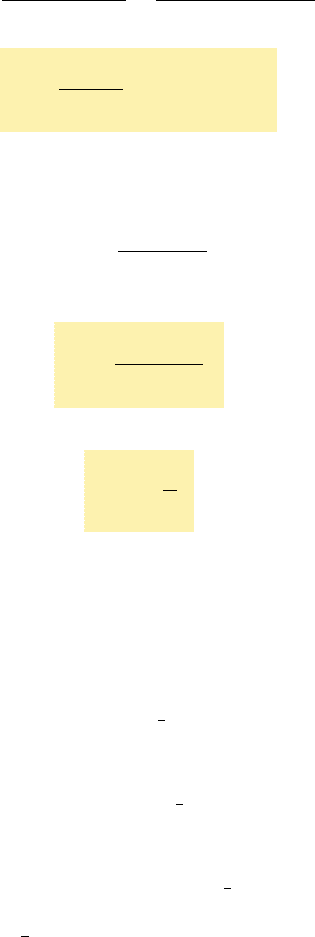
2.14 SHEARING STRAIN
When we derived in Sec. 2.12 the relations (2.28) between normal
stresses and normal strains in a homogeneous isotropic material, we
assumed that no shearing stresses were involved. In the more gen-
eral stress situation represented in Fig. 2.41, shearing stresses t
xy
,
t
yz
, and t
zx
will be present (as well, of course, as the corresponding
shearing stresses t
yx
, t
zy
, and t
xz
). These stresses have no direct
effect on the normal strains and, as long as all the deformations
involved remain small, they will not affect the derivation nor
the validity of the relations (2.28). The shearing stresses, however,
will tend to deform a cubic element of material into an oblique
parallelepiped.
98
Determine the change in volume DV of the steel block shown in Fig. 2.40,
when it is subjected to the hydrostatic pressure p 5 180 MPa. Use E 5
200 GPa and n 5 0.29.
From Eq. (2.33), we determine the bulk modulus of steel,
k
5
E
3
1
1 2 2n
2
5
200
G
Pa
3
1
1 2 0.58
2
5 158.7 GPa
and, from Eq. (2.34), the dilatation,
e 52
p
k
52
180
MPa
158.7 GPa
521.134 3 10
23
Since the volume V of the block in its unstressed state is
V 5 (80 mm)(40 mm)(60 mm) 5 192 3 10
3
mm
3
and since e represents the change in volume per unit volume, e 5 DVyV,
we have
DV 5 eV 5 (21.134 3 10
23
)(192 3 10
3
mm
3
)
DV 5 2218 mm
3
EXAMPLE 2.09
zy
yz
yx
zx
z
x
y
z
y
x
xy
xz
Q
Fig. 2.41 General state of stress.
bee80288_ch02_052-139.indd Page 98 11/8/10 8:07:24 PM user-f499bee80288_ch02_052-139.indd Page 98 11/8/10 8:07:24 PM user-f499 /Users/user-f499/Desktop/Temp Work/Don't Delete Job/MHDQ251:Beer:201/ch02/Users/user-f499/Desktop/Temp Work/Don't Delete Job/MHDQ251:Beer:201/ch02
Apago PDF Enhancer
99
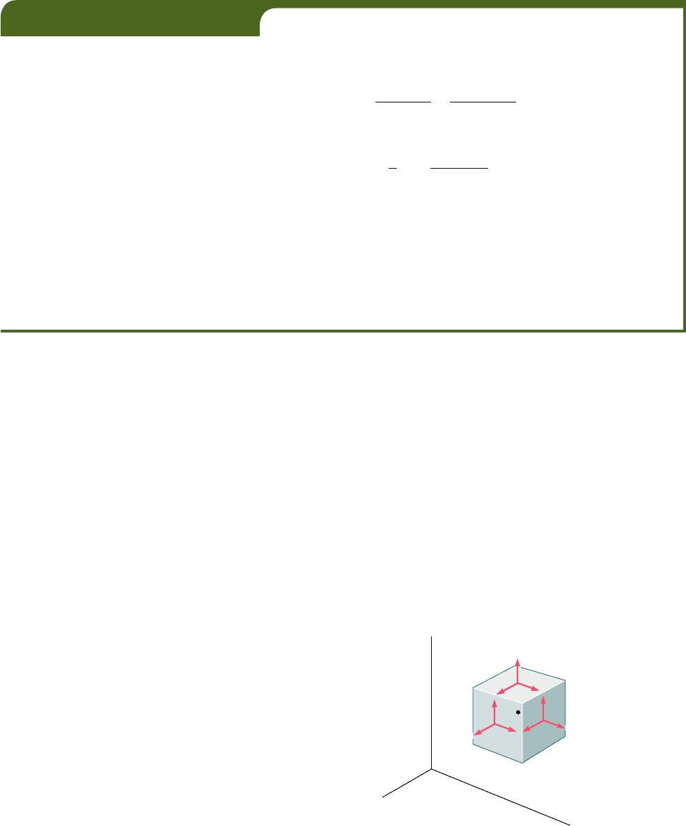
Consider first a cubic element of side one (Fig. 2.42) subjected
to no other stresses than the shearing stresses t
xy
and t
yx
applied to
faces of the element respectively perpendicular to the x and y axes.
(We recall from Sec. 1.12 that t
xy
5 t
yx
.) The element is observed
to deform into a rhomboid of sides equal to one (Fig. 2.43). Two of
the angles formed by the four faces under stress are reduced from
p
2
to
p
2
2 g
x
y
, while the other two are increased from
p
2
to
p
2
1 g
xy
,
The small angle g
xy
(expressed in radians) defines the shearing strain
corresponding to the x and y directions. When the deformation
involves a reduction of the angle formed by the two faces oriented
respectively toward the positive x and y axes (as shown in Fig. 2.43),
the shearing strain g
xy
is said to be positive; otherwise, it is said to
be negative.
We should note that, as a result of the deformations of the
other elements of the material, the element under consideration can
also undergo an overall rotation. However, as was the case in our
study of normal strains, we are concerned here only with the actual
deformation of the element, and not with any possible superimposed
rigid-body displacement.†
Plotting successive values of t
xy
against the corresponding val-
ues of g
xy
, we obtain the shearing stress-strain diagram for the mate-
rial under consideration. This can be accomplished by carrying out
a torsion test, as you will see in Chap. 3. The diagram obtained is
similar to the normal stress-strain diagram obtained for the same
material from the tensile test described earlier in this chapter. How-
ever, the values obtained for the yield strength, ultimate strength,
etc., of a given material are only about half as large in shear as they
are in tension. As was the case for normal stresses and strains, the
initial portion of the shearing stress-strain diagram is a straight line.
For values of the shearing stress that do not exceed the proportional
yx
yx
z
y
x
xy
xy
1
1
1
Fig. 2.42 Cubic element subjected to
shearing stresses.
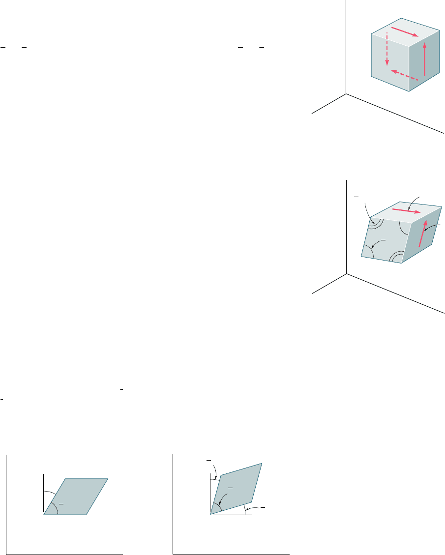
†In defining the strain g
xy
, some authors arbitrarily assume that the actual deformation of
the element is accompanied by a rigid-body rotation such that the horizontal faces of the
element do not rotate. The strain g
xy
is then represented by the angle through which the
other two faces have rotated (Fig. 2.44). Others assume a rigid-body rotation such that
the horizontal faces rotate through
1
2
g
xy
counterclockwise and the vertical faces through
1
2
g
xy
clockwise (Fig. 2.45). Since both assumptions are unnecessary and may lead to confu-
sion, we prefer in this text to associate the shearing strain g
xy
with the change in the angle
formed by the two faces, rather than with the rotation of a given face under restrictive
conditions.
1
1
z
y
x
yx
xy
xy
2
xy
2
Fig. 2.43 Deformation of cubic
element due to shearing stresses.
y
x
xy
2
xy
Fig. 2.44
y
x
xy
2
xy
2
1
xy
2
1
Fig. 2.45
2.14 Shearing Strain
bee80288_ch02_052-139.indd Page 99 9/4/10 5:18:22 PM user-f499bee80288_ch02_052-139.indd Page 99 9/4/10 5:18:22 PM user-f499 /Users/user-f499/Desktop/Temp Work/Don't Delete Job/MHDQ251:Beer:201/ch02/Users/user-f499/Desktop/Temp Work/Don't Delete Job/MHDQ251:Beer:201/ch02
Apago PDF Enhancer
100
Stress and Strain—Axial Loading
limit in shear, we can therefore write for any homogeneous isotropic
material,
t
xy
5 Gg
xy
(2.36)
This relation is known as Hooke’s law for shearing stress and strain,
and the constant G is called the modulus of rigidity or shear modulus
of the material. Since the strain g
xy
was defined as an angle in radi-
ans, it is dimensionless, and the modulus G is expressed in the same
units as t
xy
, that is, in pascals or in psi. The modulus of rigidity G
of any given material is less than one-half, but more than one-third
of the modulus of elasticity E of that material.†
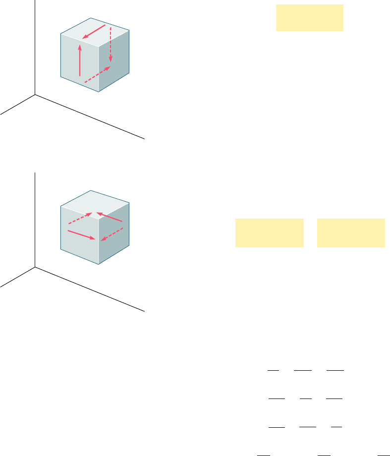
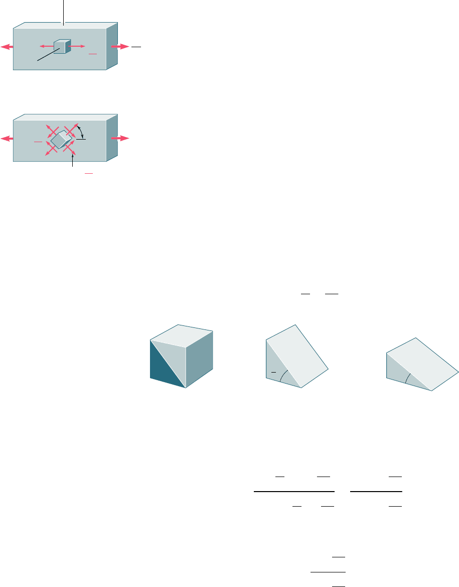
Considering now a small element of material subjected to
shearing stresses t
yz
and t
zy
(Fig. 2.46a), we define the shearing
strain g
yz
as the change in the angle formed by the faces under stress.
The shearing strain g
zx
is defined in a similar way by considering an
element subjected to shearing stresses t
zx
and t
xz
(Fig. 2.46b). For
values of the stress that do not exceed the proportional limit, we can
write the two additional relations
t
yz
5 Gg
yz
t
zx
5 Gg
zx
(2.37)
where the constant G is the same as in Eq. (2.36).
For the general stress condition represented in Fig. 2.41, and
as long as none of the stresses involved exceeds the corresponding
proportional limit, we can apply the principle of superposition and
combine the results obtained in this section and in Sec. 2.12. We
obtain the following group of equations representing the generalized
Hooke’s law for a homogeneous isotropic material under the most
general stress condition.
P
x
51
s
x
E
2
ns
y
E
2
ns
z
E
P
y
52
ns
x
E
1
s
y
E
2
ns
z
E
P
z
52
ns
x
E
2
ns
y
E
1
s
z
E
(2.38)
g
xy
5
t
xy
G
g
yz
5
t
yz
G
g
zx
5
t
zx
G
An examination of Eqs. (2.38) might lead us to believe that
three distinct constants, E, n, and G, must first be determined exper-
imentally, if we are to predict the deformations caused in a given
material by an arbitrary combination of stresses. Actually, only two
of these constants need be determined experimentally for any given
material. As you will see in the next section, the third constant can
then be obtained through a very simple computation.
yz
z
y
x
zy
(a)
z
y
x
zx
xz
(b)
Fig. 2.46
†See Prob. 2.91.
bee80288_ch02_052-139.indd Page 100 11/8/10 8:07:33 PM user-f499bee80288_ch02_052-139.indd Page 100 11/8/10 8:07:33 PM user-f499 /Users/user-f499/Desktop/Temp Work/Don't Delete Job/MHDQ251:Beer:201/ch02/Users/user-f499/Desktop/Temp Work/Don't Delete Job/MHDQ251:Beer:201/ch02
Apago PDF Enhancer
101
2.15 FURTHER DISCUSSION OF DEFORMATIONS
UNDER AXIAL LOADING; RELATION AMONG
E, N, AND G
We saw in Sec. 2.11 that a slender bar subjected to an axial tensile
load P directed along the x axis will elongate in the x direction
and contract in both of the transverse y and z directions. If
P
x
denotes the axial strain, the lateral strain is expressed as P
y
5
P
z
5 2nP
x
, where n is Poisson’s ratio. Thus, an element in the
shape of a cube of side equal to one and oriented as shown in Fig.
2.49a will deform into a rectangular parallelepiped of sides 1 1
P
x
, 1 2 nP
x
, and 1 2 nP
x
. (Note that only one face of the element
is shown in the figure.) On the other hand, if the element is ori-
ented at 458 to the axis of the load (Fig. 2.49b), the face shown in
the figure is observed to deform into a rhombus. We conclude that
the axial load P causes in this element a shearing strain g9 equal
to the amount by which each of the angles shown in Fig. 2.49b
increases or decreases.†
P
2.5 in.
2 in.
8 in.
Fig. 2.47
P
2 in.
0.04 in.
A
F
E
C
B
D
z
y
x
xy
␥
Fig. 2.48
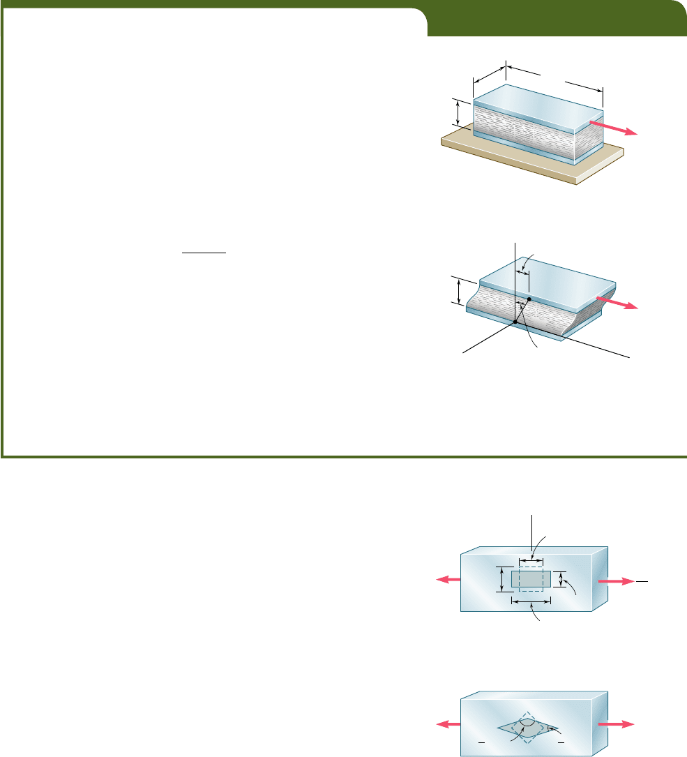
EXAMPLE 2.10A rectangular block of a material with a modulus of rigidity G 5 90 ksi
is bonded to two rigid horizontal plates. The lower plate is fixed, while
the upper plate is subjected to a horizontal force P (Fig. 2.47). Knowing
that the upper plate moves through 0.04 in. under the action of the force,
determine (a) the average shearing strain in the material, (b) the force P
exerted on the upper plate.
(a) Shearing Strain. We select coordinate axes centered at the
midpoint C of edge AB and directed as shown (Fig. 2.48). According to
its definition, the shearing strain g
xy
is equal to the angle formed by the
vertical and the line CF joining the midpoints of edges AB and DE. Not-
ing that this is a very small angle and recalling that it should be expressed
in radians, we write
g
xy
< tan g
xy
5
0.04 in.
2 i
n.
g
xy
5 0.020 rad
(b) Force Exerted on Upper Plate. We first determine the shear-
ing stress t
xy
in the material. Using Hooke’s law for shearing stress and
strain, we have
t
xy
5 Gg
xy
5 190 3 10
3
psi210.020 rad25 1800 psi
The force exerted on the upper plate is thus
P 5 t
xy
A 5 11800 psi218 in.212.5 in.25 36.0 3 10
3
lb
P 5 36.0 kips
†Note that the load P also produces normal strains in the element shown in Fig. 2.49b
(see Prob. 2.73).
y
x
1
1
1 ⫹
x
⑀
1 ⫺
x
⑀
(a)
P
(b)
␥
22
'
␥
'
⫺
⫹
PP'
P'
Fig. 2.49 Representations of strain in an
axially-loaded bar.
bee80288_ch02_052-139.indd Page 101 11/2/10 1:11:22 AM user-f499bee80288_ch02_052-139.indd Page 101 11/2/10 1:11:22 AM user-f499 /Users/user-f499/Desktop/Temp Work/Don't Delete Job/MHDQ251:Beer:201/ch02/Users/user-f499/Desktop/Temp Work/Don't Delete Job/MHDQ251:Beer:201/ch02
Apago PDF Enhancer
102
Stress and Strain—Axial Loading
The fact that shearing strains, as well as normal strains, result
from an axial loading should not come to us as a surprise, since we
already observed at the end of Sec. 1.12 that an axial load P causes
normal and shearing stresses of equal magnitude on four of the faces
of an element oriented at 458 to the axis of the member. This was
illustrated in Fig. 1.38, which, for convenience, has been repeated
here. It was also shown in Sec. 1.11 that the shearing stress is maxi-
mum on a plane forming an angle of 458 with the axis of the load.
It follows from Hooke’s law for shearing stress and strain that the
shearing strain g9 associated with the element of Fig. 2.49b is also
maximum: g9 5 g
m
.
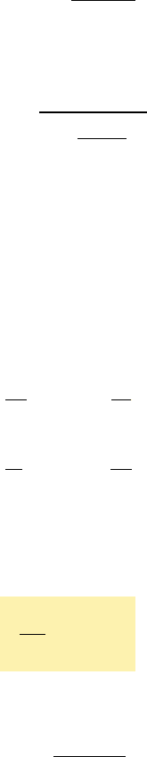
While a more detailed study of the transformations of strain
will be postponed until Chap. 7, we will derive in this section a
relation between the maximum shearing strain g9 5 g
m
associated
with the element of Fig. 2.49b and the normal strain P
x
in the direc-
tion of the load. Let us consider for this purpose the prismatic ele-
ment obtained by intersecting the cubic element of Fig. 2.49a by a
diagonal plane (Fig. 2.50a and b). Referring to Fig. 2.49a, we con-
clude that this new element will deform into the element shown in
Fig. 2.50c, which has horizontal and vertical sides respectively equal
to 1 1 P
x
and 1 2 nP
x
. But the angle formed by the oblique and
horizontal faces of the element of Fig. 2.50b is precisely half of one
of the right angles of the cubic element considered in Fig. 2.49b.
The angle b into which this angle deforms must therefore be equal
to half of py2 2 g
m
. We write
b 5
p
4
2
g
m
2
(b)
(a)
m
m
P
P'
P'
P
P
2A
z
x
y
'
45
x
x
P
A
P
2A
'
'
'
⫽
⫽
⫽
Fig. 1.38 (repeated )
1
1
1
11
x
1
x
4
1
(a)(b)(c)
Fig. 2.50
Applying the formula for the tangent of the difference of two angles,
we obtain
tan b 5
tan
p
4
2 tan
g
m
2
1 1 tan
p
4
tan
g
m
2
5
1 2 tan
g
m
2
1 1 tan
g
m
2
or, since g
m
y2 is a very small angle,
tan b 5
1 2
g
m
2
1 1
g
m
2
(2.39)
bee80288_ch02_052-139.indd Page 102 9/4/10 5:18:40 PM user-f499bee80288_ch02_052-139.indd Page 102 9/4/10 5:18:40 PM user-f499 /Users/user-f499/Desktop/Temp Work/Don't Delete Job/MHDQ251:Beer:201/ch02/Users/user-f499/Desktop/Temp Work/Don't Delete Job/MHDQ251:Beer:201/ch02
Apago PDF Enhancer
103
But, from Fig. 2.50c, we observe that
tan b 5
1 2 nP
x
1 1 P
x
(2.40)
Equating the right-hand members of (2.39) and (2.40), and solving
for g
m
, we write
g
m
5
11 1 n2P
x
1 1
1 2 n
2
P
x
Since P
x
V 1, the denominator in the expression obtained can be
assumed equal to one; we have, therefore,
g
m
5 (1 1 n)P
x
(2.41)
which is the desired relation between the maximum shearing strain
g
m
and the axial strain P
x
.
To obtain a relation among the constants E, n, and G, we recall
that, by Hooke’s law, g
m
5 t
m
yG, and that, for an axial loading, P
x
5
s
x
yE. Equation (2.41) can therefore be written as
t
m
G
5 11 1 n2
s
x
E
or
E
G
5 11 1 n2
s
x
t
m
(2.42)
We now recall from Fig. 1.38 that s
x
5 PyA and t
m
5 Py2A, where
A is the cross-sectional area of the member. It thus follows that
s
x
yt
m
5 2. Substituting this value into (2.42) and dividing both
members by 2, we obtain the relation
E
2
G
5 1 1 n
(2.43)
which can be used to determine one of the constants E, n, or G from
the other two. For example, solving Eq. (2.43) for G, we write
G 5
E
211 1 n2
(2.439)
*2.16 STRESS-STRAIN RELATIONSHIPS FOR
FIBER-REINFORCED COMPOSITE MATERIALS
Fiber-reinforced composite materials were briefly discussed in Sec.
2.5. It was shown at that time that these materials are obtained by
embedding fibers of a strong, stiff material into a weaker, softer mate-
rial, referred to as a matrix. It was also shown that the relationship
between the normal stress and the corresponding normal strain cre-
ated in a lamina, or layer, of a composite material depends upon the
direction in which the load is applied. Different moduli of elasticity,
E
x
, E
y
, and E
z
, are therefore required to describe the relationship
between normal stress and normal strain, according to whether the
*2.16 Stress-Strain Relationships for Fiber-
Reinforced Composite Materials
bee80288_ch02_052-139.indd Page 103 11/2/10 1:11:29 AM user-f499bee80288_ch02_052-139.indd Page 103 11/2/10 1:11:29 AM user-f499 /Users/user-f499/Desktop/Temp Work/Don't Delete Job/MHDQ251:Beer:201/ch02/Users/user-f499/Desktop/Temp Work/Don't Delete Job/MHDQ251:Beer:201/ch02
Apago PDF Enhancer
104
Stress and Strain—Axial Loading
load is applied in a direction parallel to the fibers, in a direction per-
pendicular to the layer, or in a transverse direction.
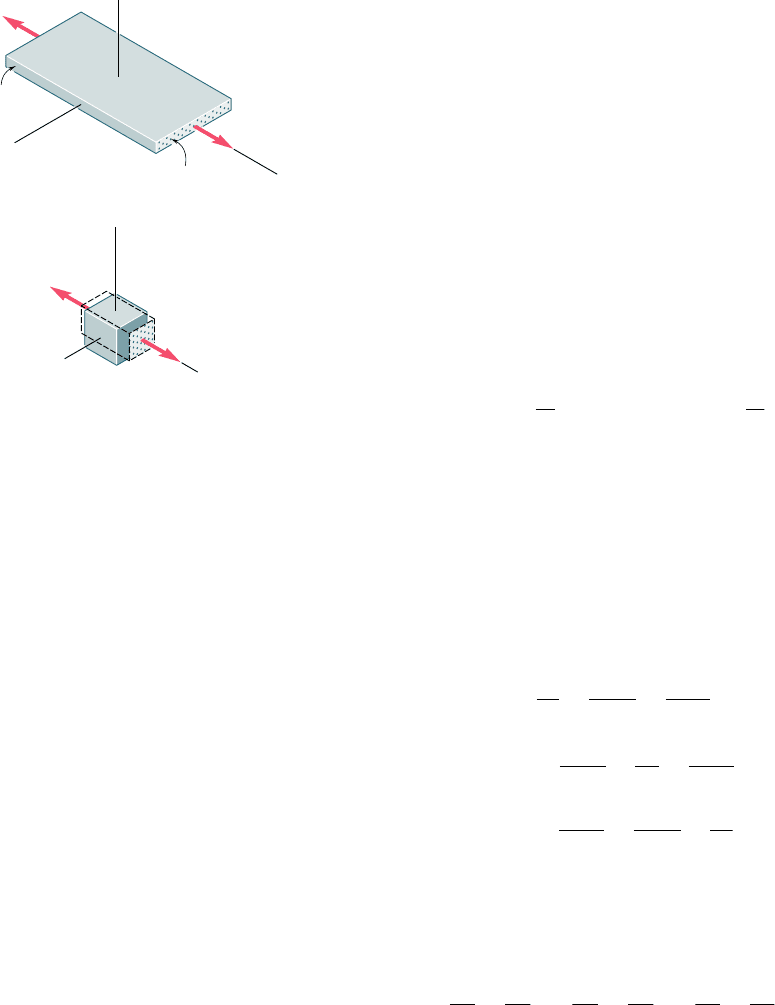
Let us consider again the layer of composite material discussed
in Sec. 2.5 and let us subject it to a uniaxial tensile load parallel to
its fibers, i.e., in the x direction (Fig. 2.51a). To simplify our analysis,
it will be assumed that the properties of the fibers and of the matrix
have been combined, or “smeared,” into a fictitious equivalent homo-
geneous material possessing these combined properties. We now con-
sider a small element of that layer of smeared material (Fig. 2.51b).
We denote by s
x
the corresponding normal stress and observe that
s
y
5 s
z
5 0. As indicated earlier in Sec. 2.5, the corresponding
normal strain in the x direction is P
x
5 s
x
yE
x
, where E
x
is the modulus
of elasticity of the composite material in the x direction. As we saw
for isotropic materials, the elongation of the material in the x direction
is accompanied by contractions in the y and z directions. These con-
tractions depend upon the placement of the fibers in the matrix and
will generally be different. It follows that the lateral strains P
y
and P
z
will also be different, and so will the corresponding Poisson’s ratios:
n
xy
52
P
y
P
x
and
n
xz
52
P
z
P
x
(2.44)
Note that the first subscript in each of the Poisson’s ratios n
xy
and
n
xz
in Eqs. (2.44) refers to the direction of the load, and the second
to the direction of the contraction.
It follows from the above that, in the case of the multiaxial load-
ing of a layer of a composite material, equations similar to Eqs. (2.28)
of Sec. 2.12 can be used to describe the stress-strain relationship. In
the present case, however, three different values of the modulus of
elasticity and six different values of Poisson’s ratio will be involved. We
write
P
x
5
s
x
E
x
2
n
yx
s
y
E
y
2
n
zx
s
z
E
z
P
y
52
n
xy
s
x
E
x
1
s
y
E
y
2
n
zy
s
z
E
z
(2.45)
P
z
52
n
xz
s
x
E
x
2
n
yz
s
y
E
y
1
s
z
E
z
Equations (2.45) may be considered as defining the transformation
of stress into strain for the given layer. It follows from a general
property of such transformations that the coefficients of the stress
components are symmetric, i.e., that
n
xy
E
x
5
n
yx
E
y
n
yz
E
y
5
n
zy
E
z
n
zx
E
z
5
n
xz
E
x
(2.46)
These equations show that, while different, the Poisson’s ratios n
xy
and n
yx
are not independent; either of them can be obtained from
the other if the corresponding values of the modulus of elasticity are
known. The same is true of n
yz
and n
zy
, and of n
zx
and n
xz
.
Consider now the effect of the presence of shearing stresses
on the faces of a small element of smeared layer. As pointed out in
Layer of
material
Fibers
Load
Load
y
z
x
(a)
Fig. 2.51 Fiber-reinforced composite
material under uniaxial tensile load.
y'
z'
x
x
'
(b)
x
bee80288_ch02_052-139.indd Page 104 11/8/10 8:07:43 PM user-f499bee80288_ch02_052-139.indd Page 104 11/8/10 8:07:43 PM user-f499 /Users/user-f499/Desktop/Temp Work/Don't Delete Job/MHDQ251:Beer:201/ch02/Users/user-f499/Desktop/Temp Work/Don't Delete Job/MHDQ251:Beer:201/ch02
Apago PDF Enhancer
105
Sec. 2.14 in the case of isotropic materials, these stresses come in pairs
of equal and opposite vectors applied to opposite sides of the given
element and have no effect on the normal strains. Thus, Eqs. (2.45)
remain valid. The shearing stresses, however, will create shearing
strains which are defined by equations similar to the last three of the
equations (2.38) of Sec. 2.14, except that three different values of the
modulus of rigidity, G
xy
, G
yz
, and G
zx
, must now be used. We have
g
xy
5
t
xy
G
x
y
g
yz
5
t
yz
G
y
z
g
zx
5
t
zx
G
zx
(2.47)
The fact that the three components of strain P
x
, P
y
, and P
z
can
be expressed in terms of the normal stresses only and do not depend
upon any shearing stresses characterizes orthotropic materials and
distinguishes them from other anisotropic materials.
As we saw in Sec. 2.5, a flat laminate is obtained by superposing
a number of layers or laminas. If the fibers in all layers are given the
same orientation to better withstand an axial tensile load, the lami-
nate itself will be orthotropic. If the lateral stability of the laminate
is increased by positioning some of its layers so that their fibers are
at a right angle to the fibers of the other layers, the resulting laminate
will also be orthotropic. On the other hand, if any of the layers of a
laminate are positioned so that their fibers are neither parallel nor
perpendicular to the fibers of other layers, the lamina, generally, will
not be orthotropic.†
†For more information on fiber-reinforced composite materials, see Hyer, M. W., Stress
Analysis of Fiber-Reinforced Composite Materials, McGraw-Hill, New York, 1998.
2.16 Stress-Strain Relationships for Fiber-
Reinforced Composite Materials
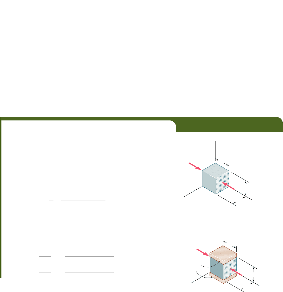
EXAMPLE 2.11
A 60-mm cube is made from layers of graphite epoxy with fibers aligned
in the x direction. The cube is subjected to a compressive load of 140 kN
in the x direction. The properties of the composite material are: E
x
5
155.0 GPa, E
y
5 12.10 GPa, E
z
5 12.10 GPa, n
xy
5 0.248, n
xz
5 0.248,
and n
yz
5 0.458. Determine the changes in the cube dimensions, knowing
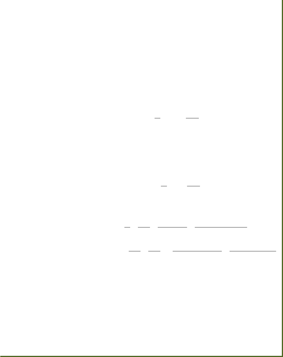
that (a) the cube is free to expand in the y and z directions (Fig. 2.52);
(b) the cube is free to expand in the z direction, but is restrained from
expanding in the y direction by two fixed frictionless plates (Fig. 2.53).
(a) Free in y and z Directions. We first determine the stress s
x
in the direction of loading. We have
s
x
5
P
A
5
2140 3 10
3
N
1
0.060 m
21
0.060 m
2
5238.89 MPa
Since the cube is not loaded or restrained in the y and z directions, we have
s
y
5 s
z
5 0. Thus, the right-hand members of Eqs. (2.45) reduce to their
first terms. Substituting the given data into these equations, we write
P
x
5
s
x
E
x
5
2
38
.
89
MPa
155.0 GPa
52250.9 3 10
26
P
y
52
n
xy
s
x
E
x
52
1
0.248
21
238.89 MPa
2
155.0 GPa
5162.22 3 10
26
P
z
52
n
xz
s
x
E
x
52
1
0.248
21
238.69 MPa
2
155.0 GPa
5162.22 3 10
26
y
z
140 kN
60 mm
60 mm
60 mm
140 kN
x
Fig. 2.52
y
z
140 kN
60 mm
60 mm
Fixed
frictionless
plates
60 mm
140 kN
x
Fig. 2.53
bee80288_ch02_052-139.indd Page 105 11/8/10 9:37:51 PM user-f494bee80288_ch02_052-139.indd Page 105 11/8/10 9:37:51 PM user-f494 volume 201/FREE048/work%0/indd%0/volume 201/FREE048/work%0/indd%0/
Apago PDF Enhancer
The changes in the cube dimensions are obtained by multiplying the cor-
responding strains by the length L 5 0.060 m of the side of the cube:
d
x
5 P
x
L 5
1
2250.9 3 10
2
6
21
0.060 m
2
5215.05 mm
d
y
5 P
y
L 5 1162.2 3 10
2
6
210.060 m2513.73 mm
d
z
5 P
z
L 5
1
162.2 3 10
2
6
21
0.060 m
2
513.73 mm
(b) Free in z Direction, Restrained in y Direction. The stress
in the x direction is the same as in part a, namely, s
x
5 238.89 MPa.
Since the cube is free to expand in the z direction as in part a, we again
have s
z
5 0. But since the cube is now restrained in the y direction,
we should expect a stress s
y
different from zero. On the other hand,
since the cube cannot expand in the y direction, we must have d
y
5 0
and, thus, P
y
5 d
y
yL 5 0. Making s
z
5 0 and P
y
5 0 in the second of
Eqs. (2.45), solving that equation for s
y
, and substituting the given data,
we have
s
y
5 a
E
y
E
x
b n
xy
s
x
5 a
12.10
155.0
b10.24821238.89 MPa2
52752
.
9
k
P
a
Now that the three components of stress have been determined, we can
use the first and last of Eqs. (2.45) to compute the strain components
P
x
and P
z
. But the first of these equations contains Poisson’s ratio n
yx
and, as we saw earlier, this ratio is not equal to the ratio n
xy
which was
among the given data. To find n
yx
we use the first of Eqs. (2.46) and
write
n
yx
5 a
E
y
E
x
b n
xy
5 a
12.10
155.0
b10.24825 0.01936
Making s
z
5 0 in the first and third of Eqs. (2.45) and substituting in
these equations the given values of E
x
, E
y
, n
xz
, and n
yz
, as well as the values
obtained for s
x
, s
y
, and n
yx
, we have
P
x
5
s
x
E
x
2
n
yx
s
y
E
y
5
238.89 MPa
155.0 GPa
2
1
0.01936
21
2752.9 kPa
2
12.10 GPa
52249
.
7 3 10
2
6
P
z
52
n
xz
s
x
E
x
2
n
yz
s
y
E
y
52
1
0.248
21
238.89 MPa
2
155.0 GPa
2
1
0.458
21
2752.9 kPa
2
12.10 GPa
5190
.
72 3 10
2
6
The changes in the cube dimensions are obtained by multiplying the cor-
responding strains by the length L 5 0.060 m of the side of the cube:
d
x
5 P
x
L 5
1
2249.7 3 10
2
6
21
0.060 m
2
5214.98 mm
d
y
5 P
y
L 5
1
0
21
0.060 m
2
5 0
d
z
5 P
z
L 5
1
190.72 3 10
2
6
21
0.060 m
2
515.44 mm
Comparing the results of parts a and b, we note that the difference
between the values obtained for the deformation d
x
in the direction of
the fibers is negligible. However, the difference between the values
obtained for the lateral deformation d
z
is not negligible. This deformation
is clearly larger when the cube is restrained from deforming in the y
direction.
106
bee80288_ch02_052-139.indd Page 106 11/2/10 1:11:30 AM user-f499bee80288_ch02_052-139.indd Page 106 11/2/10 1:11:30 AM user-f499 /Users/user-f499/Desktop/Temp Work/Don't Delete Job/MHDQ251:Beer:201/ch02/Users/user-f499/Desktop/Temp Work/Don't Delete Job/MHDQ251:Beer:201/ch02