Basdevant J.-L., Rich J., Spiro M. Fundamentals in Nuclear Physics: From Nuclear Structure to Cosmology
Подождите немного. Документ загружается.

B. Accelerators
The scattering experiments discussed in Chap. 3 generally required the use
of beams of charged particles produced by accelerators. A notable exception
is the original Rutherford-scattering experiments that used α-particles from
natural radioactive decays. Neutron-scattering experiments use neutrons pro-
duced at fission reactors or secondary neutrons produced by the scattering
of accelerated charged particles.
Particle accelerators require a source of charged particles and an elec-
tric field to accelerate them. They can be classified as DC machines using
static electric fields and AC machines using oscillating fields. The second cat-
egory can be divided into linear accelerators where particles are accelerated
in straight line and magnetic accelerators, i.e. cyclotrons and synchrotrons,
where particles move in circular orbits.
ion
source
charging belt
evacuated beam tube
+++++++++++++
hollow
conductor
HV charger
beam
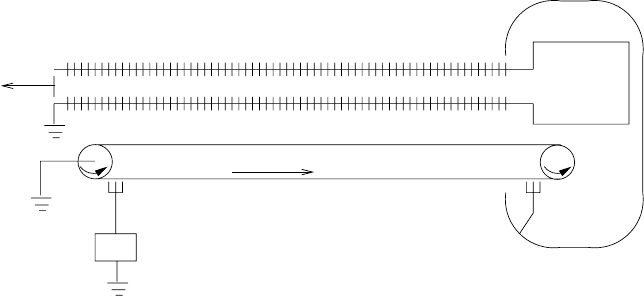
Fig. B.1. A schematic of a simple Van de Graff accelerator. Positive charges are
transfered from ground potential to a hollow terminal. The ion source is placed
inside the terminal and particles are accelerated through the electrostatic field to
ground potential.
In simple electrostatic systems, an ion source is placed at high voltage
and extracted ions are accelerated through the electric field. Potentials of
1 − 2 MV can be produced with normal rectifier circuits and potentials up
446 B. Accelerators
to 10 MV can be produced in a Van de Graff accelerator, illustrated in Fig.
B.1. In this system, charge is transformed to the positive terminal by an
insulating belt. Ions are accelerated through an evacuated tube constructed
from alternating insulators and electrodes so as to maintain a constant gra-
dient. The maximum potential is limited by breakdown in the surrounding
gas. Currents in the mA range can be achieved.
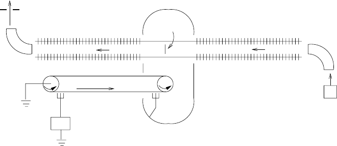
Tandem Van de Graff Accelerators (Fig. B.2) modify the basic design to
provide higher energy and an ion source that is at ground potential, making
it more accessible. In this case, the source provides singly-charged negative
ions, e.g. O
−
containing an extra electron. These are accelerating to the
positive terminal where a “stripper” consisting of a thin foil or gas-containing
tubes removes electrons. The resulting positive ions are then accelerated to
ground potential where an analyzing magnet selects a particular value of
q/m. Obtainable currents are in the µA range, smaller than simple Van de
Graffs because of the difficulty in obtaining negative ions.
beam
+++++
HV
stripper
source
negative−ion
+
+
+
__
magnet
slit
Fig. B.2. A schematic of a tandem Van de Graff accelerator. Negative ions are
accelerated to the positive potential where a “stripper” removes electrons. The
resulting positive ions are then accelerating to ground potential where a definite
charge state is selected by a magnetic field and slit.
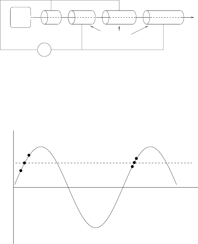
The 10 MV limitation of DC machines can be avoided by using radio-
frequency (RF) electric fields. The frequency is typically ∼ 30 MHz. The sim-
plest configuration is the linear accelerator, or linac, illustrated in Fig. B.3.
The RF voltage is applied to alternating conducting “drift tubes” so that
charged particles are accelerating between tubes if they arrive at the gaps
at appropriate times. The tube lengths must thus decrease in length as the
particle velocity increases down the accelerator. Linacs produce a “bunched”
beam consisting of pulses of particles. The bunch structure is persists during
the acceleration because of the “phase stability” illustrated in Fig. B.4.
B. Accelerators 447
rf supply
~
ion source
beam
pulse
d
drift tubes
Fig. B.3. A schematic of a drift-tube linear accelerator. Ions are accelerated in the
alternating electric field between drift-tubes.
Linear accelerators are most commonly used to accelerate electrons. The
largest is the 2-mile long accelerating SLAC at Stanford, California, that
produces 20 GeV electrons.
accelerating voltage
time
a
b
c
b’
optimu
m
voltage
a’
c’
Fig. B.4. The principle of phase stability in a linear accelerator. Particles arriving
in a gap at point b are accelerated such that they arrive at the text gap at the point
b’ with the same phase with respect to the alternating field. Particles arriving at
point a (c) receive more (less) acceleration and therefore arrive relatively earlier
(later) in the next gap, point a’ (c’). Particles in the range a-c are thus “focused”
in phase-space toward the point b.
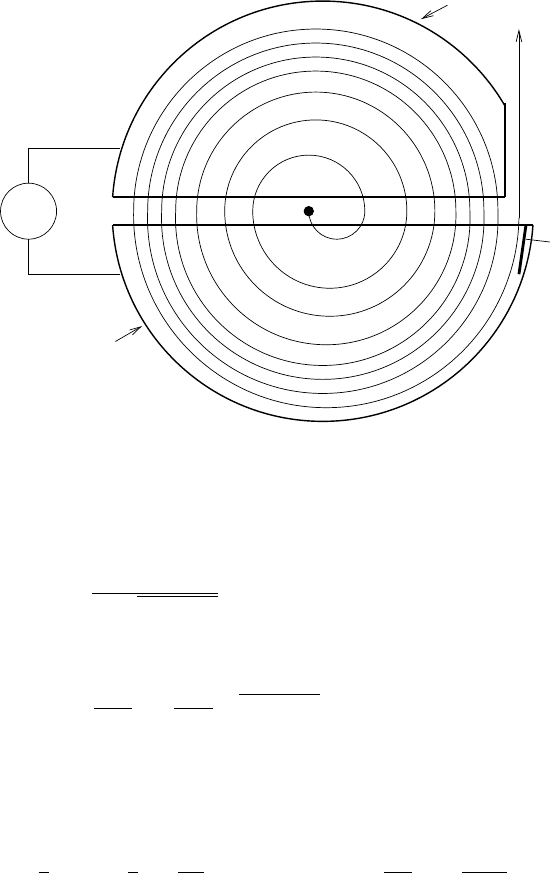
Cyclotrons are a common class of accelerators illustrated in Fig. B.5. Ion
orbit in a dipole magnetic field where they are accelerated twice per orbit
in a RF field. As they are accelerated, the ions spiral out with the radius of
curvature given by
448 B. Accelerators
~
beam
deflecto
r
rf supply
Dee
magnetic field
(into page)
D
ee
Fig. B.5. Schematic of a cyclotron. Particles are injected near the center of a
dipole magnetic field and then spiral outward as they gain energy each time they
pass through the alternating electric field between two electrodes called “Dee’s.”
The radio-frequency is tuned to the particle’s cyclotron frequency, ω
c
= qB/m.
Near the maximum radius, the particles are deflected out of the cyclotron.
R =
mv
qB
1 − v
2
/c
2
, (B.1)
for a particle of velocity v,massm and charge q. The orbital frequency is
then
f
c
=
v
2πR
=
qB
2πm
1 − v
2
/c
2
, (B.2)
and the RF must be tuned to this frequency to accelerate the particles.
As long as the particle remains non-relativistic, v c, the frequency
is a constant, proportional to the cyclotron frequency, qB/m,equalto
9.578 × 10
7
rad s
−1
T
−1
× B. The energy at radius R is, for v c
1
2
mv
2
=
1
2
m
qB
m
2
R
2
∼ 10 MeV
B
1T
2
R
0.5m
2
, (B.3)
where the numerical example is for a proton. A modest-sized cyclotron can
therefore produce particles of energies interesting for nuclear-physics experi-
ments. Currents in the mA range can be produced.
The simple design of a constant-field cyclotron must be modified in prac-
tical designs for a number of reasons. Most important is the necessity to
prevent the particles from spiraling in the vertical direction. This can be pre-
vented by introducing a small radial variation of the field, as illustrated in
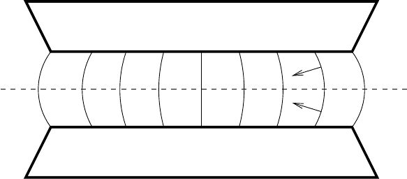
B. Accelerators 449
Fig. B.6. This introduces vertical components to the force on particles that
are not in the median plane so that particles are focused in the vertical di-
rection. Unfortunately, this simple scheme introduces other problems, among
them being that the required RF frequency now depends on position. More
popular focusing schemes use magnetic fields that vary azimuthally to obtain
the desired effect.
For energies > 1 GeV, cyclotrons become impractical because of the large
required radius. It then becomes more practical to use synchrotron’s where
ring of dipole magnets replace the one large dipole. The accelerating force is
provided by RF cavities distributed about the ring in spaces between mag-
nets. Vertical and horizontal focusing is provided by quadrupole magnets.
Sychrotrons are the most common accelerators in the field of high-energy
particle physics.
media
n
plane
north
south
Fig. B.6. Vertical focusing in a radially-decreasing dipole magnetic field. Particles
in the median plane experience a horizontal force. The force on particles above or
below the median plane has a vertical component that pushes the particle back
toward the median.

C. Time-dependent perturbation theory
Perturbation theory is the basis for most of the calculations performed in
Chaps3and4.Herewederivethebasicequations.
C.0.1 Transition rates between two states
Consider a system described by a Hamiltonian H that is the sum of a “non-
perturbed” Hamiltonian H
0
and a small perturbation H
1
which can induce
transitions between various eigenstates of H
0
. It is useful to express the state
of the system as a superposition of eigenstates of H
0
:
|ψ(t) =
i
γ
i
(t)e
−iE
i
t/¯h
|i , (C.1)
where
H
0
|i = E
i
|i . (C.2)
We suppose that the system is initially in the state |i:
γ
i
(t =0) = 1 γ
j=i
(0) = 0 . (C.3)
At a later time, it has an amplitude γ
f
(t) to be in some other state |f.This
amplitude can be calculated using the Schr¨odinger equation
i¯h
d
dt
|ψ(t) =(H
0
+ H
1
)|ψ(t) . (C.4)
Substituting (C.1) into this equation, multiplying on the left by f| and using
i|j = δ
ij
, we find a differential equation for γ
f
(t):
i¯h
dγ
f
(t)
dt
=
k
γ
k
(t)f|H
1
|ke
i(E
f
−E
k
)t
. (C.5)
This equation is exact but can only be solved numerically. A perturbative
solution for small t is found by using (C.3) to use the first approximation
γ
i
(t)=1:
i¯h
dγ
f
(t)
dt
= f |H
1
|ie
i(E
f
−E
i
)t
. (C.6)
This equation can be directly integrated to give the first order time-dependent
perturbation theory estimate of γ
f
:

452 C. Time-dependent perturbation theory
γ
1
f
(t)=
−2i
π
e
i(E
f
−E
i
)t/2¯h
f|H
1
|i ∆
t
(E
f
− E
i
) . (C.7)
In this expression we have introduced a limiting form of the Dirac distribution
∆
t
(E
f
− E
i
)=
1
π
sin(E
f
− E
i
)t/2¯h)
E
f
− E
i
(C.8)
which we discuss below.
Squaring this amplitude, we find the probability that the system is in the
state f at time t
P
if
(t)=
2πt
¯h
|f|H
1
|i|
2
δ
t
(E
f
− E
i
) , (C.9)
where δ
t
(E), which we will discuss below, is a function that is peaked at
E = 0 with a width ∆E ∼ ¯h/t:
δ
t
(E)=
1
π
sin
2
(Et/2¯h)
E
2
t/2¯h
. (C.10)
In the limit t →∞δ
t
approaches the Dirac delta function:
∞
−∞
δ
t
(E)dE =1. (C.11)
This means that at large time [t(E
f
−E
i
))/¯h 1] the only states that are
populated are those that conserve energy to within the Heisenberg condition
∆E t > ¯h.
If for some reason the first-order probability vanishes, second-order per-
turbation theory gives
P
if
(t)=
2πt
¯h
j=i,f
f|H
1
|jj|H
1
|i
E
j
− E
i
2
δ
t
(E
f
− E
i
) . (C.12)
The transition rate is found by simply dividing the probability by the
time t:
λ
if
=
P
if
(t)
t
(C.13)
Total transition rates are found by summing (C.13) over all final states
f.
λ =
f
P
if
(t)
t
=
2π
¯h
f
|f|H
1
|i|
2
δ
t
(E
f
− E
i
) . (C.14)
If the states f form a continuum with ρ
f
(E)dE states within the energy
interval dE and if all these states have the same matrix element, we can
simply replace the sum by an integral and find the Fermi golden rule:
λ =
2π
¯h
|f|H
1
|i|
2
ρ
f
(E
i
) . (C.15)

C. Time-dependent perturbation theory 453
C.0.2 Limiting forms of the delta function
In the above expressions, it has been useful to introduce the functions :
∆
T
(E)=
1
π
sin(ET/2¯h)
E
(C.16)
and
δ
T
(E)=
1
π
sin
2
(ET/2¯h)
E
2
T/2¯h
. (C.17)
We note that
∞
−∞
∆
T
(E)=1 , (C.18)
and
∞
−∞
δ
t
(E)=1 . (C.19)
In the limit T →∞, these two functions tend, in the sense of distributions,
to the Dirac distribution
lim
T →∞
∆
T
(E) = lim
T →∞
δ
T
(E)=δ(E) . (C.20)
They are related by :
(∆
T
(E))
2
=
T
2π¯h
δ
T
(E) , ∀T. (C.21)
The generalization to three variables is straightforward:
∆
3
L
(p)=
3
i=1
∆
L
(p
i
) ,δ
3
L
(p)=
3
i=1
δ
L
(p
i
) , (C.22)
with p =(p
1
,p
2
,p
3
). We have quite obviously
lim
L→∞
∆
3
L
(p) = lim
L→∞
δ
3
L
(p)=δ
3
(p) , (C.23)
and
(∆
3
L
(p))
2
=
L
3
(2π¯h)
3
δ
3
L
(p) ∀L. (C.24)

D. Neutron transport
In this appendix, we give a few more details about neutron transport in mat-
ter and the Boltzmann equation used in Sect. 6.7. We refer to the literature
1
for more complete details.
D.0.3 The Boltzmann transport equation
The Boltzmann transport equation governs the behavior of neutrons in mat-
ter. We shall write it under the following assumptions:
• The medium is static (neglecting small thermal motions); it is, spherical,
homogeneous, and consists of
239
Pu nuclei.
• Neutron–neutron scattering is negligible (since the density of neutrons is
much smaller than the density of the medium) ;
• Neutron decay is negligible, i.e. the neutron lifetime is very large compared
to the typical time differences between two interactions.
The neutrons are described by their density in phase space
dN
d
3
pd
3
r
= f (r, p,t) , (D.1)
where dN is the number of neutrons in the phase space element d
3
pd
3
r.
The space density of neutrons and the current describing the spatial flow of
neutrons are the integrals over the momentum
n(r,t)=
f(r, p,t)d
3
p ,
J(r,t)=
vf(r, p,t)d
3
p .
In the absence of collisions, neutron momenta are time-independent and
the flow of particles in phase space is generated by the motion of particle at
velocities v = p/m. The density f satisfies an equation of the form
1
See for instance, E. M. Lifshitz and L. P. Pitaevskii Physical Kinetics, Pergamon
Press, 1981; C. Cercignani, Theory and application of the Boltzmann Equation,
Scottish Academic Press, 1975.

456 D. Neutron transport
∂f
∂t
+ v · ∇f = C(f) , (D.2)
where C(f) is the term arising from collision processes, for which we will find
an explicit form shortly. For C(f) = 0, (D.2) is called the Liouville equation.
The elastic scattering and absorption rates λ
el
and λ
abs
are products of
the elementary cross-sections, the density of scattering centers n
239
,andthe
mean velocity v
λ
el
= vn
239
σ
el
λ
abs
= vn
239
σ
abs
(D.3)
The absorption is due to both (n, γ) reactions and to fission
σ
abs
= σ
(n,γ)
+ σ
fis
. (D.4)
The collision term is then written as
C(f (p)) = n
239
d
3
p
v(p
) f(r, p
,t)
dσ
d
3
p
(p
→ p) (D.5)
−[λ
el
+ λ
abs
]f(r, p,t)+S(r, p) .
The first term accounts for neutrons coming from the elements of phase space
d
3
rd
3
p
which enter the element of phase space d
3
rd
3
p by elastic scattering.
The second term represents the neutrons which leave the element d
3
rd
3
p
either by elastic scattering or by absorption. The last term S(r, p) is a source
term, representing the production of neutrons by fission.
D.0.4 The Lorentz equation
We recall that we assume the neutrons all have the same time-independent
energy, and that the medium is homogeneous.
In that case, the differential elastic scattering cross-section is
dσ
d
3
p
(p → p
)=p
−2
δ(p − p
)
dσ
dΩ
. (D.6)
We also assume, for simplicity, that the scattering cross section is isotropic
dσ
el
dΩ
=
σ
el
4π
. (D.7)
Later on, we will also make the assumption that all neutrons have the same
velocity, v, i.e. that the function f(r, p) is strongly peaked near values of
momentum satisfying |p| = m
n
v.
Using (D.7) we find that the Boltzmann equation (D.2) and (D.5) reduces
to the Lorentz equation
∂f
∂t
+ v · ∇f = λ
el
(
¯
f − f ) − λ
abs
f + S(r, p) , (D.8)
where
