ASME Section VIII div 2 2010. ASME Boiler and Pressure Vessel Code. Alternative Rules
Подождите немного. Документ загружается.


2010 SECTION VIII-2
7-27
Table 7.5 – NDE Techniques, Method, Characterization, Acceptance Criteria
NDT Technique Method
Paragraph Reference For
Characterization And Acceptance
Criteria
Visual Examination (VT) --- 7.5.2
Radiographic Examination (RT) Section V Article 2 7.5.3
Ultrasonic Examination(UT) Section V Article 4 7.5.4
Ultrasonic Examination (when used in
lieu of RT)
Section V Article 4 and
paragraph 7.5.5
7.5.5
Magnetic Particle Examination (MT) Section V Article 7 7.5.6
Liquid Penetrant Examination (PT) Section V Article 6 7.5.7
Eddy Current Examination (ET) Paragraph 7.5.8 7.5.8
2010 SECTION VIII-2
7-28
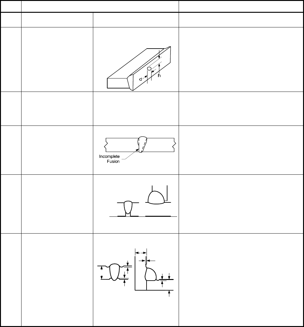
Table 7.6 – Visual Examination Acceptance Criteria
No. Type Of Imperfection
1
Acceptance Criteria
1
Cracks (all) --- Not permitted.
2 Gas cavity (all)
Shrinkage cavity (all)
Not Permitted
3 Slag inclusions (all)
Flux inclusions (all)
Oxide inclusions (all)
Metallic inclusions (all)
---
Not permitted when occurring at the
surface
2
.
4 Incomplete fusion (all)
Not permitted.
5 Lack of penetration
Not permitted if a complete penetration
weld is required
6 Undercut
h
h
t
t
t2
h2
h1
Refer to paragraph 6.2.4.1 (b)(2) for
acceptable undercut
Requirements in paragraph 7.5.3.2 to
permit proper interpretation of radiography
shall also be satisfied.
标准分享网 www.bzfxw.com 免费下载

2010 SECTION VIII-2
7-29
Table 7.6 – Visual Examination Acceptance Criteria
No. Type Of Imperfection
1
Acceptance Criteria
7 Weld reinforcement Acceptable weld reinforcement in butt
welding joints shall be in accordance with
paragraph 6.2.4.1.d. A smooth transition
is required.
8 Joint offset
---
Refer to paragraph 6.1.6 for acceptable
offset in butt welded joints.
9 Peaking
---
Refer to paragraph 6.1.6 for acceptable
peaking in butt welding joints.
10 Stray flash or arc strike --- Not permitted
2
.
11 Spatter --- Spatter shall be minimized
2
.
12 Torn surface
Grinding mark
Chipping mark
---
Not permitted
2
.
13 Concavity
h
t
Refer to paragraph 6.2.4.1(d) for
acceptable concavity
Notes:
1) The following symbols are used in this table.
a – nominal fillet weld throat thickness
b – width of weld reinforcement
d – diameter of pore
h – height of imperfections
t – wall or plate thickness
2) These imperfections may be removed by blend grinding.

2010 SECTION VIII-2
7-30
Table 7.7 – Radiographic Acceptance Standards For Rounded Indications (Examples Only)
Thickness - t
Maximum Size of Acceptable Rounded Indication
Maximum Size of Non-
relevant Indications
Random Isolated
Less than 3 mm (1/8 in) 1/4 t 1/3 t 1/10 t
3 mm (1/8 in)
0.8 mm (1/32 in) 1.1 mm (3/64 in) 0.4 mm (1/64 in)
5 mm (3/16 in)
1.2 mm (3/64 in) 1.5 mm (1/16 in) 0.4 mm (1/64 in)
6 mm (1/4 in)
1.5 mm (1/16 in) 2.1 mm (3/32 in) 0.4 mm (1/64 in)
8 mm (5/16 in) 2.0 mm (5/64 in) 2.6 mm (7/64 in) 0.8 mm (1/32 in)
10 mm (3/8 in) 2.5 mm (3/32 in) 3 mm (1/8 in) 0.8 mm (1/32 in)
11 mm (7/16 in) 2.8 mm (7/64 in) 3.7 mm (5/32 in) 0.8 mm (1/32 in)
13 mm (1/2 in)
3 mm (1/8 in) 4.3 mm (11/64 in) 0.8 mm (1/32 in)
14 mm (9/16 in)
3.6 mm (5/64 in) 5 mm (3/16in.) 0.8 mm (1/32 in)
16 mm (5/8 in)
4.0 mm (5/32 in) 5.3 mm (7/32 in) 0.8 mm (1/32 in)
17 mm (11/16 in)
4.0 mm (5/32 in) 5.8 mm (15.64 in) 0.8 mm (1/32 in)
19 mm (3/4 in) to
50 mm (2 in), inclusive
4.0 mm (5/32 in) 6.4 mm (1/4 in) 0.8 mm (1/32 in)
Over 50 mm (2 in)
4.0 mm (5/32 in) 10 mm (3/8 in) 1.5 mm (1/16 in)
标准分享网 www.bzfxw.com 免费下载
2010 SECTION VIII-2
7-31
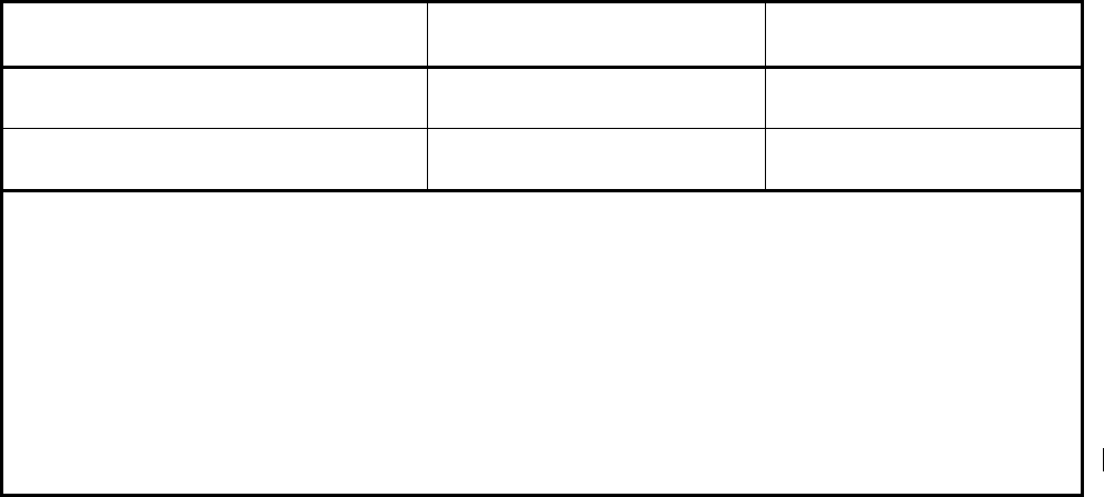
Table 7.8 – Flaw Acceptance Criteria For Welds With A Thickness Between 13 mm (1/2 in.) And Less
Than 25 mm (1 in)
Flaw Type
/at
l
Surface flaw
≤
0.087 ≤ 6.4 mm ( 1/4 in)
Subsurface flaw
≤
0.143 ≤ 6.4 mm ( 1/4 in)
Notes:
1) The parameter t is the thickness of the weld excluding any allowable reinforcement, and the parameter
l is the length of the flaw. For a butt weld joining two members having different thickness at the weld, t
is the thinner of these two thicknesses. If a full penetration weld includes a fillet weld, then the thickness
of the throat of the fillet weld shall be included in
t .
2) A subsurface indication shall be considered as a surface flaw if the separation (
S in Figure 7.11) of the
indication from the nearest surface of the component is equal to or less than half the through dimension
(2d in Figure 7.11, Sketch (b)) of the subsurface indication.
3) The acceptance limits specified here are based upon workmanship considerations and are not
necessarily intended for use in evaluating flaws identified after the vessel has gone into service.
4) a and l are as defined in paragraph 7.5.5.2.
2010 SECTION VIII-2
7-32
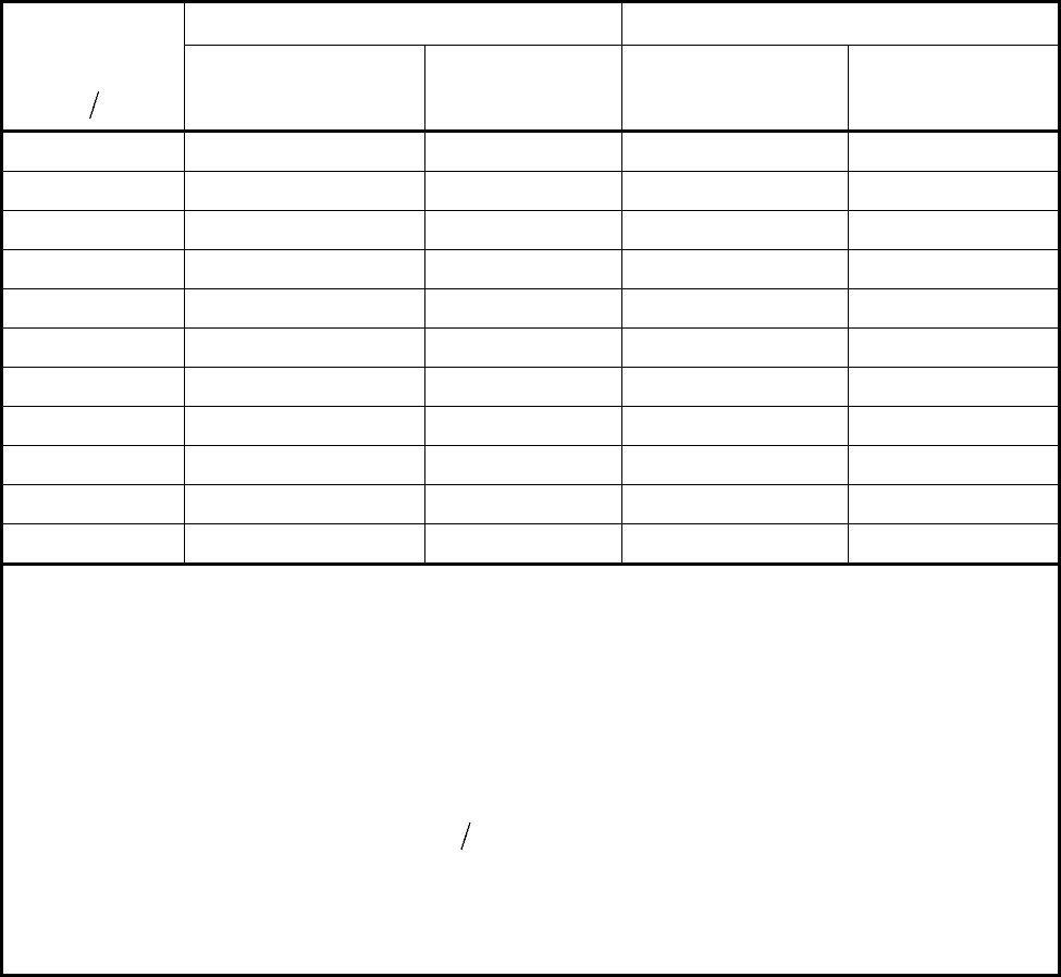
Table 7.9 – Flaw Acceptance Criteria For Welds With Thickness Between 25 mm ( 1 in) And Less
Than or Equal to 300 mm (12 in)
Flaw
Aspect Ratio
al
25 mm (1 in)
t≤<
64 mm (2 1/2in) 100 mm (4 in)
t
≤
≤
300 mm (12 in)
Surface Flaw
/at
Subsurface Flaw
/at
Surface Flaw
/at
Subsurface Flaw
/at
0.00 0.031 0.034 0.019 0.020
0.05 0.033 0.038 0.020 0.022
0.10 0.036 0.043 0.022 0.025
0.15 0.041 0.049 0.025 0.029
0.20 0.047 0.057 0.028 0.033
0.25 0.055 0.066 0.033 0.038
0.30 0.064 0.078 0.038 0.044
0.35 0.074 0.090 0.044 0.051
0.40 0.083 0.105 0.050 0.058
0.45 0.085 0.123 0.051 0.067
0.50 0.087 0.143 0.052 0.076
Notes:
1) The parameter t is the thickness of the weld excluding any allowable reinforcement, and the parameter
l is the length of the flaw. For a butt weld joining two members having different thickness at the weld, t
is the thinner of these two thicknesses. If a full penetration weld includes a fillet weld, then the thickness
of the throat of the fillet weld shall be included in
t .
2) A subsurface indication shall be considered as a surface flaw if the separation (
S in Figure 7.11) of the
indication from the nearest surface of the component is equal to or less than half the through dimension
(2d in Figure 7.11, Sketch (b)) of the subsurface indication.
3) The acceptance limits specified here are based upon workmanship considerations and are not
necessarily intended for use in evaluating flaws identified after the vessel has gone into service.
4) For intermediate flaw aspect ratio
aland thickness t (64 mm [2 ½ in.] < t < 100 mm [4 in.]), linear
interpolation is permissible.
5) If the acceptance criteria in this table results in a flaw length, l , less than 6.4 mm (0.25 in.), a value of
6.4mm (0.25 in.) may be used.
6) For materials exceeding 655 MPa (95 ksi) ultimate tensile strength, the use of this table is limited to a
thickness of 200 mm (8 in.).
标准分享网 www.bzfxw.com 免费下载
2010 SECTION VIII-2
7-33
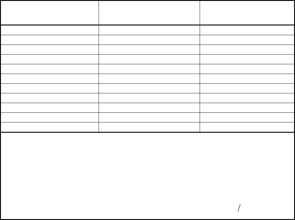
Table 7.10 – Flaw Acceptance Criteria For Welds With A Thickness Greater Than 300 mm (12 in)
Aspect Ratio
/al
Surface Flaw
a
Subsurface Flaw
a
0.00 5.8 mm (0.228 in) 6.1 mm (0.240 in)
0.05 6.1 mm (0.240 in) 6.7 mm (0.264 in)
0.10 6.7 mm (0.264 in) 7.6 mm (0.300 in)
0.15 7.6 mm (0.300 in) 8.8 mm (0.348 in)
0.20 8.5 mm (0.336 in) 10.1 mm (0.396 in)
0.25 10.1 mm (0.396 in) 11.6 mm (0.456 in)
0.30 11.6 mm (0.456 in) 13.4 mm (0.528 in)
0.35 13.4 mm (0.528 in) 15.5 mm (0.612 in)
0.40 15.2 mm (0.600 in) 17.7 mm (0.696 in)
0.45 15.5 mm (0.612 in) 20.4 mm (0.804 in)
0.50 15.8 mm (0.624 in) 23.2 mm (0.912 in)
Notes:
1) The parameter t is the thickness of the weld excluding any allowable reinforcement, and the parameter
l is the length of the flaw. For a butt weld joining two members having different thickness at the weld, t
is the thinner of these two thicknesses. If a full penetration weld includes a fillet weld, then the thickness
of the throat of the fillet weld shall be included in t .
2) A subsurface indication shall be considered as a surface flaw if the separation (
S in Figure 7.11) of the
indication from the nearest surface of the component is equal to or less than half the through dimension
(2d in Figure 7.11, Sketch (b)) of the subsurface indication.
3) The acceptance limits specified here are based upon workmanship considerations and are not
necessarily intended for use in evaluating flaws identified after the vessel has gone into service.
4) Linear interpolation is permissible for intermediate values of the flaw aspect ratio
al
.
5) This table is not applicable for materials exceeding 655 MPa (95 ksi) ultimate tensile strength.
2010 SECTION VIII-2
7-34
7.10 Figures
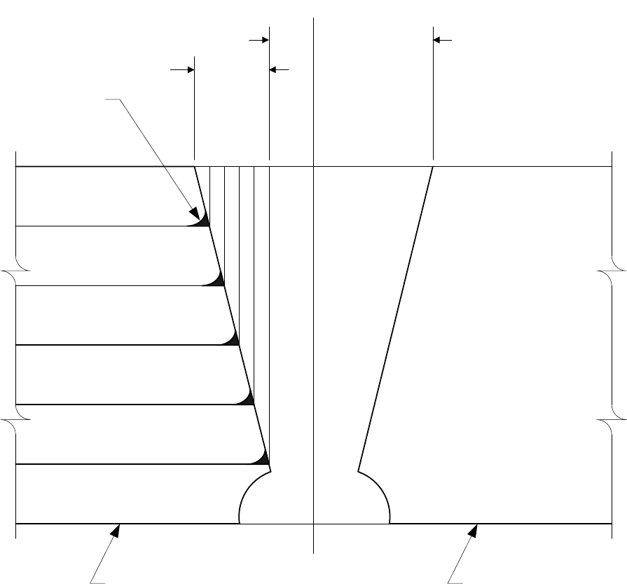
Not judged
Judged
Any indication not in
line with layer
interface shall be
interpreted in accordance
with paragraph 7.4.11.2
Layered Section
Solid-Wall Section
Typical Indication
of Layer Wash
See paragraph 7.4.11.5
Figure 7.1 – Examination of Layered Vessels
标准分享网 www.bzfxw.com 免费下载
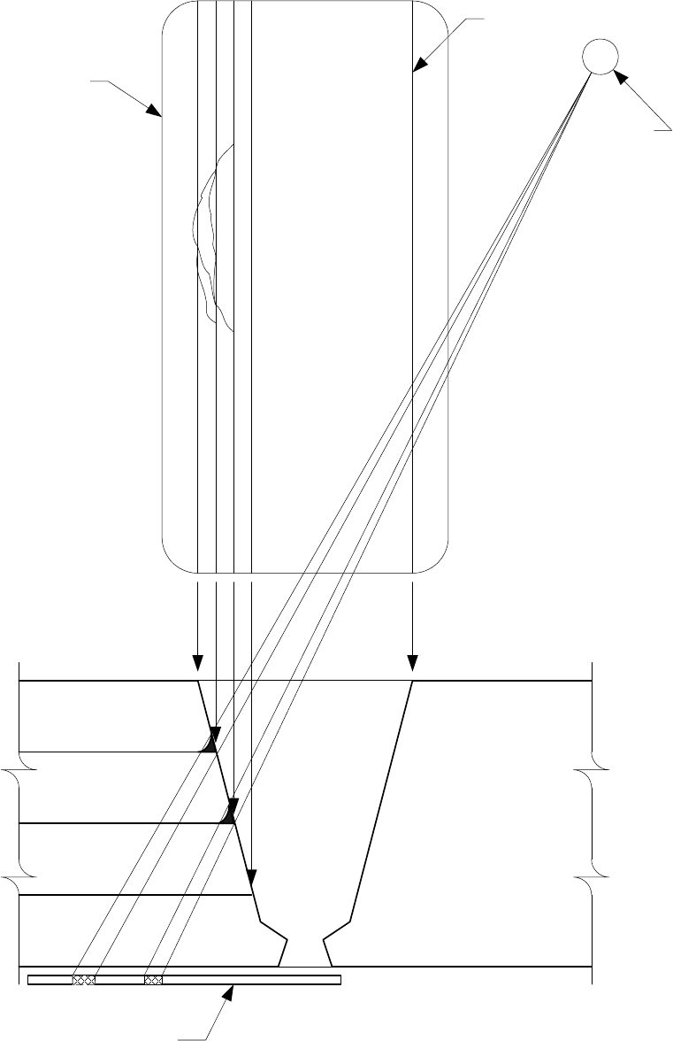
2010 SECTION VIII-2
7-35
Film or other
recording media
Fusion Line
Source
12
Approximate location
of radiation source for
angle shot
Film or other
recording media
Possible
Superimposed
Condition
(Indication)
Figure 7.2 – Examination of Layered Vessels
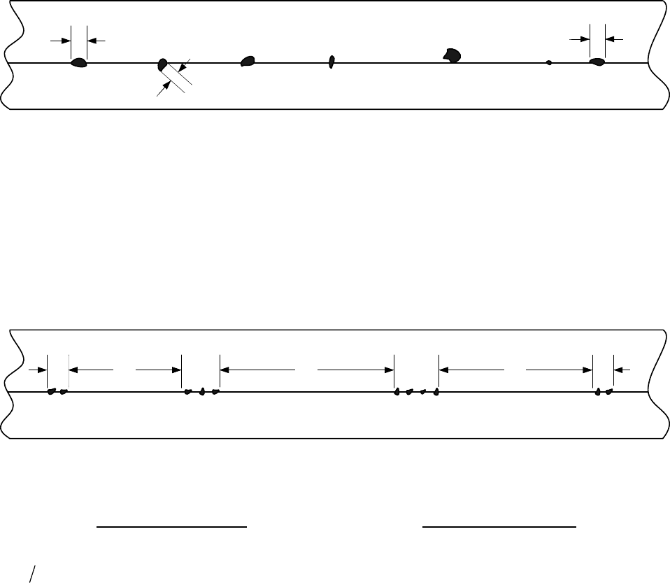
2010 SECTION VIII-2
7-36
L
2
L
x
L
1
Note: The sum of
1
L to
x
L shall be less than t in a length of
12t
.
Figure 7.3 – Aligned Rounded Indications
L
1
3L
2
L
2
3L
3
L
3
3L
3
L
4
Note: The sum of the group of lengths shall be less than
t in a length of 12t .
Maximum Group Length
Minimum Group Spacing
6(1/4)Lmm in=
for
19 (3 / 4 )tmm in<
3L where L is the length of the longest
adjacent group being evaluated
3Lt= for
19 (3 / 4 ) 57 (2 1/ 4 )mm in t mm in≤≤ −
19 (3/ 4 )Lmm in= for 57 (2 1/ 4 )tmm in>−
Figure 7.4 – Groups of Aligned Rounded Indications
标准分享网 www.bzfxw.com 免费下载
