ASME Section VIII div 2 2010. ASME Boiler and Pressure Vessel Code. Alternative Rules
Подождите немного. Документ загружается.

2010 SECTION VIII, DIVISION 2
5-139
ANNEX 5.F
EXPERIMENTAL STRESS AND FATIGUE ANALYSIS
(NORMATIVE)
5.F.1 Overview
5.F.1.1 The critical or governing stresses in parts may be substantiated by experimental stress analysis.
Experimental analysis may be used to determine governing stresses by strain measurement, and to evaluate
the adequacy of a part for cyclic loading.
5.F.1.2 The test procedures followed and the interpretation of the results shall be such as to discount the
effects of material added to the thickness of members, such as corrosion allowance or other material that
cannot be considered as contributing to the strength of the part.
5.F.1.3
Re-evaluation is not required for configurations for which there are available detailed experimental
results that are consistent with the requirements of this Annex.
5.F.1.4 The use of this Annex requires the approval of the user or an agent acting on behalf of the user and
the acceptance of its use shall be documented in the Manufacturer’s Design Report.
5.F.2 Strain Measurement Test Procedure for Stress Components
5.F.2.1 Permissible types of tests for the determination of governing stresses are strain measurement and
photoelastic tests. Either two-dimensional or three-dimensional photoelastic techniques may be used as long
as the model represents the structural effects of the loading.
5.F.2.2 Strain gages used may be of any type capable of indicating strains to 0.00005 in./in. (0.005%). It is
recommended that the gage length be such that the maximum strain within the gage length does not exceed
the average strain within the gage length by more than 10%. Instrumentation shall be such that both surface
principal stresses may be determined at each gage location in the elastic range of material behavior at that
gage location. A similar number and orientation of gages at each gage location are required to be used in
tests beyond the elastic range of material behavior. The strain gages and cements that are used shall be
shown to be reliable for use on the material surface finish, test temperature, and configuration considered to
strain values at least 50% higher than those expected.
5.F.2.3 Strain gage data may be obtained from the actual component or from a model component of any
scale that meets the gage length requirements defined in paragraph 5.F.2.2. The model material need not be
the same as the component material but shall have an elastic modulus that is either known or has been
measured at the test conditions. The requirements of dimensional similitude shall be met.
5.F.2.4 Sufficient locations on the vessel shall be investigated to ensure that measurements are taken at
the most critical areas. The location of the critical areas and the optimum orientation of test gages may be
determined by a brittle coating test.
5.F.2.5 Pressure gages shall meet the requirements of Part 8.
2010 SECTION VIII, DIVISION 2
5-140
5.F.2.6 The internal pressure or mechanical load shall be applied in such increments that the variation of
strain with load can be plotted so as to establish the ratio of stress to load in the elastic range. If the first
loading results in strains that are not linearly proportional to the load, then it is permissible to unload and
reload successively until the linear proportionality has been established. When frozen stress photoelastic
techniques are used, only one load value can be applied in which case the load shall not be so high as to
result in deformations that invalidate the test results. After all instrumentation has been deemed acceptable,
the test should be continued on a strain or displacement controlled basis with adequate time permitted
between load changes for all metal flow to be completed.
5.F.2.7 Linear elastic theory shall be used to determine the design load stresses from the strain gage data.
The calculations shall be performed under the assumption that the material is elastic. The elastic constants
used in the evaluation of experimental data shall be those applicable to the test material at the test
temperature.
5.F.2.8 The extent of experimental stress analysis performed shall be sufficient to determine the governing
stresses. When possible, combined analytical and experimental methods shall be used to distinguish
between primary, secondary, and peak stresses.
5.F.2.9 Stress determined by experimental results shall be evaluated for protection against plastic collapse
using the criterion in paragraph 5.2.2. Protection against cyclic loading shall be evaluated in accordance with
paragraphs 5.5.3 or 5.F.3.
5.F.2.10 Tests conducted in accordance with this paragraph do not need to be witnessed by the Inspector.
However, a detailed report of the test procedure and the results obtained shall be included with the Design
Report. The Report shall show that the instrumentation used was within calibration.
5.F.3 Protection Against Cyclic Loading
5.F.3.1 The adequacy of a vessel or part to withstand cyclic loading may be demonstrated by means of a
fatigue test in lieu of the methods of paragraph 5.5.3. The fatigue test shall not be used, however, as
justification for exceeding the allowable values of primary or primary plus secondary stresses. This procedure
shall not be used when the design temperature exceed the maximum temperature allowed for the fatigue
curves as given in Annex 3.F. This procedure shall not be used when the number of design cycles exceed
50,000.
5.F.3.2 When a fatigue test is used to demonstrate the adequacy of a component to withstand cyclic
loading, a description of the test shall be included in the Manufacturer’s Design Report. This description shall
contain sufficient detail to show compliance with the requirements of this Annex.
5.F.3.3 The test component or portion thereof shall be constructed of material having the same composition
and subjected to mechanical working and heat treatment that result in mechanical properties equivalent to
those of the material in the prototype component. Geometrical similarity must be maintained, at least in those
portions whose ability to withstand cyclic loading is being investigated and in those adjacent areas which
affect the stresses in the portion under test.
5.F.3.4 The test component or portion thereof shall withstand the number of cycles as set forth in paragraph
5.F.3.5 before failure occurs. Failure is herein defined as a propagation of a crack through the entire
thickness, such as would produce a measurable leak in a pressure retaining member.
5.F.3.5 The minimum number of cycles,
T
N , which the component must withstand, and the magnitude of
the loading,
T
L , to be applied to the component during test, shall be determined by multiplying the design
service cycles
D
N by a specified factor
TN
K and the design service loads
D
L by a specified factor
TS
K .
标准分享网 www.bzfxw.com 免费下载
2010 SECTION VIII, DIVISION 2
5-141
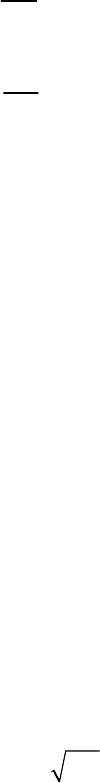
Values of these factors shall be determined by means of the test parameter ratio diagram, the construction of
which is as follows and is shown in Figure 5.F.1.
a) Project a vertical line from the design service cycles,
D
N , on the abscissa of the
a
S versus N diagram,
until the line intersects the fatigue design curve, label this point
aD
S . Determine the value of
s
aD
KS
⋅
to
establish point A. The parameter
s
K is determined using paragraph 5.F.3.9.
b) Extend a horizontal line through the point D from the ordinate axis to an abscissa value of
n
K times
D
N . Label this point B. This parameter
n
K is determined using paragraph 5.F.3.9.
c) Connect the points A and B. The segment AB embraces all the allowable combinations of
TS
K and
TN
K . Any point C on this segment may be chosen. The factors
TS
K and
TN
K are defined by the
following equations (see Figure 5.F.1).
aC
TS
aD
S
K
S
=
(5.F.1)
C
TN
D
N
K
N
=
(5.F.2)
Therefore,
TTSD
LKL=⋅ (5.F.3)
TTND
NKN=⋅ (5.F.4)
5.F.3.6 It should be noted that if the test article is not a full size component but a geometrically similar
model, the value
T
L would have to be adjusted by the appropriate scale factor, to be determined from
structural similitude principles, if the loading is other than pressure. The number of cycles that the component
must withstand during this test without failure must not be less than
T
N , while subjected to a cyclic test
loading
T
L which shall be adjusted, if required, using model similitude principles if the component is not full
size.
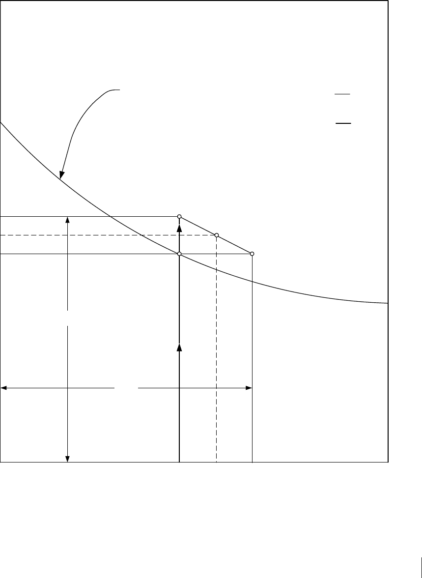
5.F.3.7 Accelerated fatigue testing (test cycles
T
N are less than design cycles
D
N ) may be conducted if
the design cycles
D
N are greater than 10
4
and the testing conditions are determined by the following
procedures which are illustrated in Figure 5.F.2. In this figure, the points A, B, and D correspond to similar
labeled points in Figure 5.F.1.
a) The minimum number of test cycles
minT
N is given by Equation (5.F.5). Project a vertical line through
minT
N on the abscissa of the
a
S versus N diagram such that it intersects and extends beyond the
fatigue design curve.
2
min
10
TD
NN= (5.F.5)

2010 SECTION VIII, DIVISION 2
5-142
b) Project a vertical line from the design service cycles,
D
N , on the abscissa of the
a
S versus N diagram,
until the line intersects the fatigue design curve, label this point
aD
S . Determine the value of
s
aD
KS
⋅
to
establish point A. The parameter
s
K is determined using paragraph 5.F.3.9.
c) Construct a curve through the point A by multiplying all of the ordinate values (Sa values) on the fatigue
design curve by the factor
S
K . Label the intersection of this curve and a vertical line projection of
minT
N
as A'.
d) Any point C on the segment A’, A, B determines the allowable combinations of
TS
K and
TN
K . The
factors
TS
K and
TN
K are obtained in the same manner as in paragraph 5.F.3.5.
5.F.3.8 In certain instances, it may be desirable (or possible) in performing the test to increase only the
loading or number of cycles, but not both, in which event two special cases of interest result from the above
general case.
a) Case 1 (Factor Applied to Cycles Only) – In this case
1
TS
K
=
and the value of
TN
K is determined by
Equation (5.F.6). The number of test cycles that the component shall withstand during this test shall not
be less than given by Equation (5.F.7) while subjected to the cyclic design
service loading, adjusted as
required, if a geometrically similar model is used.
B
TN
D
N
K
N
=
(5.F.6)
TBTND
NNKN== ⋅ (5.F.7)
b) Case 2 (Factor Applied to Loading Only) – In this case
1
TN
K
=
and the value of
TS
K is determined by
Equation (5.F.8). The component shall withstand a number of cycles at least equal to the number of
design service cycles given by Equation
(5.F.9) while subjected to a cyclic test loading again adjusted as
required, if a geometrically similar model is used.
aA
TS
aD
S
K
S
=
(5.F.8)
TTSD
LKL=⋅ (5.F.9)
5.F.3.9 The values of
n
K and
s
K are the multiples of factors which account for the effects of size, surface
finish, cyclic rate, temperature, and the number of replicate tests performed. They shall be determined as
follows:
4.3
max ( ) , 2.6
ns
KK
⎡⎤
=
⎣⎦
(5.F.10)
()
max , 1.25
s scslsf stss
K KKKKK
⎡⎤
=⋅⋅⋅⋅
⎣⎦
(5.F.11)
where:
()
()
()
()
,
max , 1.0
,
aCaeT
sc
aDaeC
SNT S T
K
SNT S T
⎡⎤
⎛⎞
=⋅
⎢⎥
⎜⎟
⎜⎟
⎢⎥
⎝⎠
⎣⎦
(5.F.12)
标准分享网 www.bzfxw.com 免费下载

2010 SECTION VIII, DIVISION 2
5-143
()
max 1.5 0.5 , 1.0
sl LP
KR=−
⎡⎤
⎣⎦
(5.F.13)
()
max 1.175 0.175 , 1.0
sf SF
KR=−
⎡⎤
⎣⎦
(5.F.14)
()
()
,
max , 1.0
,
aT
st
aD
SNT
K
SNT
⎡⎤
⎛⎞
=
⎢⎥
⎜⎟
⎜⎟
⎢⎥
⎝⎠
⎣⎦
(5.F.15)
()
max 1.470 0.044 , 1.0
ss RT
KN=−⎡⎤
⎣⎦
(5.F.16)
5.F.3.10 Experimental determination of fatigue strength reduction factors shall be in accordance with the
following procedures.
a) The test part shall be fabricated from a material within the same P-Number grouping, and shall be
subjected to the same heat treatment as the component.
b) The stress level in the specimen shall be such that the equivalent stress satisfies Equation (5.F.17) .
()
L
bPS
PPQ S++ ≤ (5.F.17)
c) The configuration, surface finish, and stress state of the specimen shall closely simulate those expected
in the components. In particular, the stress gradient shall not be less abrupt than that expected in the
component.
d) The cyclic rate shall be such that appreciable heating of the specimen does not occur.
e) The fatigue strength reduction factor shall preferably be determined by performing tests on notched and
unnotched specimens, and calculated as the ratio of the unnotched stress to the notched stress for
failure.
5.F.4 Nomenclature
n
K multiplier to design cycles that accounts for the effects of size, surface finish, cyclic rate,
temperature, and the number of replicate tests performed.
s
K multiplier to design allowable stress that accounts for the effects of size, surface finish,
cyclic rate, temperature, and the number of replicate tests performed.
s
c
K factor for differences in design fatigue curves at various temperatures.
s
f
K factor for the effect of surface finish.
s
kin
K stress multiplier for thermal skin stress.
s
l
K factor for the effect of size on fatigue life.
TN
K multiplier for test cycles.
TS
K multiplier for test loading.
s
s
K factor for the statistical variation in test results.
s
t
K factor for the effect of test temperature.
D
L design service loading.
T
L cyclic test loading.
2010 SECTION VIII, DIVISION 2
5-144
B
N fatigue cycles at point B.
C
N fatigue cycles at point C.
D
N design cycles.
RT
N number of replicate tests.
T
N test cycles.
minT
N minimum number of test cycles.
b
P primary bending stress intensity.
L
P local primary membrane stress intensity.
Q secondary stress intensity.
LP
R
ratio of model linear size to the linear size of the fabricated part
SF
R
ratio of model surface finish to surface finish of the fabricated part
a
S alternating stress obtained from a fatigue curve for the specified number of operating
cycles.
aA
S alternating stress at point A.
aC
S alternating stress at point C.
aD
S alternating stress at point D .
()
,
aC
SNT stress amplitude from the applicable design fatigue curve (see Annex 3.F) for N cycles
evaluated at
C
T .
()
,
aD
SNT stress amplitude from the applicable design fatigue curve (see Annex 3.F) for
N
cycles
evaluated at the design temperature,
D
T .
()
,
aT
SNT stress amplitude from the applicable design fatigue curve (see Annex 3.F) for N cycles
evaluated at the test temperature,
T
T .
()
ae C
ST stress amplitude from the applicable design fatigue curve (see Annex 3.F) at the
maximum number of cycles defined on the curve (possibly the endurance limit) evaluated
at
C
T .
()
ae T
ST stress amplitude from the applicable design fatigue curve (see Annex 3.F) at the
maximum number of cycles defined on the curve (possibly the endurance limit) evaluated
at the test temperature,
T
T .
as
S stress from the applicable design fatigue curve (see Annex 3.F). If the design cycles is
greater than
6
10
, then
as
S is determined from the fatigue curve at
6
10
cycles; otherwise,
as
S is taken as the stress associated with the maximum number of cycles on the design
fatigue curve.
C
T component temperature.
D
T design temperature.
T
T test temperature.
标准分享网 www.bzfxw.com 免费下载
2010 SECTION VIII, DIVISION 2
5-145
5.F.5 Figures
B
C
A
D
N
D
N
B
N
C
S
aD
S
aC
S
aA
Number of Cycles N
Value of S
a
, psi (kPa)
Design Fatigue Curve
For point C
K
TS
=
K
TN
=
S
aC
S
aD
N
C
N
D
K
n
N
D
K
s
S
aD
Figure 5.F.1
Construction Of The Testing Parameter Ratio Diagram
2010 SECTION VIII, DIVISION 2
5-146
B
C
A'
D
N
Tmin
N
D
N
C
S
aD
S
aC
Number of Cycles N
Value of S
a
, psi (kPa)
Design Fatigue Curve
For point C
K
TS
=
K
TN
=
S
aC
S
aD
N
C
N
D
A
Design Fatigue Curve
Multiplied by K
S
Figure 5.F.2
Construction Of The Testing Parameter Ratio Diagram For Accelerated Tests
标准分享网 www.bzfxw.com 免费下载
2010 SECTION VIII, DIVISION 2
6-1
PART 6
FABRICATION REQUIREMENTS
PART CONTENTS
6.1 General Fabrication Requirements ...................................................................................... 6-3
6.1.1 Materials ........................................................................................................................ 6-3
6.1.2 Forming ......................................................................................................................... 6-4
6.1.3 Base Metal Preparation ................................................................................................. 6-6
6.1.4 Fitting and Alignment ..................................................................................................... 6-7
6.1.5 Cleaning of Surfaces to Be Welded .............................................................................. 6-8
6.1.6 Alignment Tolerances for Edges to Be Butt Welded ...................................................... 6-8
6.2 Welding Fabrication Requirements ...................................................................................... 6-9
6.2.1 Welding Processes ........................................................................................................ 6-9
6.2.2 Welding Qualifications and Records ............................................................................. 6-9
6.2.3 Precautions to Be Taken Before Welding ..................................................................... 6-11
6.2.4 Specific Requirements for Welded Joints ..................................................................... 6-11
6.2.5 Miscellaneous Welding Requirements ........................................................................ 6-13
6.2.6 Summary of Joints Permitted and Their Examination ................................................. 6-14
6.2.7 Repair of Weld Defects ................................................................................................ 6-14
6.2.8 Special Requirements for Welding Test Plates for Titanium Materials ........................ 6-15
6.3 Special Requirements for Tube-To-Tubesheet Welds ....................................................... 6-15
6.3.1 Material Requirements ................................................................................................ 6-15
6.3.2 Holes in Tubesheets .................................................................................................... 6-15
6.3.3 Weld Design and Joint Preparation ............................................................................. 6-15
6.3.4 Qualification of Welding Procedure ............................................................................. 6-15
6.4 Preheating and Heat Treatment of Weldments .................................................................. 6-15
6.4.1 Requirements for Preheating of Welds ....................................................................... 6-15
6.4.2 Requirements for Postweld Heat Treatment ............................................................... 6-16
6.4.3 Procedures for Postweld Heat Treatment ................................................................... 6-17
6.4.4 Operation of Postweld Heat Treatment ....................................................................... 6-19
6.4.5 Postweld Heat Treatment after Repairs ...................................................................... 6-19
6.4.6 Postweld Heat Treatment of Nonferrous Materials ..................................................... 6-20
6.5 Special Requirements For Clad or Weld Overlay Linings, and Lined Parts ....................... 6-21
6.5.1 Materials ...................................................................................................................... 6-21
6.5.2 Joints In Corrosion Resistant Clad or Weld Metal Overlay Linings ............................. 6-22
6.5.3 Welding Procedures .................................................................................................... 6-22
6.5.4 Methods to Be Used In Attaching Applied Linings ....................................................... 6-22
6.5.5 Postweld Heat Treatment of Clad and Lined Weldments ............................................ 6-22
6.5.6 Requirements for Base Material With Corrosion Resistant Integral or
Weld Metal Overlay Cladding ............................................................................................ 6-22
6.5.7 Examination Requirements ......................................................................................... 6-23
6.5.8 Inspection and Tests .................................................................................................... 6-23
6.5.9 Stamping and Reports ................................................................................................. 6-23
6.6
Special Requirements for Tensile Property Enhanced Q and T Ferritic Steels ................. 6-23
6.6.1 General ........................................................................................................................ 6-23
2010 SECTION VIII, DIVISION 2
6-2
6.6.2 Marking on Plates and Other Materials ....................................................................... 6-23
6.6.3 Requirements for Heat Treating After Forming ............................................................ 6-23
6.6.4 Minimum Thickness after Forming ............................................................................... 6-23
6.6.5 Welding Requirements ................................................................................................. 6-24
6.6.6 Postweld Heat Treatment ............................................................................................. 6-26
6.6.7 Heat Treatment Certification Tests ............................................................................... 6-27
6.6.8 Examination Requirements .......................................................................................... 6-28
6.6.9 Inspection and Tests .................................................................................................... 6-28
6.6.10 Stamping and Reports .................................................................................................. 6-28
6.7 Special Requirements for Forged Fabrication .................................................................... 6-28
6.7.1 General ........................................................................................................................ 6-28
6.7.2 Ultrasonic Examination ................................................................................................ 6-28
6.7.3 Toughness Requirements ............................................................................................ 6-28
6.7.4 Tolerances on Cylindrical Forgings .............................................................................. 6-28
6.7.5 Methods of Forming Forged Heads ............................................................................. 6-29
6.7.6 Heat Treatment Requirements for Forged Fabrication ................................................ 6-29
6.7.7 Welding For Fabrication ............................................................................................... 6-30
6.7.8 Repair of Defects in Material ........................................................................................ 6-31
6.7.9 Threaded Connections to Vessel Walls, Forged Necks, and Heads ........................... 6-32
6.7.10 Inspection, Examination, and Testing .......................................................................... 6-32
6.7.11 Stamping and Reports for Forged Vessels .................................................................. 6-33
6.7.12 Pressure Relief Devices ............................................................................................... 6-33
6.8 Special Fabrication Requirements for Layered Vessels ..................................................... 6-33
6.8.1 General ........................................................................................................................ 6-33
6.8.2 General Fabrication Requirements .............................................................................. 6-33
6.8.3 Welding Fabrication Requirements .............................................................................. 6-33
6.8.4 Welding Qualification and Records .............................................................................. 6-33
6.8.5 Specific Requirements for Welded Joints .................................................................... 6-34
6.8.6 Nondestructive Examination of Welded Joints............................................................. 6-35
6.8.7 Welded Joint Efficiency ................................................................................................ 6-35
6.8.8 Contact between Layers .............................................................................................. 6-35
6.8.9 Vent Holes .................................................................................................................... 6-35
6.8.10 Heat Treatment of Weldments ..................................................................................... 6-36
6.9 Nomenclature ...................................................................................................................... 6-37
6.10 Tables ................................................................................................................................. 6-38
6.11 Figures ................................................................................................................................ 6-62
标准分享网 www.bzfxw.com 免费下载