ASM Metals HandBook Vol. 8 - Mechanical Testing and Evaluation
Подождите немного. Документ загружается.

extension under load, and so on. Yield strength may be determined by the offset method or the extension-under-
load method.
To determine the yield strength by the offset method, it is necessary to secure data (autographic or numerical)
from which a stress-strain diagram may be drawn. Then, on the stress-strain diagram layoff, o-m, as shown in
Fig. 11, equal to the specified value of the offset, m-n should be drawn parallel to o-A and thus locate r. The
yield-strength load, R, is the load corresponding to the highest point of the stress-strain curve before or at the
intersection of m-n and r. In reporting values of yield strength obtained by this method, the specified value of
the offset used should be stated in parenthesis after the term yield strength, thus:
Yield strength (0.2% offset) = 360 MPa
In using this method, a minimum extensometer magnification of 250 to 1× is required. A class B1 extensometer
meets this requirement.
The extension-under-load method is used to determine the acceptance or rejection of materials whose stress-
strain characteristics are well known from previous tests of similar materials in which stress-strain diagrams are
plotted. For these tests, the total strain corresponding to the stress at which the specified offset occurs should be
known as within satisfactory limits. The stress on the specimen, when total strength is reached, is the value of
the yield strength. The total strain can be obtained satisfactorily by the use of a class B1 extensometer. The
extension under load (mm/mm of gage length) can be determined as follows:
YS/E = R
(Eq 2)
where YS is the specified yield strength, MPa; E is the modulus of elasticity, MPa; and r is the limiting plastic
strain, mm/mm.
Tensile strength is calculated by dividing the maximum load the specimen sustains during a tension test by the
original cross-sectional area of the specimen.
Elongation. The ends of the fractured specimen are fitted together carefully and the distance between the gage
marks measured to the nearest 0.25 mm for gage lengths of 50 mm or under, and to the nearest 0.5 mm of the
gage length for gage lengths over 50 mm. A percentage scale reading to 0.5% of the gage length may be used.
The elongation is the increase in length of the gage length, expressed as a percentage of the original gage
length. In reporting elongation values, both the percentage increase and the original gage length should be
given.
If any part of the fracture takes place outside the middle half of the gage length or in a punched or scribed mark
with the reduced section, the elongation value obtained may not be representative of the material. If the
elongation so measured meets the minimum requirements specified, no further testing is indicated, but if the
elongation is less than the minimum requirements, the test should be discarded and performed again.
Reduction of Area. The ends of the fractured specimen are fitted together and the mean diameter or the width
and thickness at the smallest cross section measured to the same accuracy as the original dimensions. The
difference between the area thus found and the area of the original cross section expressed as a percentage of
the original area is the reduction in area.
Total Extension at Fracture Test. The test to determine extension at fracture, A
L
, is carried out on stainless steel
and nonferrous products in the finished condition with the length equal to or in excess of those minimums listed
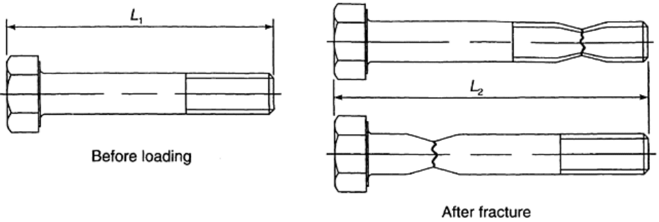
in Table 1. The products to be tested are measured for total length, L
1
, described as follows and shown in Fig.
14.
Fig. 14 Determination of total extension at fracture (A
L
) for a screw product. Source: Ref 1
Both ends of the fastener or stud are marked using a permanent marking substance, such as bluing, so that the
measuring reference points for determining total lengths, L
1
and L
2
, are established. An open-end caliper and
steel rule or other device capable of measuring to within 0.25 mm are used to determine the total length of the
product (Fig. 14).
The product under test is screwed into the threaded adapter to a depth of one diameter (Fig. 6) and load applied
axially until the product fractures. The maximum speed of the freerunning cross head should not exceed 25
mm/min.
After the product has been fractured, the two broken pieces are fitted closely together, and the overall length,
L
2
, is measured. The total extension at fracture, A
L
, is then calculated as follows:
A
L
= L
2
- L
1
(Eq 3)
The value obtained should equal or exceed the minimum values shown in the applicable specification for the
product and material type.
Test Methods for Internally Threaded Fasteners
Product Hardness. For routine inspection, hardness of nuts may be determined on the bearing face or wrench
flats after removal of any plating or coating. Rockwell or Vickers hardness testing may be used at the option of
the manufacturer, taking into account the size and property class of the nut. The reported hardness is a
minimum of two hardness readings taken 180° apart, halfway between the major diameter of the thread and one
corner or, if applicable, on a wrench face one-third of the distance from a corner to the center of the wrench
face. In preparation of the surface, sufficient material is removed to ensure elimination of any oxide,
decarburization, coating, or other surface irregularities. The preparation of test specimens and the performance
of hardness tests for Rockwell or Vickers testing are in conformity with the requirements of ASTM E 18 and E
92, respectively. For the purpose of arbitration, hardness is taken on a longitudinal section through the nut axis
with readings taken as closely as possible to the nominal major diameter of the nut thread.
Proof-Load Test. The nut to be tested is assembled on a hardened threaded mandrel or a test bolt using the
tension method (Fig. 15a) or the compression method (Fig. 15b). The hardened test mandrel and the tension
method shown in Fig. 15(a) is mandatory as a reference if arbitration is necessary. The specified proof load is
applied for the nut against the nut. The nut should resist this load without stripping or rupture and should be
removable from the test bolt or mandrel by the fingers after the load is released. Occasionally, it may be
necessary to use a manual wrench or other means to start the nut in motion. Use of such means is permissible,
provided the nut is removable by the fingers following the initial loosening of not more than one-half turn of
the nut. If the threads of the mandrel or test bolt are damaged during the test, the test should be discarded.
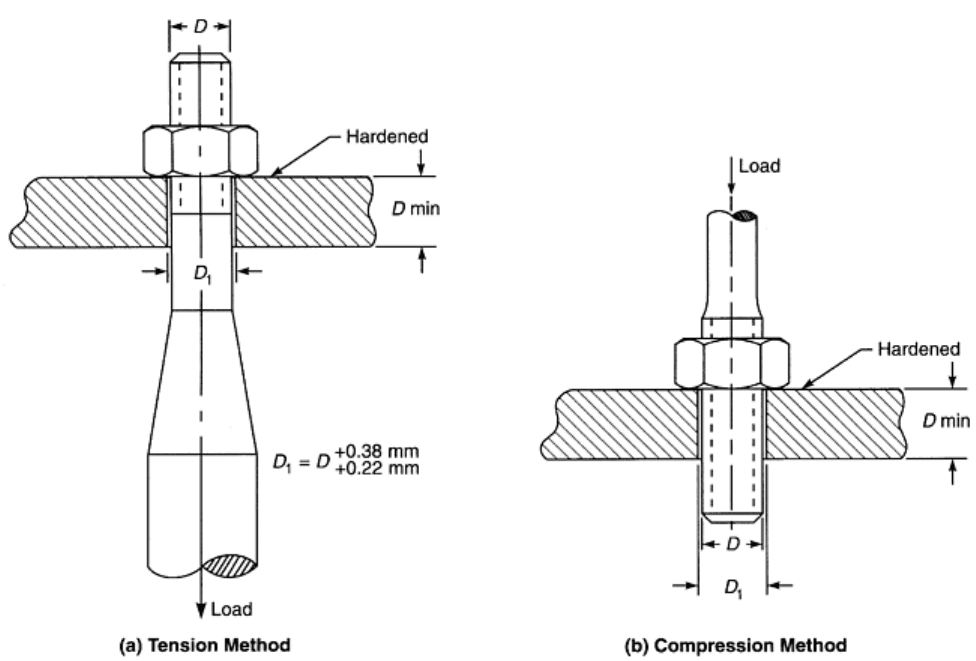
Fig. 15 Proof-load testing of nuts. Source: Ref 1
The test fastener should be appropriate to the standard specified for the nut being tested and should have a yield
strength in excess of the specified proof load of the nut being tested. Mandrels should have a hardness of 45
HRC minimum; the mandrel should have threads conforming to the same standards as those specified for the
nut being tested, except that the maximum major diameter is the specified minimum major diameter for class
4H6H threads and the maximum major diameter plus 0.25 times the major diameter tolerance of class 4H6H
threads.
The proof load is determined at a free-running cross head not exceeding 25 mm/min and is held at load for a
minumum of 10 s.
Cone proof-load tests should be performed by the use of a conical washer and threaded mandrel (Fig. 16) to
determine the influence of surface discontinuities (forging cracks and seams) on the load-carrying ability of
hardened steel nuts through 36 mm in diameter by introducing a simultaneous dilation and stripping action of
the nut. The conical washer should have a hardness of 57 HRC minimum and a hole diameter of the mandrel
+0.05 mm and -0.00 mm. The contact point of the cone should be sharp for nut sizes 12 mm or less. For sizes
greater than 12 mm, the point should be flat and 0.38 ± 0.03 mm in width. The nut and the conical washer are
assembled on the mandrel and the cone proof load applied for the nut against the nut. The speed of testing as
determined with a free-running cross head should be a maximum of 3 mm/min. Apply the proof load for 10 s.
The proof load of the nut is computed as follows:
CPL = (1 - 0.012D) f × A
s
× 0.001
(Eq 4)
where CPL is the cone proof load, kN; D is the nominal diameter of the nut, mm; f is the specified proof stress
of the nut, MPa; A
s
is the tensile stress area of the nut, mm
2
, equal to 0.7854 [D - (0.9382P)]
2
; and P is the
thread pitch, mm.
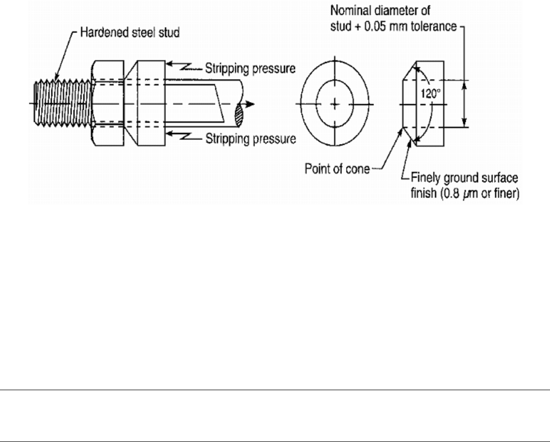
Fig. 16 Cone-proof test. Source: Ref 1
To meet the requirements of the cone proof-load test, the nut should support its specified cone proof load
without stripping or rupture.
Reference cited in this section
1. “Standard Test Methods for Determining the Mechanical Properties of Externally and Internally
Threaded Fasteners, Washers, and Rivets (Metric),” F 606M, Annual Book of ASTM Standards, ASTM
Mechanical Testing of Threaded Fasteners and Bolted Joints
Ralph S. Shoberg, RS Technologies, Ltd.
Friction Coefficient Testing
This section describes the testing method for a tightening test to determine the coefficients of friction of
assemblies using threaded fasteners under specified conditions. A standardized measurement and analysis
procedure is presented for comparison of assemblies with different surface finishes or for cases where different
coatings, plating processes, or lubricants are used.
The results of testing in accordance with this test specification can provide valuable insights as to the expected
behavior of actual bolted-joint assemblies. Additional testing and analysis, including computer modeling, is
necessary to confirm the influence of frictional components of torque in actual assemblies. Torque-angle
signatures plotted from tests on actual assemblies can be best understood if accurate friction coefficient data are
available for modeling the bolted-joint-tightening process.
The frictional coefficient data obtained are necessary for the design and testing of bolted assemblies. In the final
analysis, it is impossible to accurately model or calculate a bolted-joint design if correct friction coefficient
information is not known.
Principle
A tightening torque is steadily applied to a bolted-joint assembly at ambient temperature. In the range of elastic
deformation, there is a linear relationship between torque and clamping load. This relationship is expressed by
the following equation applicable to bolted-joint assemblies with ISO metric threads and to other screw threads

with triangular profiles and a 60° pitch angle as specified in ISO 68:1973 or ASME B1.13M-1995 (“Metric
Screw Threads—M Profile”):
(Eq 5)
where terms on the right side are defined in Eq 6, 7, 8, 9, 10, 11, and 12. The applied torque, T
A
, is composed of
a component acting in the thread and serving to both apply the proofing load and to overcome thread-friction
torque, T
G
. It also comprises a component acting at the bolt head or nut-bearing face, termed underhead friction
torque, T
K
.
T
A
= T
G
+ T
K
(Eq 6)
where
T
G
= F
V
(0.159 · P + 0.578 · d
2
· μ
G
)
(Eq 7)
where d
2
is the bolt thread pitch diameter, and where
(Eq 8)
The mean diameter required for measuring the coefficient of friction acting at the bearing face of the bolt head
or nut is calculated from the following equation:
(Eq 9)
where d
w
is the external diameter of the bearing face for frictional torque, and d
h
is the clearance hole diameter.
Equation 9 applies to plane-bearing surfaces located vertically to the bolt axis. In other cases, such as in the
case of screws with a conical bearing face, D
Km
is the nominal mean diameter of the conical contact area.
Suitable allowance should be made for bearing faces that differ in form, such as countersunk heads or spherical
faces.
Determination of the coefficients of friction are based on the relationships obtained when transforming Eq 7
and 8, such as the following thread friction coefficient:
(Eq 10)
and the following underhead friction coefficient:
(Eq 11)
where the test apparatus does not permit a separate measurement of T
G
and T
K
, a reference coefficient of
friction may be calculated from the following equation (reference friction coefficient):
(Eq 12)
This equation is derived from Eq 10 and 11 assuming μ
G
= μ
K
. The above coefficient can be used only for
assessment of the overall friction behavior of bolted joint assemblies and is not suitable for the design of bolted
connections in general. Because the test results are influenced by a variety of parameters, minimum
requirements for the test procedure have been specified in the sections “Test Equipment” and “Procedure.”
The statement of this principle can be extended to cover determination of K, which is often referred to as the
nut factor and is a function of thread and underhead friction coefficients as well as thread pitch and diameter.
Basic threaded-fastener theory states that the torque required to tighten the joint is the product of the friction in
the joint, K, the diameter of the fastener, D, and the applied force, F
V
. This theory is represented by the
following formula:
T = K · D · F
V
(Eq 13)
Because the applied torque is the result of the torque required to overcome friction in the threads, T
G
, and the
torque required to overcome friction in the underhead area, T
K
, the basic equation can be restated as
T
A
= K · d · F
V
= T
G
+ T
K
(Eq 14)
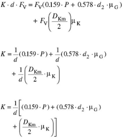
By substituting the expressions for T
G
and T
K
from Eq 3 and 4, we obtain the following equation:
(Eq 15)
Placing the equation in terms of K, we obtain the following:
(Eq 16)
Simplifying terms results in the following equation:
(Eq 17)
The three elements in the above equation represent the components of K as related to pitch, thread, and
underhead friction torque. When tightening nut and bolt assemblies, it should be understood that, depending on
the frictional torque factors, the value of K could be different during tightening when either the nut or bolt is
turned. For a given tension, the thread torque will always be the same, while the underhead torque depends on
which element (nut or bolt) is turned. The value for K can be best understood and accurately represented only if
the thread and underhead friction coefficients are determined. Simple torque-tension tests without friction
coefficient determination capability do not provide enough information to precisely locate the source of
variability in k-factors.
Test Equipment
The test equipment should be capable of fixturing the test bolt, nut, and washer. This equipment must also be
capable of recording the torque- and force-related data. Care should be taken to ensure that whichever part (bolt
or nut) is not moved during tightening of the assembly and the washer are both held firmly in place. Figure 17
shows an illustration of a typical test setup using a thread torque and fastener tension load cell.
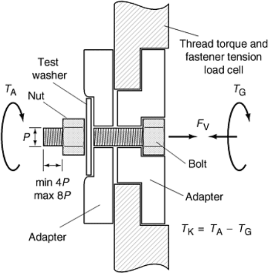
Fig. 17 Cutaway of typical test setup using torque-tension research head. T
A
, tightening torque for
generating load F
V
; T
G
, component of tightening torque acting in threads; T
K
, frictional torque acting at
bearing face of bolt head or nut; P, thread pitch
In cases of arbitration, only such coefficients of friction may be compared that have been determined using the
same apparatus, the same washer, and a bolt and nut with the same thread. The measuring system should permit
determination of T
A
, T
G
, T
K
, and F
V
with a limit of error of ±3% at the point of measurement (a discussion can
be found in the section “Measurement Accuracy” in this article).
Procedure
Each test should be carried out with a set of new bolts, nuts, and washers with the property classes of bolt and
nut being compatible.
When investigating the effect of lubricants on the tightening process, a special test setup may be specified,
which then may be used for a series of tightening tests. In such cases, the bolt, nut, and washer all have the
status of reference components.
Mounting of Bolt and Nut. The bolt and nut assembly to be tested should be clamped into the apparatus so that
the bolt end projects beyond the surface of the nut when fitted for a maximum number of eight turns of thread.
On the shank side of the nut, there should be at least two complete turns of thread not engaged.
The test washer should be constructed with material properties and finish representative of the bearing surface
for which friction coefficient data are to be obtained. Where no particular agreements have been made as to the
condition of the washer or type under that part of the assembly, which is rotated in the tightening process, steel
washers can be used. The washers are required to have the following characteristics (DIN 946 contains further
details):
• Polished lengthwise with surface roughness average, R
a
, of 0.8 to 1.6 μm
• Flatness tolerance and parallelism tolerance, each of 0.04 mm
• Bright and degreased
• Minimum thickness of 0.5 d
• Hardness 38 to 42 HRC or 380 to 420 HV20
• Clearance hole diameter, d
h
= d
a
(max), maximum internal bearing diameter (tolerance H 13), not
countersunk
This list is intended as a sample specification that can be used as a model for definition of test washers in
general. For simulation of production, component sections of actual parts can be made into washer coupons.
Fixtures can often be fabricated to permit mounting unmodified components on the research head for efficient
testing of as-manufactured surfaces.
Thread Tolerance for and Surface Finish of Reference Components. The surface finish and thread tolerance for
reference components should comply with the following specifications appropriate to the parts to be evaluated.
For example, DIN 946 suggests the following specifications for bolts and nuts used to evaluate lubricants and
coatings:
• Where bolts are to be tested, nuts with a bright finish should be used as reference components,
degreased and capable of being fully loaded with thread manufactured to a tolerance of 6 H. If the bolt
cannot be easily screwed in by hand, nuts with thread manufactured to a larger tolerance should be used.
• Where nuts are to be tested, zinc-phosphated bolts should be used as reference components, degreased
and with thread manufactured to a tolerance of 6 g. The coated bolt should permit the nut to be easily
mounted by hand.
• When investigating the effects of lubricants, bolts and nuts that comply with the requirements specified
under the preceding two items should be used.
In general, it is necessary that finishes and tolerances of test components be adequately defined to permit
replication of test conditions.
Tightening Rate Specification (rpm). In order to standardize testing conditions, it is necessary to closely control
tightening speed (rpm). Maintenance of a constant turning rate is essential to obtaining comparable results. The
recommended tightening rate of the assembly is 30 rpm as specified by DIN 946. Certain locknut testing
standards require 100 rpm. In general, larger fasteners must be run at slower speeds to achieve uniform,
predictable results. Depending on the surface coatings, lubricants, and size of fasteners, testing speeds as low as
5 to 10 rpm may be necessary to ensure repeatable results. Because production tools are often selected
improperly, based upon high speed capability, extreme caution must be taken to verify tension obtained on
actual assemblies.
Evaluation
The coefficients of friction are determined from Eq 9, 10, 11, and 12, making allowance for the geometry of
bolt, nut, and washer for the torque applied and the proofing load generated.
Using Eq 9, 10, 11, and 12, the following parameters are entered: nominal sizes of d
2
, P, and d
h
, and the size of
d
w
in accordance with the relevant product standard.
Evaluation of the test results may best be made by reading the coefficients of friction from the diagrams plotted
on the basis of Eq 7 and 8. Normally, the minimum value of d
w
as specified in the relevant product standard is
to be entered in these equations. The maximum hole size or chamfer diameter is used for d
h
.
The test results should be plotted, where possible, in a single graph for ease of comparison. Where bolt and nut
assemblies are to be subjected to repeated tightening and loosening cycles, the results for each assembly may be
plotted separately to minimize confusion. Evaluation should be based on a proofing load obtained for an
average value of μ
G
, μ
K
, or μ
ges
as determined by testing as specified in VDI 2230, Part 1.
By way of simplification, for normal values of μ, from 0.10 to 0.16, evaluation may be based on a value of F
V
equal to 0.7 · F
0.2
(nominally, 70% of yield load).
Outliers are ignored only if they can be definitely assigned to abnormal influences, such as a chip caught in a
thread and so on. As a rule, the evaluation should be based on 12 tests. A different number of tests may be
agreed upon between the concerned parties.
Test Report
It is recommended that test results reported include maximum, mean, and minimum values and the standard
deviation based upon n-1 sample calculation, assuming a normal distribution. In the test report, the coefficients
of friction, normally minimum and maximum values, should be given together with details of the test
conditions as itemized in the section “Procedure,” stating any deviations from these conditions. The test report
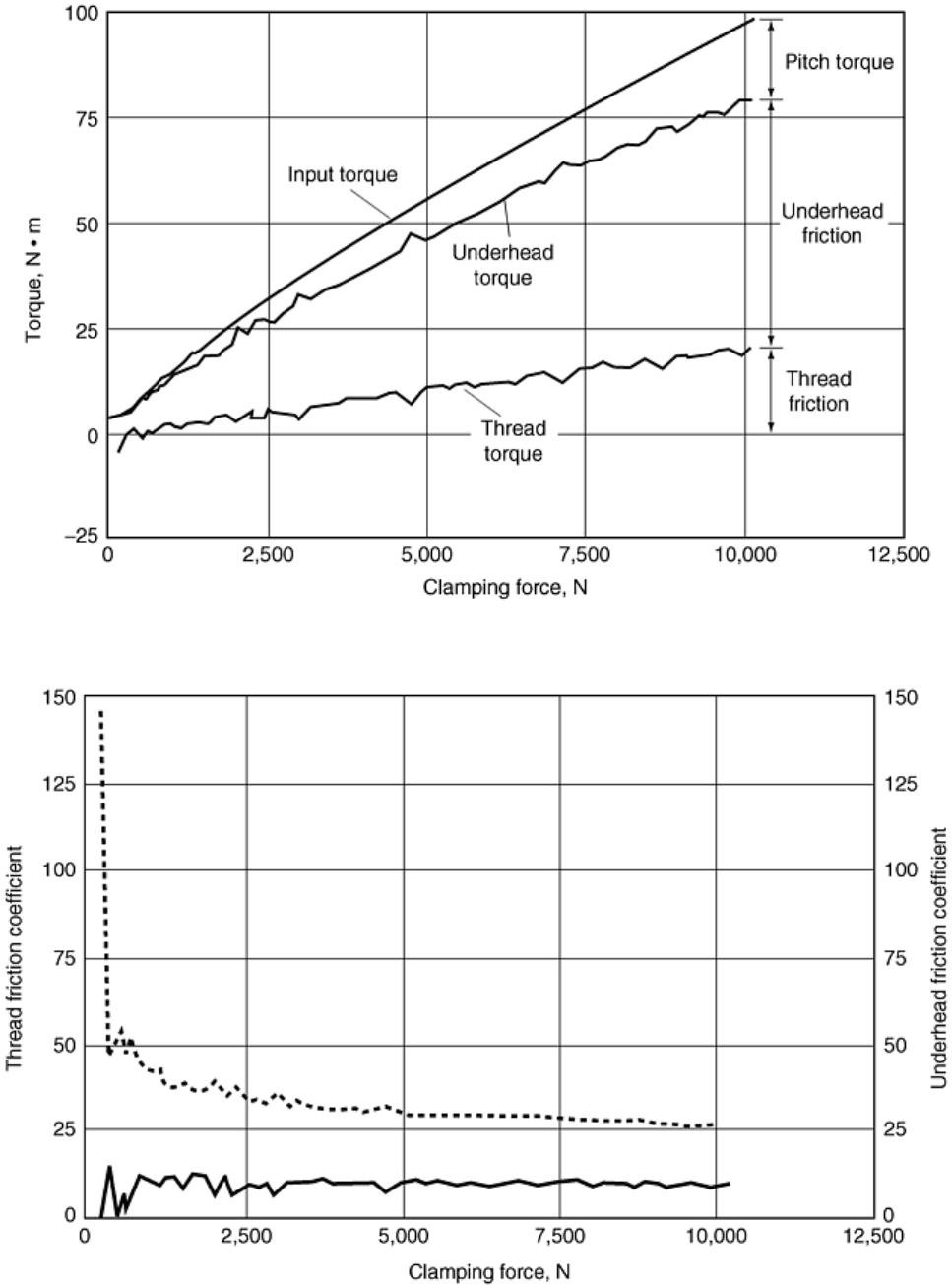
also should include any graphic data that the test equipment is capable of providing. For example, Fig. 18
shows the breakdown of the torque measurements. Figure 19 shows the calculated friction coefficients relating
to thread and underhead torque. Figure 20 shows the k-factor as a function of the achieved force.
Fig. 18 Torque measurements for friction determination
Fig. 19 Calculated thread and underhead friction coefficients
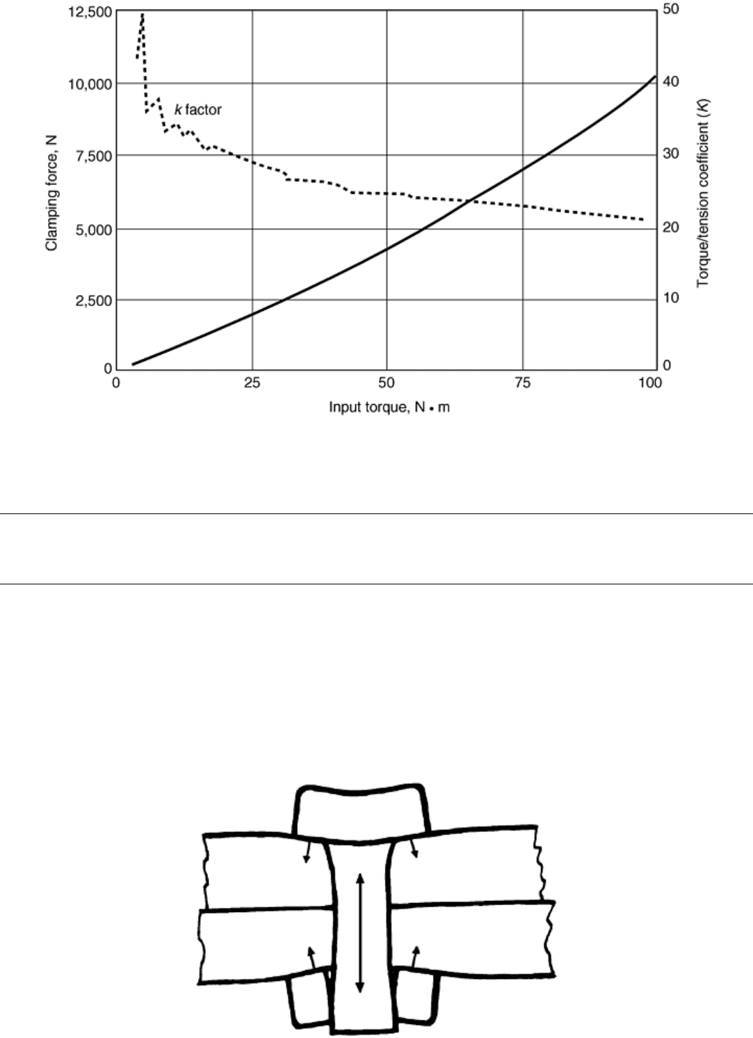
Fig. 20 K-factor plot
Mechanical Testing of Threaded Fasteners and Bolted Joints
Ralph S. Shoberg, RS Technologies, Ltd.
Torque Tension Testing
The amount of tension or clamping force exerted by a fastener when it is tightened is what actually holds the
assembly together. Once the assembly is brought together, the fastener responds like a tension spring, and the
assembly acts like a compression spring. As the fastener is turned and load is applied, the fastener is stretched,
and the parts are compressed. The effect of this interaction between the fastener and the assembly is illustrated
in Fig. 21. This response results in an elastic joint in which the fastener is the flexible member, and the
assembly is the rigid member.
