ASM Metals HandBook Vol. 8 - Mechanical Testing and Evaluation
Подождите немного. Документ загружается.

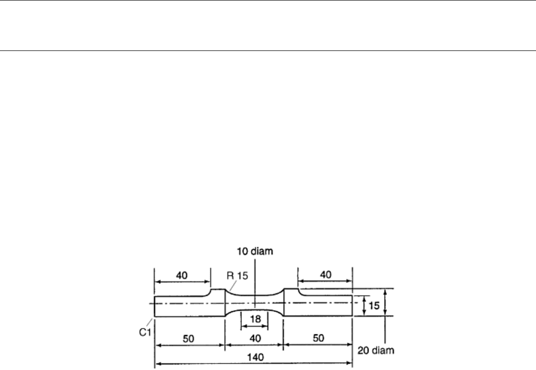
Fig. 3 A semielliptical surface crack under shear. A, pure mode III; B, C, pure mode II
Reference cited in this section
1. Y. Murakami and K. Takahashi, Torsional Fatigue of a Medium Carbon Steel Containing an Initial
Small Surface Crack Introduced by Tension-Compression Fatigue: Crack Branching, Non-Propagation
and Fatigue Limit, Fatigue Fract. Eng. Mater. Struct., Vol 21, 1998, p 1473–1484
Multiaxial Fatigue Testing
Yukitaka Murakami, Kyushu University, Japan
Testing of Cylindrical Specimens
Torsion-Rotating Bending Fatigue. In a classical type of torsion-rotating bending fatigue test, cylindrical
specimens similar to those for rotating bending fatigue are used (Ref 2). A static twisting moment is applied
through the axis of the specimen. In this type of machine, the normal stress in the rotating test piece is
continuously varied between positive and negative stress of equal magnitudes. Furthermore, the steady shearing
stress is simultaneously induced in the specimen by connecting the testing machine with an electric absorption
dynamometer, which consists of a small direct-current dynamo placed on an iron frame suspended by ball
bearing. The specimen geometry for this type of fatigue testing is essentially similar to those for rotating
bending except for the special grip shape. This type of testing machine has still been used in recent studies (Ref
3). In another classical test, bending moment is coupled with twisting moment, which is loaded by the reversed
motion of a fly wheel. The specimen geometry for this test is shown in Fig. 4.
Fig. 4 Specimen for conventional reversed torsion test. Dimensions are in mm. Source: Ref 4
Torsion Coupled with Tension Compression. Biaxial fatigue testing machines of the closed-loop type in which
torsion can be coupled with tension-compression are now commonly used. In the closed-loop type of testing
machine, torsion and tension-compression can be loaded independently in phase or out of phase. Figure 5
shows a biaxial fatigue testing machine of this type. Figure 6 shows the extensometer used to measure axial and
angular displacement. A cylindrical specimen (Fig. 7) is the standard geometry for this type of testing machine.
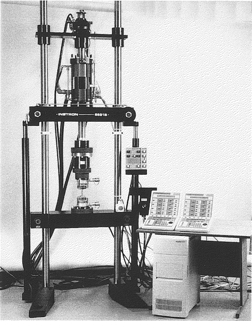
Fig. 5 Biaxial fatigue testing machine. Courtesy of Instron Corporation
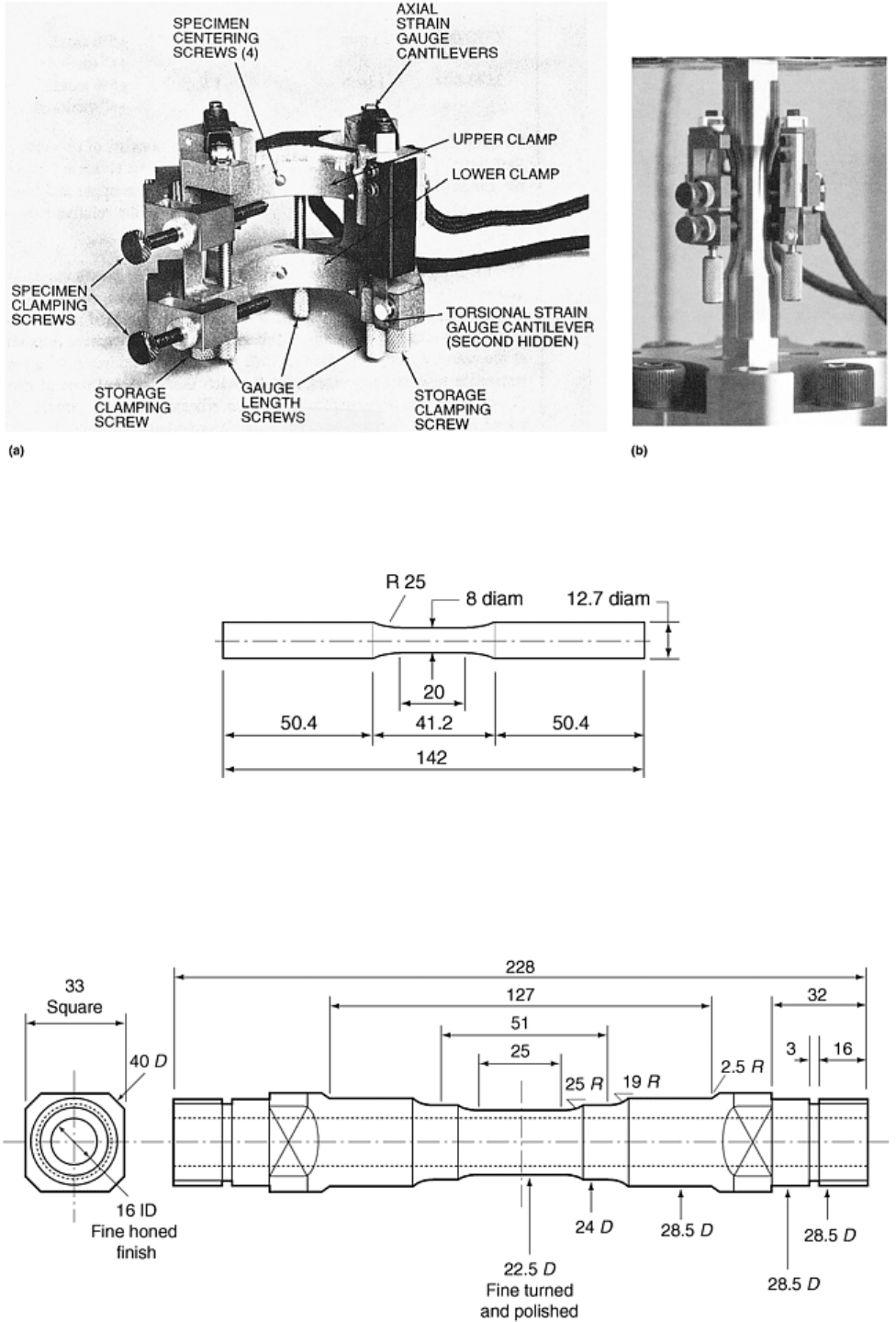
Fig. 6 Biaxial extensometer for simultaneous measurement of axial and torsional strain. (a) Adjustment
screws and clamps. (b) Extensometer mounted on specimen. Courtesy Instron Corporation
Fig. 7 Specimen for biaxial fatigue test. Dimensions are in mm. Source: Ref 1
Triaxial Fatigue Testing. In addition to torsion and tension-compression stresses, internal or external pressures
can be applied to the tubular specimen (Fig. 8). Fatigue behavior in a complex three-dimensional stress
condition then can be studied. However, the operating system of this type of testing machines is very
complicated and expensive. Very few testing machines of this type are available in the world (Ref 5).
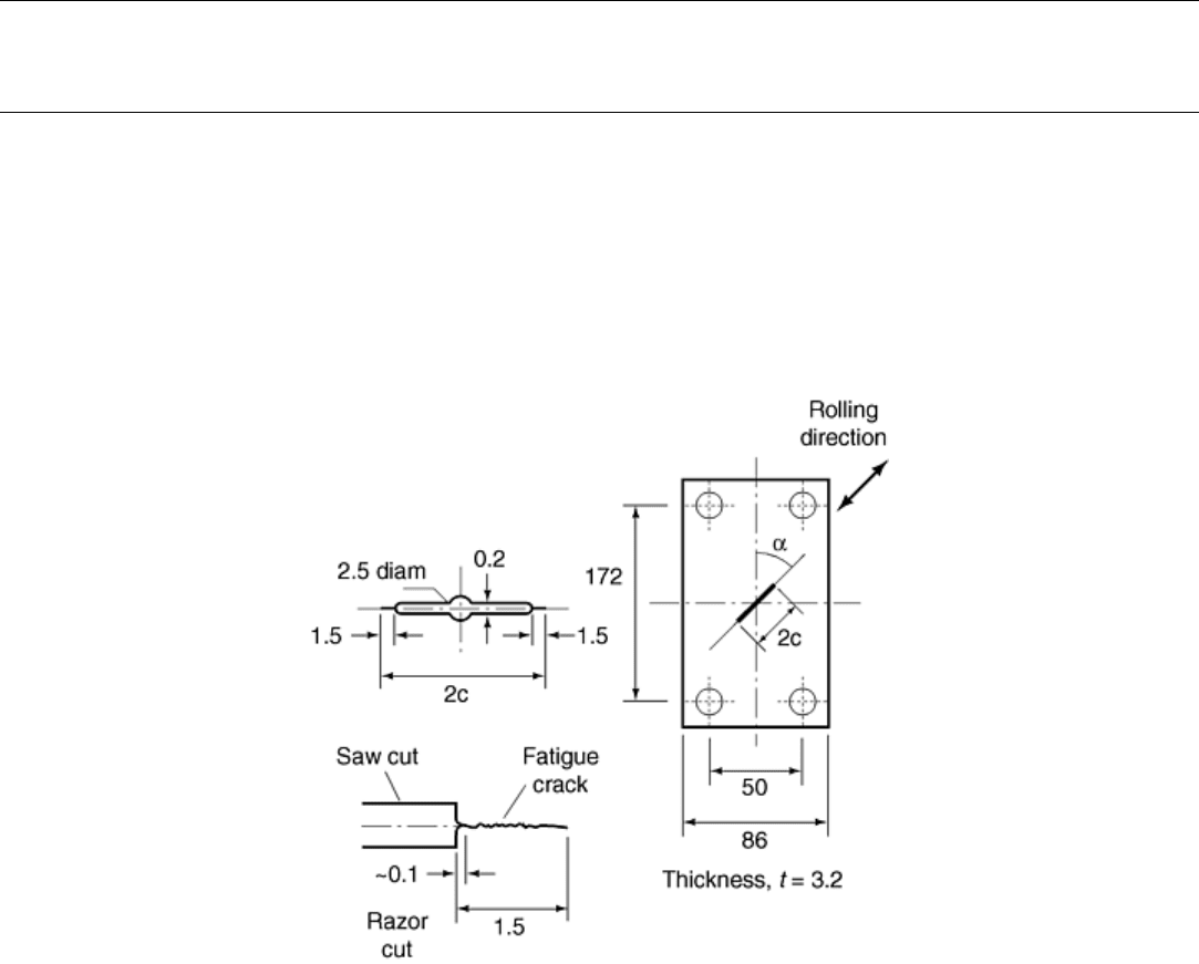
Fig. 8 Tubular specimen for triaxial fatigue test; dimensions are in mm. D, diameter; ID, inside
diameter; R, radius. Source: Ref 5
References cited in this section
1. Y. Murakami and K. Takahashi, Torsional Fatigue of a Medium Carbon Steel Containing an Initial
Small Surface Crack Introduced by Tension-Compression Fatigue: Crack Branching, Non-Propagation
and Fatigue Limit, Fatigue Fract. Eng. Mater. Struct., Vol 21, 1998, p 1473–1484
2. A. Ono, “Fatigue of Steel under Combined Bending and Torsion,” Mem. Coll. Eng., Kyushu Imp.
Univ., Vol 2, 1921, p 117–145
3. M.A. Fonte and M.M. Freitas, Semi-Elliptical Crack Growth Under Rotating or Reversed Bending
Combined with Steady Torsion, Fatigue Fract. Eng. Mater. Struct., Vol 20, 1997, p 895–906
4. M. Endo and Y. Murakami, Effects of an Artificial Small Defect on Torsional Fatigue Strength of
Steels, J. Eng. Mater. Technol. (Trans. ASME), Vol 109, 1987, p 124–129
5. M.W. Brown and K.J. Miller, Biaxial Cyclic Deformation Behavior of Steels, Fatigue Eng. Mater.
Struct., Vol 1, 1979, p 93–106
Multiaxial Fatigue Testing
Yukitaka Murakami, Kyushu University, Japan
Testing of Specimens Containing Notches or Cracks
Rectangular plate specimens containing an inclined central or edge crack are used for crack propagation tests in
mixed-mode loading (Ref 6, 7, and 8). The axial load is applied through the pins attached to the holes at the
grips. A notch or crack is introduced by a saw or razor. If a fatigue crack is introduced in a wide plate by
preliminary tension-compression fatigue, a specimen such as that shown in Fig. 9 can be prepared by cutting
the plate (Ref 6, 7, and 8).
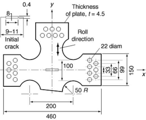
Fig. 9 Rectangular plate specimens containing an inclined center crack. Dimension are in mm. Source:
Ref 7
Cruciform Specimen. The type of specimen shown in Fig. 10 is used to investigate the effect of plastic zone
size or yielding at the tip of a crack. The stress intensity factor has the same value under the combination of an
identical stress, σ
y
, and a different stress, σ
x
. However, the size of the yield zone at the crack tip is dependent on
the value of the stress, σ
x
, in the direction of the crack line.
Fig. 10 Cruciform specimen containing a central crack. Dimension are in mm. Source: Ref 9
Three-Point and Four-Point Bending Specimens with a Crack. In three-point bending (Fig. 11a), not only shear
force but also bending moment is always induced at the crack and, accordingly, we have both K
I
and K
II
. On the
other hand, in four-point bending, one can control the magnitude of bending moment at the crack by changing
the location of loads. This can be done in such a way that there is only a K
II
stress state at the crack tip (Ref 10).
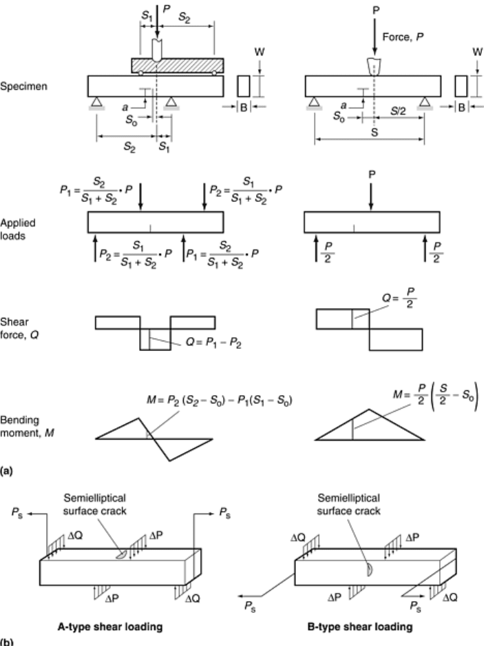
Fig. 11 Three-point and four-point bending specimens, (a) Three-point and four-point bending
specimens with an offset crack. Source: Ref 10. (b) Four-point bending specimens with a semielliptical
edge crack. Source: Ref 11
The specimens shown in Fig. 11(b) are variations of four-point bending specimens with edge cracks (Ref 11).
However, it must be noted that the shear stress component is always zero at the free surface.
Compact Tension Shear Specimen. The compact tension specimen shown in Fig. 12 is used in combination
with a jig that can control the direction of loadings and thus the combination of K
I
and K
II
(Fig. 13) (Ref 12).
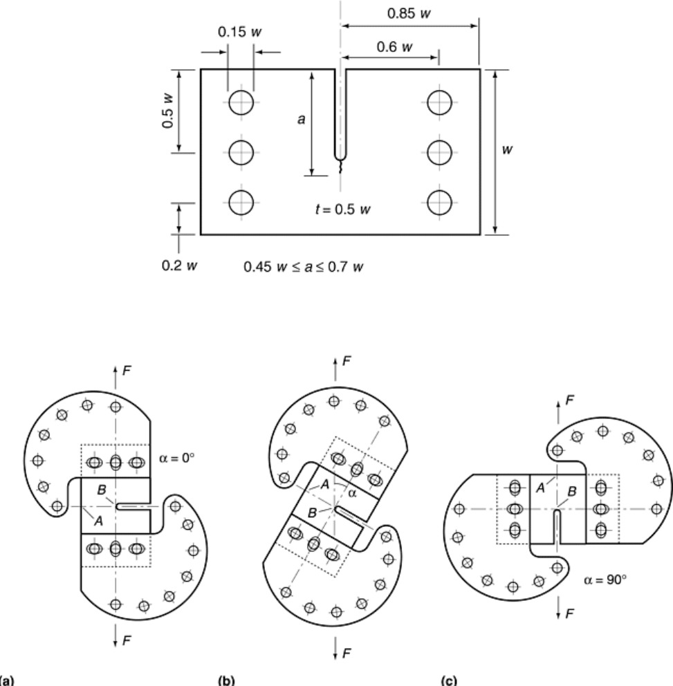
Fig. 12 Shape and dimension of compact tension shear specimen. w, width; t, thickness; a, crack length.
Source: Ref 12
Fig. 13 Position of loading device. (a) Mode I (α = 0°), (b) Mixed mode (0° < α < 90°), (c) Mode II (α =
90°). F, force. Source: Ref 12
Compact Shear Specimen. The compact shear specimen (Ref 13, 14) shown in Fig. 14 is used in the
equilibrium loading system (Fig. 15a), though the mode is not pure mode II. If the distance between the pins of
load application is small, the component of mode I is relatively small compared to the component of mode II.
The specimen of the type in Fig. 15(b) is for the mode III test, but it also has a problem in that the mode I
component is always induced in the system.
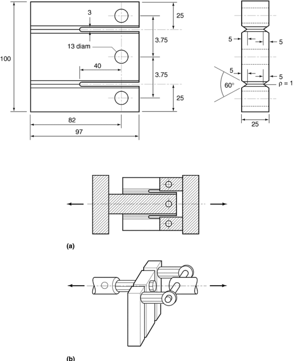
Fig. 14 Shape and dimension of compact shear specimen. Dimension are in mm. ρ, notch root radius.
Source: Ref 14
Fig. 15 Loading apparatus. (a)Mode II type, (b) Mode III type. Source: Ref 14
Mode II Crack Growth Specimen (Ref 15, 16). The mode II threshold stress intensity factor range, ΔK
IIth
, is an
important material property with respect to rolling contact fatigue resistance. However, the measurement of
ΔK
IIth
in the laboratory is very difficult because a crack that has been growing in mode II can easily switch to
mode I growth during the test. A method of measuring ΔK
IIth
has been developed and applied to various steels
(Ref 15, 16).
Figure 16 shows the basic model of measurement method in which a specially designed double-cantilever
specimen is used. Figure 16 shows stress distributions and the normal and shear stress at the position without a
slit. In principle, neither tensile nor compressive stress of σ
x
exists on the neutral axis, and so a mode II fatigue
crack is expected to grow along this section. The specimen (Fig. 17) has a chevron notch and side grooves.
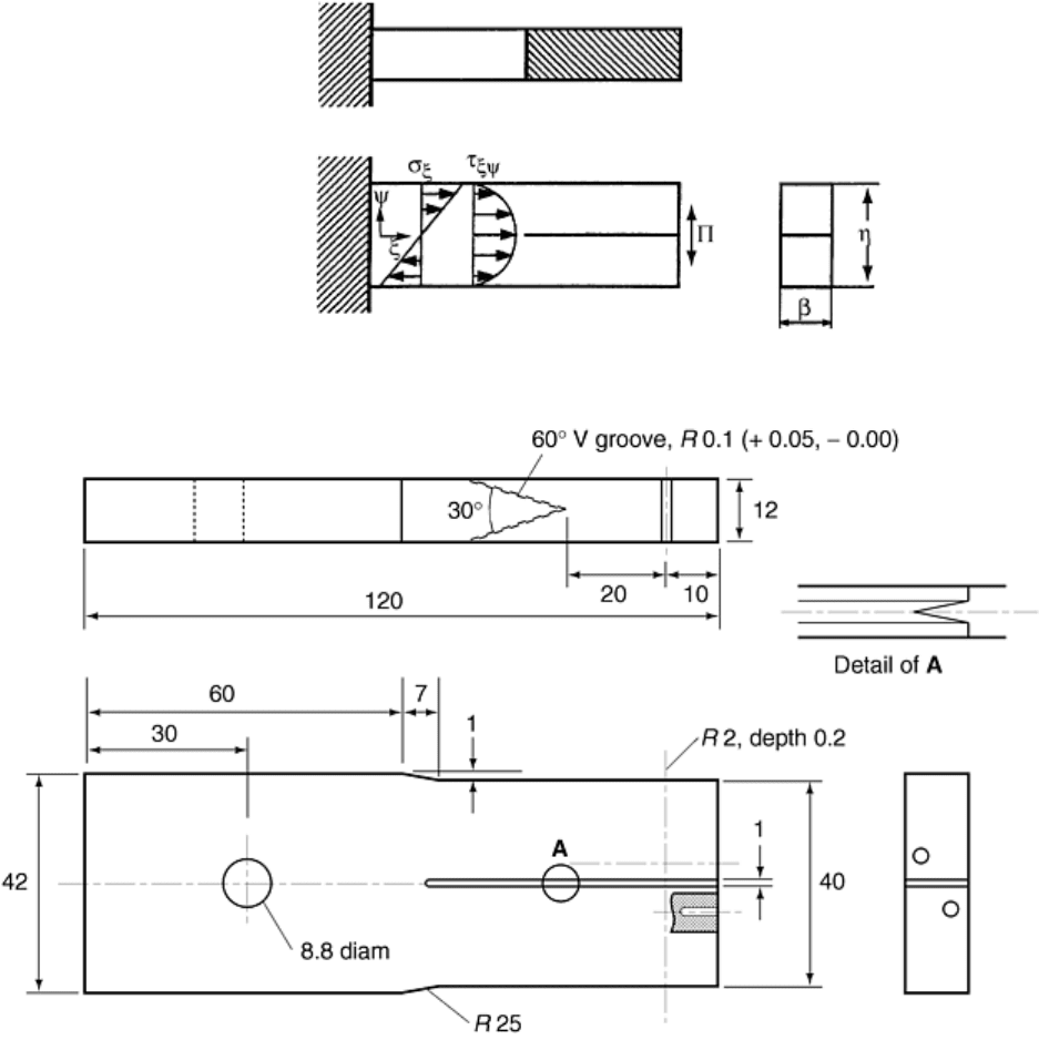
Figure 18(a) shows the setup for the mode II fatigue crack growth test. In this test, two identical specimens are
used as a pair so that a conventional closed-loop type tension-compression servomechanical fatigue machine
can be used. Figure 18(b) shows the detail of attaching one specimen to the testing machine. Ceramic cylinders
are inserted between cantilevers to share the applied load equally to each lever.
Fig. 16 Basic model of mode II crack growth test. P, force
Fig. 17 Shape and dimension of mode II crack growth specimen. Dimensions are in mm
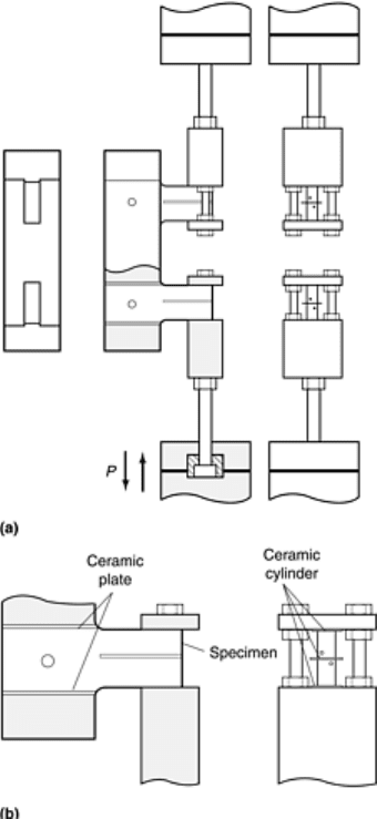
Fig. 18 Mode II crack growth testing machine, (a) Setup of mode II crack growth testing machine. (b)
Detail of mode II crack growth testing machine with one specimen in place
Circumferentially Notched Cylindrical Specimen. This type of specimen is used to investigate the behavior of
mode III crack growth under torsional loading (Fig. 19). Although the nominal stress intensity factor, K
III
, is
known, the exact value is difficult to estimate due to the friction between mating crack surfaces. A typical
morphology of the fracture surface under these conditions is termed “factory roof” morphology (Ref 17).
