ASM Metals HandBook Vol. 8 - Mechanical Testing and Evaluation
Подождите немного. Документ загружается.

interaction (Ref 66, 67). As many as a dozen of the models have survived and have been applied to practical
situations. The three most widely used are the time- and cycle-fraction rule from the ASME Code Case N-47-23
(Ref 68), strain-range partitioning (SRP) (Ref 69) and its total strain version (Ref 70), and continuous damage
mechanics (Ref 71).
The fatigue machines and associated equipment normally used for creep-fatigue experiments are essentially the
same as those used for baseline fatigue tests. Current practice calls for axial loading of a uniform-gage length
specimen mounted in a closed-loop servocontrolled fatigue testing machine with provisions for heating the
sample to elevated temperatures. Closed-loop strain-controlled testing is most commonly used; when it is not
used, strain limit control is imposed to prevent creep ratcheting. The major difference between creep-fatigue
and baseline isothermal fatigue testing is in the time per cycle. To introduce creep into the cycle, the frequency
is reduced by cycling at a lower strain rate or by introducing a hold period at some selected point within each
cycle. Most commonly, a hold period is inserted at the peak strains in a cycle, that is, at maximum or minimum
algebraic strains, or at both peaks.
Creep-fatigue interaction testing is conducted at a high enough isothermal temperature that thermally activated,
diffusion-controlled creep deformation mechanisms can operate under stress as a function of both time and
temperature. As a rough rule of thumb, the transition temperature for creep is on the order of half the absolute
melting temperature of an alloy. In earlier years, creep-fatigue testing was conducted to simply ascertain the
extent of the damaging effect of creep on cyclic (fatigue) life. Today, tests are still run for that purpose, but
more often than not, creep-fatigue testing is designed also to evaluate and calibrate the constants in a viable
creep-fatigue life prediction model.
The addition of creep to a cycle of normal fatigue loading will invariably reduce the cyclic life, although the
clock time to failure may remain constant or actually increase. Conversely, the superposition of fatigue cycling
and conventional monotonic creep will also alter the rate of creeping and the time to rupture. Because of the
importance placed on knowing the values of stress and time-dependent deformation, it is generally regarded
that creep-fatigue testing be done with axially loaded specimens equipped with extensometry. While some
interspersed creep-fatigue testing, that is, repeated blocks of brief periods of creep followed by brief periods of
fatiguing, has been reported (Ref 62), the most common tests involve repeating cycles of straining with hold
periods imposed in tension or compression alone or in combination. The hold periods may be under constant
strain or constant stress. If under constant stress, strain limits are generally imposed to preclude ratcheting.
Alternatively, creep could be introduced by controlled slow straining rates in tension, compression, or both.
Figures 28 illustrates the various isothermal hysteresis loops that are commonly encountered in fatigue and
creep-fatigue testing. Figures 28(a), 28(e), 28(f), and 28(g) were used to generated the data shown in Fig. 29 for
AISI type 304 stainless steel (Ref 67). Here the inelastic strain range is plotted against cycles to failure on log-
log coordinates. As can be seen, significant cyclic life losses (a factor of 10 or more) are possible with strain
hold periods of just 30 minutes per cycle in tension only. Hold periods of up to 180 minutes per cycle do not
necessarily further reduce the cyclic life, implying a saturation condition beyond a certain hold period for strain
hold (stress relaxation) creep-fatigue cycles. Those cycles that are balanced in nature, that is, the tensile and
compressive halves experience the same strain rates or hold times, will not exhibit an algebraic mean stress,
whereas the unbalanced cycles will. The mean stress is tensile if the hold period or slow straining rate is in
compression and vice versa. Evidence suggests that these mean stresses do not exhibit the classical mean stress
effect on cyclic life in the high-strain range, low-cycle fatigue regime (Ref 54), and hence can be ignored.
Similar creep-fatigue cycling results for AISI type 304 stainless steel and Incoloy 800 have been reported in
Ref 72. These results were analyzed in Ref 73 by both the time- and cycle-fraction rule and the method of
strain-range partitioning based on information provided in Ref 72.
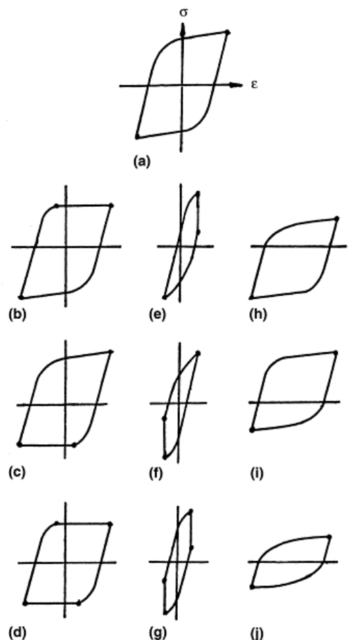
Fig. 28 Schematic hysteresis loops encountered in isothermal creep-fatigue testing. (a) Pure fatigue, no
creep. (b) Tensile stress hold, strain limited. (c) Compressive stress hold, strain limited. (d) Tensile and
compressive stress hold, strain limited. (e) Tensile strain hold, stress relaxation. (f) Compressive strain
hold, stress relaxation. (g) Tensile and compressive strain hold, stress relaxation. (h) Slow tensile
straining rate. (i) Slow compressive straining rate. (j) Slow tensile and compressive straining rate
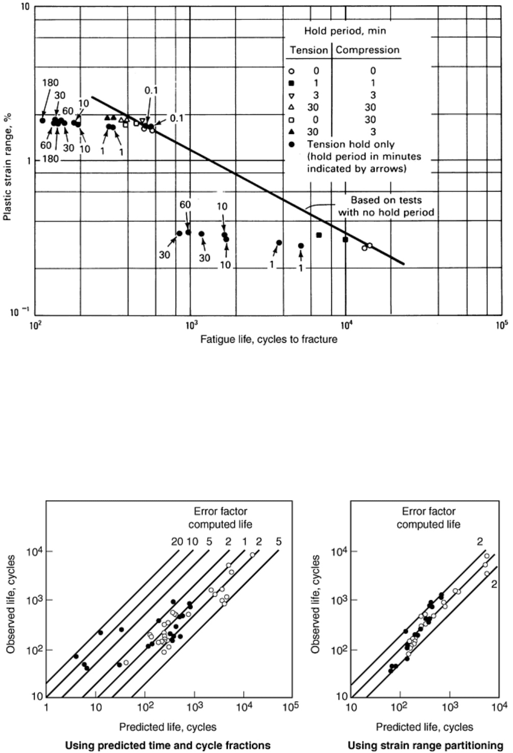
Fig. 29 Creep-fatigue interaction effects on isothermal cyclic life of AISI type 304 stainless steel tested in
air at 650 °C (1200 °F), normal straining rate of 4 × 10
-3
s
-1
. After Ref 65
Comparison of the two creep-fatigue life prediction models is given in Fig. 30. In this instance, the time- and
cycle-fraction rule, which utilizes a stress-based approach to assessing creep damage, does not do an acceptable
job of predicting the laboratory results. Cyclic lives can be over-predicted by as much as a factor of 5 and
under-predicted by a factor of 20, thus creating a band of uncertainty in predicted life of two orders of
magnitude. The method of strain-range partitioning is a strain-based approach and assigns creep damage
according to the magnitudes of the creep strains encountered in a cycle. The figure indicates a strain-based
approach is superior in this case.

Fig. 30 Predictability of creep-fatigue lives for tensile strain hold time cycles for Incoloy 800 and AISI
type 304 stainless steel at elevated temperatures. Source: Ref 70, 71
A viable creep-fatigue model is of great importance to be able to design equipment to operate for long periods
of time at elevated temperature. Services lifetimes are typically much greater than the longest affordable creep-
fatigue testing lifetimes of laboratory specimens. What a viable model has to offer is increased confidence in
the extrapolations to longer times to failure than were used in the model calibration. A physically based model
is expected to hold greater promise than simple empirical extrapolation of noncorrelated laboratory data.
Because laboratory creep-fatigue measurements are the basic ingredients of the foundation for assessing
extrapolated long-time structural durability, it is imperative that accurate measurements and control of the
testing variables be maintained. The problem is a much more stringent one than for lower-temperature, fatigue-
life extrapolation because of the influence of time and temperature. Creep is sensitive to temperature in a highly
nonlinear exponential dependency and sensitive to stress and time of exposure in nonlinear power-law
dependencies. The temperature and time dependencies also include the effects of interaction with the
environment. Typically, oxygen is the surrounding environment and surface oxidation can greatly influence the
susceptibility of exposed surfaces to premature crack initiation and early growth. Most creep-fatigue models are
calibrated and used without the benefit of separating the effects of oxidation from the creep effects. A listing of
models with the potential for accounting specifically for oxidation or other environmental interaction effects is
found in (Ref 67).
Creep-fatigue test results are generally more extensive than simpler fatigue results. Table 5 lists, among other
items to be discussed, the additional information that should typically be reported for each creep-fatigue test
conducted.
Table 5 In-test and post-test information guidelines for creep fatigue and thermomechanical fatigue
Cyclically varying
parameters
Value of fixed test control parameters (stress, strain, temperature, temperature and
straining rates, hold times, phasing relation between temperature and strain, as
applicable); continuous recording of variations of maximum, minimum, amplitude,
range, and mean values of stress, strain, and temperature as a function of applied
cycles (or sufficient information for calculation of these parameters); cyclic variation
of load range ratio of tensile to compressive peak loads (under strain control) and
cyclic variation of strain range and ratio of maximum to minimum strain peaks
(under load control) to help define failure life and hence half-life; continuous or
periodic recording of variations of stress-strain hysteresis loops and stress versus
time and strain versus time; any parameter deemed necessary for evaluation of a
particular creep-fatigue or thermomechanical fatigue model (e.g., for strain range
partitioning, the amounts of tensile and compressive creep and plastic strains)
Lifetime
information
Cyclic failure lives based on various cyclic failure criteria; failure life (cycles and
corresponding time) for criterion adopted; half-life cycles; total, inelastic (partitioned
strain ranges and method of partitioning if using strain range partitioning), and
elastic strain ranges at half-life; maximum, minimum, stress amplitude, stress range,
mean stress, and mean stress ratio at half-life; degree of cyclic hardening and/or
softening from first cycle to half-life (or cycles at stabilization of stress-strain
response); description of fracture surface including initiation site(s); degree of
transgranular and intergranular cracking; location of fracture relative to
extensometer probes
Deviations from
original test plans
Details of stress and strain history and temperature immediately prior to controlled
or uncontrolled shut-downs prior to test completion
Data analysis
from multiple
specimens
Cyclic stress-strain curve and how it varies with strain rate, frequency, cycle time,
hold time, and temperature; equation constants at half-life (or cycles at stabilization),
that is, the cyclic flow properties; fatigue curves, creep-fatigue curves, and
thermomechanical fatigue curves expressed in terms of inelastic strain range, total
range, and elastic strain range versus cyclic life; equation constants and how they
vary with temperature and some measure of testing time, that is, the cyclic failure

properties
References cited in this section
54. M. Doner, K.R. Bain, and J.H. Adams, Evaluation of Methods for Treatment of Mean Stress Effects on
Low-Cycle Fatigue, J. Eng. Power (Trans. ASME), Vol 104, 1982, p 403–411
62. R.M. Curran and B.M. Wundt, Continuation of a Study of Low-Cycle Fatigue and Creep Interaction in
Steels at Elevated Temperatures, 1976 ASME-MPC Symposium on Creep-Fatigue Interaction, Materials
Property Council MPC-3, American Society of Mechanical Engineers, 1976, p 203–282
63. S.S. Manson, Critical Review of Predictive Methods for Treatment of Time-Dependent Metal Fatigue at
High Temperatures, Pressure Vessels and Piping: Design Technology—1982—A Decade of Progress,
American Society of Mechanical Engineers, 1982, p 203–225
64. D.A. Miller, R.H. Priest, and E.G. Ellison, A Review of Material Response and Life Prediction
Techniques under Fatigue-Creep Loading Conditions, High Temp. Mater. Process., Vol 6, 1984, p 155–
194
65. V.M. Radhakrishnan, Life Prediction in Time Dependent Fatigue, Advances in Life Prediction Methods,
American Society of Mechanical Engineers, 1983, p 143–150
66. G.R. Halford, Evolution of Creep-Fatigue Life Prediction Models, Creep-Fatigue Interaction at High
Temperature, G.K. Haritos and O.O. Ochoa, Ed., Vol 21, American Society of Mechanical Engineers,
1991, p 43–57
67. G.R. Halford, Creep-Fatigue Interaction, Heat Resistant Materials, ASM International, 1997, p 499–517
68. Code Case N-47-23, American Society of Mechanical Engineers, 1986
69. S.S. Manson, G.R. Halford, and M.H. Hirschberg, Creep-Fatigue Analysis by Strain-Range Partitioning,
Symposium on Design for Elevated Temperature Environment, American Society of Mechanical
Engineers, 1971, p 12–28
70. J.F. Saltsman and G.R. Halford, “An Update on the Total Strain Version of SRP,” ASTM STP 942, Low
Cycle Fatigue—Directions for the Future, H.D. Solomon, G.R. Halford, L.R. Kaisand, and B.N. Leis,
Ed., American Society for Testing and Materials, 1988, p 329–341
71. J.-L. Chaboche, Continuous Damage Mechanics: A Tool to Describe Phenomena before Crack
Initiation, Nucl. Eng. Des., Vol 64, 1981, p 233–247
72. C.E. Jaske, H. Mindlin, and J.S. Perrin, “Combined Low-Cycle Fatigue and Stress Relaxation Behavior
of Alloy 800 and Type 304 Stainless Steel at Elevated Temperatures,” ASTM STP 520, Fatigue at
Elevated Temperature, American Society for Testing and Materials, 1973, p 365–376
73. S.S. Manson, “The Challenge to Unify Treatment of High Temperature Fatigue— A Partisan Proposal
Based on Strain-Range Partitioning,” ASTM STP 520, Fatigue at Elevated Temperature, American
Society for Testing and Materials, 1973, p 744–782

Fatigue, Creep Fatigue, and Thermomechanical Fatigue Life Testing
Gary R. Halford and Bradley A. Lerch, Glenn Research Center at Lewis Field, National Aeronautics and Space Administration; Michael
A. McGaw, McGaw Technology, Inc.
Thermomechanical Fatigue
Thermal fatigue is a structural failure mode in many high-temperature components. Thermal fatigue loading is
induced by temperature gradients during transient heating or cooling from one high temperature of operation to
another. Thermal fatigue loading can also occur when heating and cooling are present simultaneously and
thermal gradients are maintained during steady-state operation. Internally air-cooled high-temperature turbine
blades are examples. Thermal gradients produce differential expansion as the hottest material wants to expand
more than the cooler, but is constrained from doing so by the cooler and stronger material. The constraint is
perceived by the hottest material as a compressive thermal strain that is no different in its effect on the material
than would be a mechanically induced strain of equal magnitude. Similarly, the coldest material is forced by the
hottest to expand more than normal. The thermally induced strain in the colder material is tensile. Conditions of
strain compatibility will be maintained. The corresponding thermal stresses result directly from the thermal
strains according to the current stress-strain relation and the necessity to obey the laws of equilibrium. The
integrated sum of the internal stresses into forces must always equal zero. Because of the gradients of the
primary variables, it is impossible to measure the thermal fatigue properties of a material in the same way that
isothermal fatigue or creep-fatigue properties are measured, that is, in terms of holding certain variables
constant while the response of the others are measured. To overcome this basic difficulty, TMF tests have been
devised.
Thermomechanical Fatigue Testing. The testing machine and specimen set up for TMF testing are essentially
the same as used for creep-fatigue testing or baseline high-temperature isothermal fatigue testing. The major
distinction is that the temperature of the specimen, instead of remaining constant, must be programmed to vary
in a precisely defined manner. Furthermore, the cycling rate must, at times, be rather high, requiring the ability
to heat and cool the test specimen as rapidly as possible without creating undue thermal gradients. This
requirement virtually rules out the use of conventional clamshell radiation furnaces because of their large
thermal inertia. Most commonly, induction heating is used. This is because of the reasonably high rates of
heating possible, and because the temperature gradient along the specimen gage length can be controlled better
with a three-zone induction heating coil arrangement, as shown in Fig. 11. Induction coils are also more
conducive for use of extensometers. Direct resistance heating, although not commonly used, has the capability
of heating a sample so rapidly that it could be melted in a matter of seconds. Heating is usually not the limiting
factor in governing the cycling rate, rather, cooling is. Forced air cooling has been used successfully. Jets of air
are impinged on the specimen surface along the gage length and around the circumference. Excessive cooling
induces thermal gradients and, hence, unwanted thermal stress and strains. A balance must be achieved between
cooling (as well as heating) rate and the extent of undesired thermally induced stresses and strains. Thermal
cycling rates as fast as 3 minutes per cycle are employed on a routine basis. A test run to 12,000 cycles requires
36,000 minutes or 600 hours. This is without consideration of a hold period at the peak temperature. A testing
program involving dozens of specimens could thus become extremely expensive and time consuming. Cycling
rates as high as 20 seconds per cycle have been achieved through diligence. However, the thermal gradients are
quite high and control of the temperature and strain is poor, although reproducible.
Raising the minimum temperature in the laboratory TMF cycle is a commonly used approach to help speed up
TMF testing frequency. This can considerably reduce the time needed to cool because cooling follows an
exponential decay curve. Removing the last portion of that curve can significantly decrease the cooling time per
cycle. However, the range of temperature is reduced in the process, and the measured TMF characteristics are
removed further from what occurs in most applications. For most industrial equipment, the minimum
temperature in a thermal fatigue cycle is ambient, and is considerably below the minimum temperature usually
selected for TMF testing. Normally, the testing conditions of temperature range, minimum temperature, and
cycling rate are determined by compromise. Regardless of the minimum temperature selected for testing, there
remains the desire to shorten the time per cycle; this leads to higher thermal gradients throughout the test
specimen.
Of course, one of the purposes of TMF testing is to intentionally keep thermal gradients negligibly small while
the overall temperature of the test volume of the specimen is raised and lowered cyclically. Simultaneously, the
magnitude of the uniformly distributed strains (stresses) in the specimen is controlled independently of the
temperature change, although a fixed phasing is usually maintained between them. As a consequence, the test
specimen could be programmed to experience cyclic thermal and mechanical strains just as the material might
at a critical point were it undergoing thermal fatigue in a structural element. In this way, the resistance of a
material to thermal fatigue can be experimentally evaluated for a range of phasings and amplitudes of strain
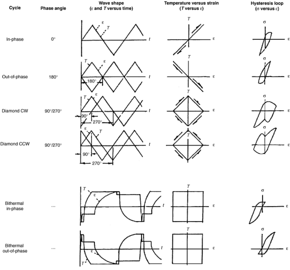
(stress) and temperature. Figure 31 illustrates a series of basic TMF strain cycles for the most rudimentary of
TMF situations in which mechanical strain and temperature vary in lock step with one another. A triangular
waveform is used for the example cycles, although sinusoidal, is also in vogue. When the same waveform is
used for both strain and temperature, their time phase shift can be described by a single parameter, the phase
angle. In-phase cycling (0 ° phase shift) is defined as having the maximum algebraic strain occur at the same
instant as the maximum temperature and having the minimum algebraic strain occur at the minimum
temperature. Out-of-phase TMF cycling (180 ° phase shift) is just the reverse of in-phase cycling. A phase
angle of 90 ° or 270 ° corresponds to a diamond-shaped (sometimes referred to as baseball) pattern of
mechanical strain versus temperature. The resultant stress-strain hysteresis loop for a diamond cycle will appear
as unusual because the maximum and minimum temperatures do not occur at the maximum or minimum
mechanical strain. These and other basic cycles (bithermal) to be introduced later serve as excellent uniform
types of cycles for characterizing the TMF fatigue resistance of materials.
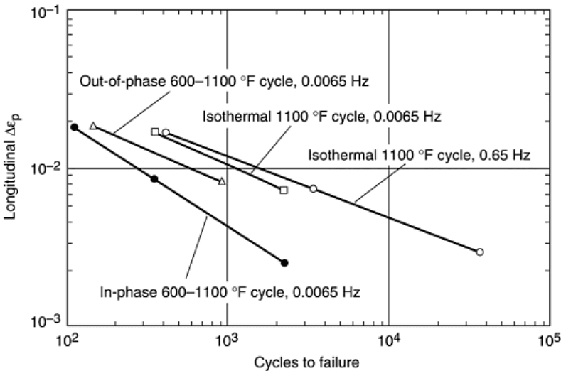
Fig. 31 Basic thermomechanical fatigue strain cycles
Rarely, however, are the simple cycles discussed above encountered exactly in service. Because TMF fatigue
life is generally wave-shape dependent, means are required to generalize laboratory characterizations so they
may be applied to any unique thermal fatigue cycle encountered in service. This is usually accomplished with a
life prediction model. Again, physically based models will have the greatest potential for proper interpolation
and extrapolation of results generated. There are spectra of TMF tests of any given type of cycle that could be
conducted in a laboratory: phasings could cover the range from in phase to out of phase and all points between,
as well as for TMF cycles that are not describable, by quoting a simple measure of phasing; temperature ranges
could be very narrow or very wide; the maximum and minimum temperatures could also cover a broad range,
as could the mechanical strain range. The frequency (or other measure of the cycling rate and hold periods) is
yet another critical variable to be investigated if one is to document the broad range of the thermal fatigue
resistance of a material. A complete test matrix that could capture all of the pertinent variables is too large to be
practical. Judicious selection of the variables and their combinations and ranges is usually required based on the
potential application of the results. ASTM committee E-08 on fatigue is currently crafting a standard for basic
TMF fatigue testing (Ref 74) involving simple waveforms (e.g., triangular, sinusoidal) of phased strain and
temperature cycling. Once approved and published, the standard will be a valuable document to consult before
conducting TMF tests. Table 5 lists in-test and post-test information that should be documented for each TMF
test conducted.
As discussed in the reviews of Ref 75, 76, and 77, the thermal fatigue resistance of a material is not necessarily
derivable from isothermal fatigue resistance, and it is frequently lower than isothermal fatigue resistance. This
is generally observed despite comparisons made to isothermal fatigue resistance measured at the maximum
TMF test temperature (i.e., usually thought to be the lowest isothermal fatigue resistance within the span of the
TMF temperature range). The basis for comparison of isothermal and TMF fatigue resistance of a material is
also important. For example, the TMF resistance may be poorer if the inelastic strain range is used as the basis
of comparison, but could be better if the total strain range is used. This apparent dichotomy is a direct result of
the differences in the cyclic stress-strain behavior between isothermal and TMF cycling. Comparisons of
isothermal and TMF fatigue resistance to inelastic strain for two example alloys (Ref 78, 79) are shown in Fig.
32 and 33.
Fig. 32 Comparison of isothermal and thermomechanical fatigue resistance of A 286 precipitation-
hardening stainless steel. Source: Ref 76, 77, 78
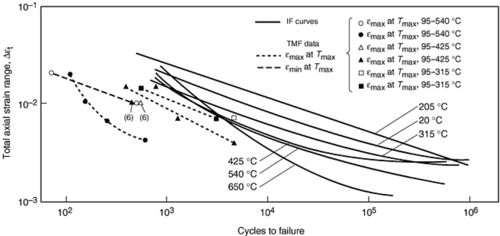
Fig. 33 Comparison of isothermal and thermomechanical fatigue resistance of AISI 1010 carbon steel.
Source: Ref 76, 77, 79
Thermomechanical Fatigue-Life Modeling. Because of the large number of variables and the inherent problem
of not being able to afford to test for all possible combinations of variables, alternate approaches are desirable.
One attractive approach is to adopt a TMF life prediction method. By calibrating the constants in equations
representing the model, the means are available to calculate behavior under other conditions by interpolation
and extrapolation. A variety of TMF life prediction models are discussed in Ref 67, 73, 76, and 77. Among the
more frequently used models are the ASME time- and cycle-fraction rule (Ref 68), the continuum damage
model of ONERA (the French space agency) (Ref 71), the University of Illinois creep-fatigue-oxidation model
(Ref 80, 81), and the NASA Glenn (formerly Lewis) method of strain-range partitioning (SRP) (Ref 82).
The SRP approach for creep-fatigue and TMF life prediction takes advantage of bithermal fatigue testing (Ref
83). As the name implies, bithermal cycling is conducted using two isothermal temperatures within each cycle.
The high isothermal temperature represents the maximum temperature of a more complex TMF cycle, while the
low isothermal temperature represents the minimum. The impetus for developing bithermal testing was to
permit direct measurement of both thermal expansion strain and mechanical strain without them being
intermixed. Visual observation of a bithermal hysteresis loop unequivocally identifies these two types of strain.
During conventional TMF cycling, thermal and mechanical strains are applied simultaneously and can only be
separated by calculation. During bithermal cycling, mechanical straining (and stress) is applied only during the
two isothermal halves and not when the temperature is being changed. The stress on the specimen is controlled
at zero during any change in temperature, thus providing a clear separation of thermal expansion and
mechanical strains.
A schematic bithermal hysteresis loop is shown in Fig. 34. An out-of-phase cycle is shown. All tensile
mechanical straining is done at the low temperature, and compressive mechanical straining is done at the high
temperature. The loading sequence in traversing a cycle is noted in the table to Fig. 34. The tensile loading from
point A to B and unloading from B to C is done at the cold temperature where the elastic modulus is E
cold
. It is
presumed the temperature is low enough and the straining rate is high enough that time-dependent creep is
precluded and only plasticity occurs. Hence, the tensile inelastic (plastic) strain is AC and the corresponding
elastic strain is CB′, that is, stress at B divided by E
cold
. At point C the load is held at zero and the specimen
temperature raised to the hottest temperature where the elastic modulus is E
hot
. The specimen expands freely
from C to D, a direct measure of the thermal expansion strain over the temperature range. Once thermal
stability has been attained, the specimen is strained rapidly into compression until a predetermined stress is
reached at point E. The inelastic strain DE″ is time-independent plastic strain. Under the stress at E,
compressive creep occurs until the strain limit at point F is reached and the specimen is rapidly unloaded to
point G. The amount of compressive creep strain is EF, and the compressive inelastic strain is DG = DE″ + EF
(or E″G). The corresponding compressive elastic strain is the creep stress (along EF) divided by E
hot
. Cooling
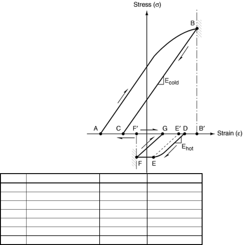
from point G to point A completes the bithermal loop. The thermal contraction GA should be equal to the
expansion CD.
Strain
Type of strain Temperature
Action
AB Elastic + plastic Low
Rapid straining
BC Elastic unloading Low
Rapid straining
CD Thermal expansion Low-high
Zero stress
DE Elastic + plastic High
Rapid straining
EF Creep High
Constant stress
FG Elastic unloading High
Rapid straining
GA Thermal constraction
High-low Zero stress
Fig. 34 Schematic bithermal hysteresis loop (out-of-phase cycle)
It is simple to interpret directly from the hysteresis loop of Fig. 31 the magnitudes of the elastic strains, the
inelastic strains, the total strains, and the thermal expansion strains. It is much more difficult to determine these
parameters from a continuously varying TMF hysteresis loop. The elastic strain range for the bithermal loop is
the sum of the absolute values of the tensile and compressive elastic strains. The corresponding inelastic strain
range is the width of the hysteresis loop at zero stress. There are two measures of this strain range, AC or DG.
Theoretically, they must be equal; otherwise, cyclic ratcheting takes place. However, the fixed strain limits
prevent ratcheting. Since every experimental measurement has some scatter, it is recommended that AC and
DG be averaged to determine the value of the inelastic strain range. The total strain range of the bithermal loop
is the sum of the elastic and inelastic strain ranges. The loop also reveals the partitioning of the inelastic strains
into its creep and plasticity components for use in the strain-range partitioning method for life prediction. An
in-phase bithermal hysteresis loop would look just like the out-of-phase loop, except that the loop would be
mirror imaged about the strain axis. Thermal fatigue cycles experienced in service rarely have high enough
temperatures in both the tensile and compressive halves to suffer creep strains in both directions. Even the 90°
or 270° diamond-type cycles tend to experience creep strains predominately in tension or compression only. If,
however, the total strain range is very large, all TMF cycles will experience reversed creep. Such cycles rarely,
if ever, occur in service situations and are an artifact of TMF testing in the laboratory. By contrast, bithermal
tests, for any magnitude of strain range, can be devised that do not experience reversed creep.
Commercially available software is available to conduct bithermal tests on a routine basis using computer
control.
