ASM Metals HandBook Vol. 17 - Nondestructive Evaluation and Quality Control
Подождите немного. Документ загружается.

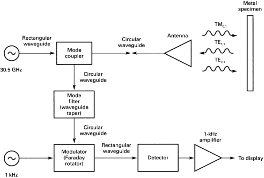
Fig. 31 Mode-converting crack-detection system. Source: Ref 30
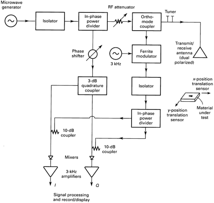
Fig. 32 Microwave system for measuring cross-polarized backscatter using homodyne detection. Source:
Ref
31
An earlier microwave crack detection scheme is shown in block diagram form in Fig. 30. It is a basic reflectometer with
two additional features. The first one is a microwave bridge to null out the background signal (that is, the surface
reflection). The second is a rotating waveguide joint that provides polarization of the incident wave. This effectively tags
the signal scattered by the crack because the crack is a polarizing filter that scatters maximum when the incident electric
field is perpendicular to the length of the crack (Ref 29). This is a type of mode conversion in which the crack converts a
fraction of the incident wave (a mode) into an orthogonally polarized wave (an independent mode).
Another system of mode conversion is used in the microwave crack detection system given in Fig. 31. The diameter of
the circular waveguide connecting the mode coupler to the horn antenna is chosen so that either the TM
01
or the TE
01
circular waveguide mode is excited and radiated. The horn is placed close to the sample so that the incident fields at the
sample surface are essentially those of the waveguide mode. A crack in the surface converts some of the incident energy
to the TE
11
mode, which is separated from the other modes with a tapered waveguide and a Faraday-rotor modulator.
The block diagram of the third microwave eddy current detection system is given in Fig. 32. It also uses mode conversion
but without polarization modulation (Ref 31). A linearly polarized incident wave is partially converted to orthogonal
polarization when the incident polarization is at an angle of 0 to 90° relative to the slot (crack) (Ref 31). The homodyne
detection system provides outputs that are in-phase (I) and quadrature-phase (Q) and that can be displayed in the same
way as the conventional (low-frequency) eddy current system.
The antenna used in the system was a lens-focused horn with a beam width at its focal point of about 3.5 mm (0.14 in.) at
the operating frequency of 100 GHz. This is an example of a radiating probe that searches for flaws in the far field.
The results from the three systems reported indicate that the crack is detectable provided that the crack is open, the crack
has a high Q, and the crack length is larger than one-half wavelength (Ref 31). In practice, one would vary the frequency
until the crack signal is normal to the lift-off circle. Knowing the frequency and having a model for the electromagnetic
propagation within the crack, the depth could be determined. This feature is self-calibrating because the phase of the
crack signal is measured relative to the lift-off circle. (The lift-off signal roughly follows a circular path on the
oscilloscope. This path is called the lift-off circle. The diameter of the lift-off circle depends on the system gain.)
Microwave eddy current systems have also been built using planar transmission lines rather than waveguides so that they
are of the near-field type. This probe has a higher sensitivity than the others in Fig. 30, 31, and 32. The probes use a pair
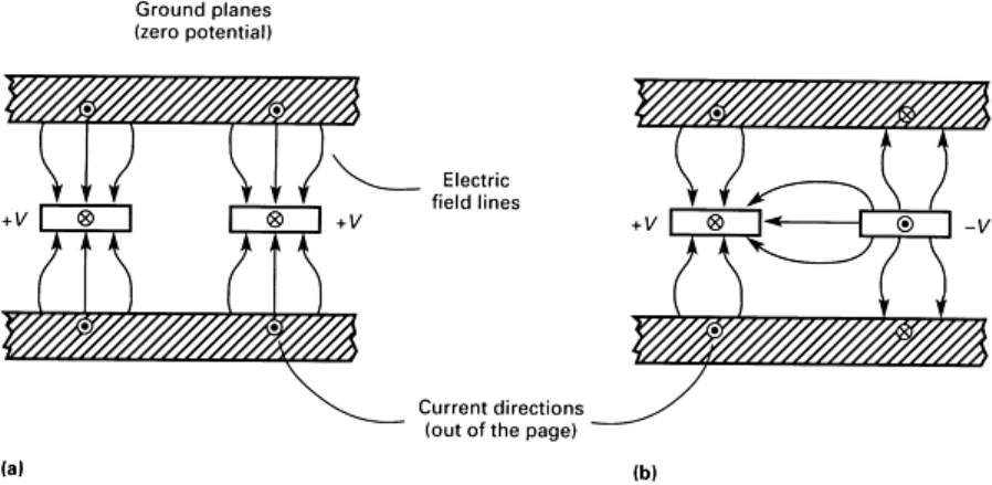
of adjacent coupled striplines, as shown in Fig. 33. The coupled striplines can support two orthogonal TEM modes, the
even (Fig. 33a) and the odd (Fig. 33b). The direction of propagation is perpendicular to the plane of Fig. 33. For the even
mode, the two strips are at the same potential relative to ground. For the odd mode, the potentials with respect to ground
have potentials that are of the same magnitude with respect to ground but of opposite polarity. The strips carry opposite
but equal currents.
Fig. 33 Two orthogonal modes for a pair of coupled striplines (support dielectric not shown).
(a) Even mode.
(b) Odd mode. Source: Ref 32
In the even mode, there will be no conversion to the odd mode as long as symmetry is maintained. However, when a
surface crack in one ground plane perturbs the current under one strip but not the other, some power will be converted to
the odd mode. Such a pair of coupled-strip transmission lines can be used as a crack detector if the surface to be inspected
is one of the ground planes, if the strips are excited in the even mode, and only if the odd mode is detected. This type of
probe depends on mode conversion to achieve a high sensitivity, as have the ones discussed previously.
A cross section of the probe used to inspect 175 mm shells is shown in Fig. 34. Two important features of the stripline
probe are as follows:
• The striplines can be as long as desired
•
The stripline probe can be made to conform to a curved surface if thin, flexible dielectric substrate is
used
In Fig. 34, the shell body forms one ground plane of the strip transmission line as is necessary for detecting open cracks.
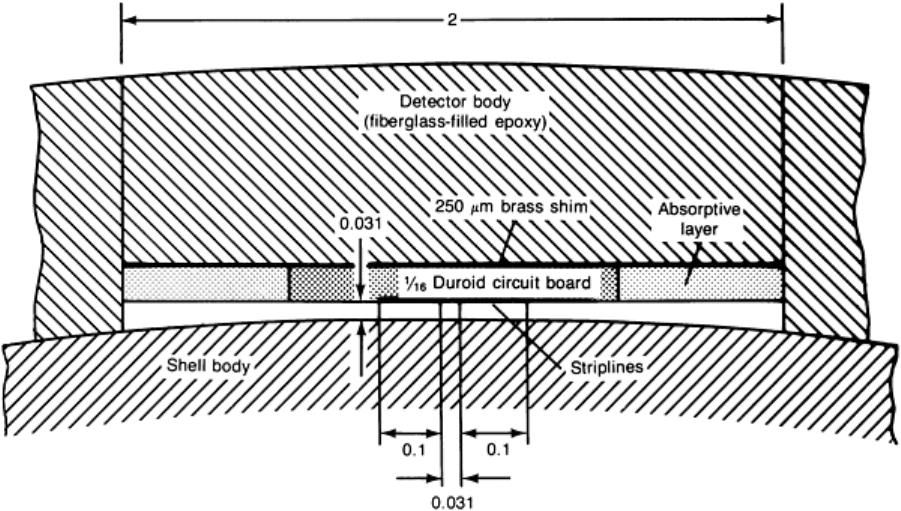
Fig. 34 Cross section of curved stripline crack detector. Dimensions given in inches. Source: Ref 33
The system used with the coupled stripline to detect cracks is shown in Fig. 35. By adjusting the variable attenuator and
phase shifter connected to the output of the probe, it was found possible to achieve 50 to 75 dB of dynamic range (Ref
27). Quadrature detection and subsequent squaring and adding produced a phase-insensitive output. The frequency used
was near 10 GHz. When the system illustrated in Fig. 35 was connected to the crack detector shown in Fig. 34, electric
discharge machining slots as small as 2.54 mm (0.100 in.) long, 0.038 mm (0.0015 in.) wide, and 0.13 mm (0.005 in.)
deep could be detected. It was, however, difficult to maintain high isolation between the even and odd modes (bridge
balance) as the probe scanned the surface. This is usually because of slight lift-off of the detector from the shell. Perhaps
lift-off effects could have been reduced if the in-phase and quadrature-phase signals were used rather than only the
amplitude.
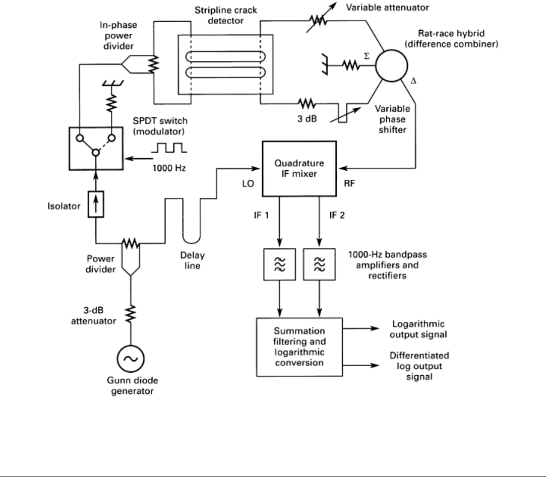
Fig. 35 System for coupled-
stripline surface crack detector. LO, local oscillator; IF, intermediate frequency.
Source: Ref 33
References cited in this section
19.
L. Feinstein and R.J. Hruby, Surface-Crack Detection by Microwave Methods, in
Proceedings of the Sixth
Symposium on Nondestructive Evaluation of Aerospace and Weapons Systems Components and Materials,
Western Periodicals Co., 1967, p 92-106
27.
A.J. Bahr, Microwave Nondestructive Testing Methods, Vol 1, Nondestructive Testing and Tracts,
W.J.
McGonnagle, Ed., Gordon & Breach, 1982, p 49-72
28.
E.E. Collin, Field Theory of Guided Waves, McGraw-Hill, 1960, p 39-40
29.
L. Feinstein and R.J. Hruby, Paper 68-
321, presented at the AIAA/ASME 95th Structures, Structural
Dynamics and Materials Conference, American Insti
tute of Aeronautics and Astronautics/American Society
of Mechanical Engineers, April 1968
30.
R.J. Hruby and L. Feinstein, A Novel Nondestructive, Nonconducting Method of Measuring the Depth of
Thin Slits and Cracks in Metals, Rev. Sci. Instrum., Vol 41, May 1970, p 679-683
31.
A.J. Bahr, Microwave Eddy-Current Techniques for Quantitative Non-Destructive Evaluation, in Eddy-
Current Characterization of Materials and Structures,
STP 722, G. Birnbaum and G. Freed, Ed., American
Society for Testing and Materials, 1981, p 311-331
32.
L.A. Robinson and U.H. Gysel, "Microwave Coupled Stripline Surface Crack Detector," Final Report,
Contract DAAG46-72-C-0019, SRI Project 1490, Stanford Research Institute, Aug 1972
33.
U.H. Gysel and L. Feinstein, "Design and Fabrication of Stripline Microwave Surface-
Crack Detector for
Projectiles," Final Report, Contract DAAG46-73-C-
0257, SRI Project 2821, Stanford Research Institute,
Sept 1974
Microwave Inspection
William L. Rollwitz, Southwest Research Institute
Ferromagnetic Resonance Eddy Current Probes
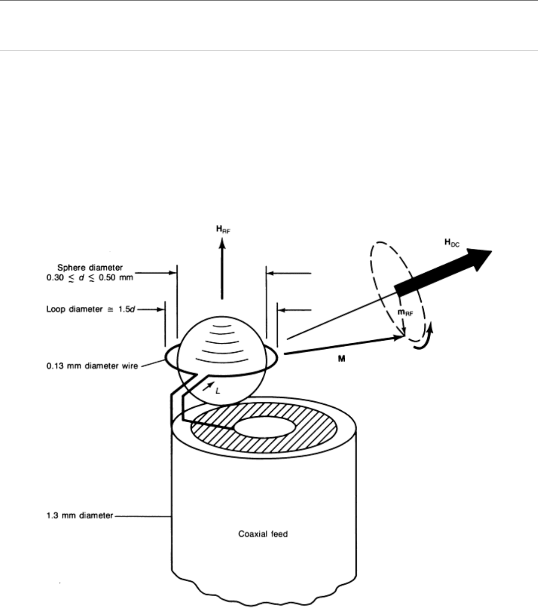
An entirely different eddy current detection head (Ref 34, 35, 36, 37, 38, 39) is illustrated in Fig. 36. Instead of
electromagnetic resonance, this probe makes use of ferromagnetic resonance (FMR) (Ref 40). Ferromagnetic materials
exhibit a natural dispersion in their permeability. Such an effect has been studied in ferrites that typically have two
resonances--one in the range of 3 to 500 MHz and a second at 1200 MHz without an external applied magnetic field (Ref
40). Evidence shows that the higher resonances are due to electron spin (Ref 40). These spin resonances occur naturally
because there is an internal anisotropy magnetic field. This internal magnetic field tends to keep the electron
magnetization vector aligned with a preferred crystal axis (Ref 40). Most of these resonances are very broad.
Fig. 36 Typical dimensions and feed arrangement for a ferromagnetic resonance eddy-current probe. M
,
internal magnetization. Source: Ref 34
Studies of the magnetic resonance of the garnets have given some narrow ferromagnetic resonance lines. Yttrium iron
garnet (YIG) gives a very narrow ferromagnetic resonance line (Ref 40). The line with a polycrystalline YIG shows
internal field values of 33, 14, and 4.0 kA · m
-1
(420, 180, and 50 Oe) (Ref 40). The properties are modified by
substituting for part of the yttrium, chromium, and rare-earth elements such as gadolinium and dysprosium. An
exceptionally narrow line is obtained when the substituted YIG is in the form of polished, single-crystal spheres. The best
result was a width of 41 A · m
-1
(0.52 Oe) (Ref 40). The value of the internal field was 0.175 T (1750 G). The Q-factor for
single crystals in the form of 0.8 mm (0.03 in.) diam spheres, with a line width of 185 A · m
-1
(2.3 Oe), is around 3000 in
the frequency range of 9.5 to 67 GHz. External magnetic fields are required to cover this range of frequencies.
The resonator illustrated in Fig. 36 is a single crystal YIG sphere less than 1 mm (0.04 in.) in diameter. The resonant
frequency of the sphere is determined by the strength and direction of an applied field, H
DC
, shown in Fig. 36. The
internal magnetic field in the YIG comes from the precessing magnetic field of the electrons in the YIG sphere because of
their interaction with the applied magnetic field H
DC
. The radian precession frequency,
0
is determined by:
0
= H
DC
(Eq 12)
where = 2.8 × 10
6
rad/Oe · s. For a resonant frequency range of 500 to 2000 MHz, the value of H
DC
is varied from 14.2
to 56.8 A · m
-1
(178 to 714 Oe). Magnetic field values in this range are readily supplied by small samarium-cobalt and
other types of modern magnets.
Unlike lower-frequency eddy current probes, the coil shown in Fig. 36 is a single turn whose diameter is 1.5 times the
diameter of the YIG sphere or from 0.25 to 0.75 mm (0.01 to 0.03 in.). The diameter of the wire used is 0.13 mm (0.005
in.).
The ferromagnetic resonance is a condition of the ferromagnetic material. When the YIG sphere is so small, boundary
conditions must be taken into account. These lead to an infinite number of resonance modes, called magnetostatic modes,
each with a characteristic distribution of the magnetization within the sphere and a characteristic frequency that depends
on H
DC
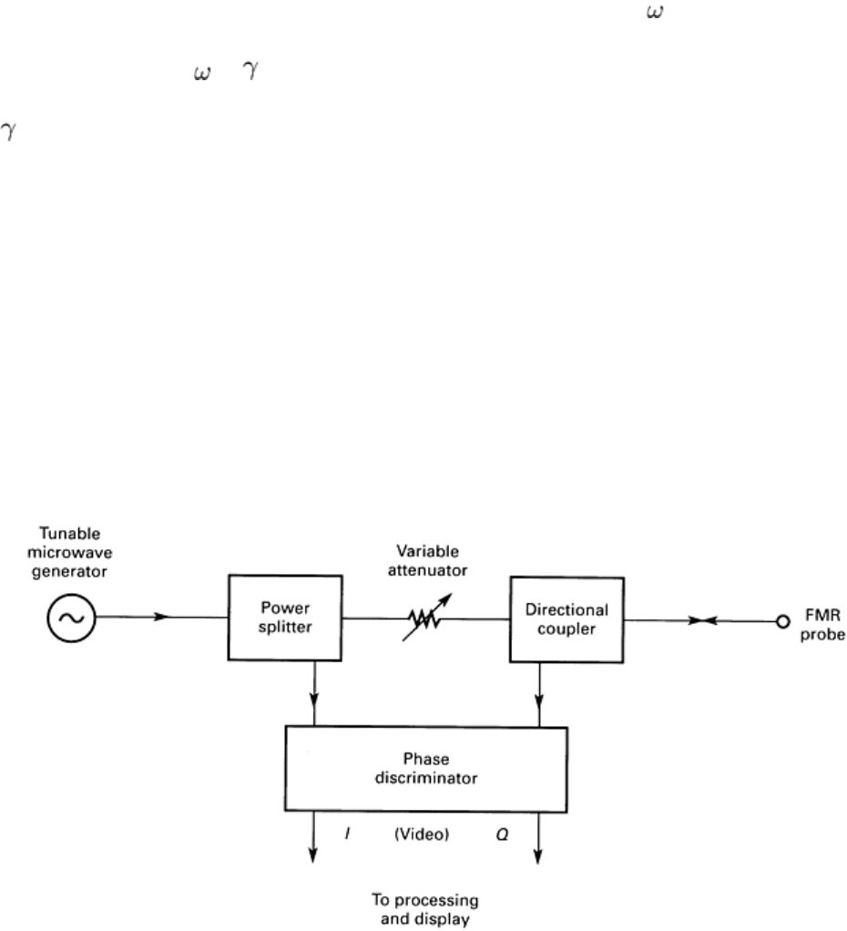
. When the microwave eddy current probe in Fig. 36 is fed as indicated in Fig. 37, the characteristics of a material
placed within the radio-frequency (RF) field (H
RF
) of the coil, as shown in Fig. 36, will cause a change in the losses and
the mode coupling in the YIG. The material close to the probe causes changes in both the amplitude and frequency of the
modes. This in turn will change the energy reflected from the single-turn loop inductor.
Fig. 37 Microwave system for measuring the reflection from an FMR probe. Source: Ref 38
The dominant mode is one in which the magnetization is uniformly distributed throughout the sphere and is precessing
uniformly. The precession frequency is given by Eq 12 and can be represented by an electron dipole moment of strength
(m
RF
V
s
), where V
s
is the volume of the sphere. The dipole moment, because of the cross product between H
DC
and m
RF
, is
precessing about H
DC
at a frequency , according to the right-hand rule, in a plane perpendicular to H
DC
, as shown in Fig.
36. The precession is at the frequency of the drive current, I, applied to the coupling coil. The dipole moment m
RF
obtains
its maximum amplitude when the precession frequency
0
(Eq 14) equals the precession frequency . The time-varying
magnetic fields are created outside of the sphere by this rotating dipole moment. These outside time-varying magnetic
fields interact with a flaw in the material and produce a flaw-detecting signal in the same way that the time-alternating
magnetic fields do from low-frequency (conventional) eddy current probes.
In practice, the YIG sphere is mounted in a depression on a piece of microwave circuit board with a loop etched on the
board. Wire leads connect the end of the loop to a semirigid coaxial transmission line. A small samarium-cobalt magnet in
a brass holder supplies the bias field. The placement of the magnet can be adjusted to change the field orientation and the
resonant frequency. This eddy current probe, because of its small size, gives excellent spatial resolution, discrimination
against edge effects, and accessibility to restricted corners.
The high sensitivity and spatial resolution of the FMR eddy current probe have been experimentally verified (Ref 34, 39).
In one case, the FMR probe was found to be 40 times more sensitive to an open slot than a commercial 100-kHz probe.
The correlation between the flaw signature, detected by the FMR probe, and the width of the opening of a stressed fatigue
crack has also been demonstrated.
Another group of researchers has applied the FMR probe to aluminum, type 316 stainless steel, Armco iron, and XC-38
(Ref 41). They used the YIG and gallium-doped yttrium iron garnet (GaYIG). The main difference between this garnet
and the previous garnet is that the saturation magnetization is fixed at 0.075 T (750 G) for YIG, while that of the GaYIG
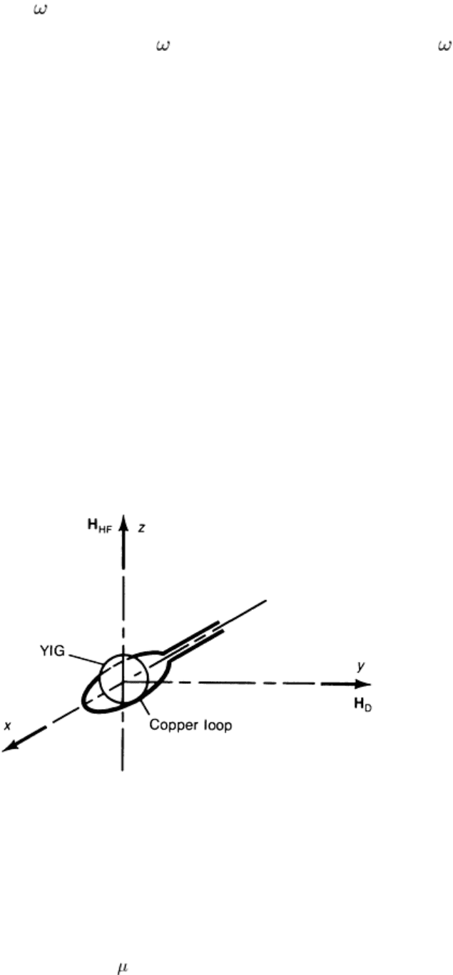
varies with the amount of gallium. The resonator principle that was used is given in Fig. 38. The characterization of the
spectrum line is done by measuring the reflection coefficient of the YIG resonator in Fig. 38. A microwave signal is
applied onto the garnet by means of the copper loop. In the absence of resonance, the wave is reflected. As the resonance
is approached, the incident wave is absorbed by the garnet, and the reflected wave is highly attenuated. The reflection
coefficient is characterized either by a scaler analysis or by a vector analysis.
Fig. 38 Schematic of YIG resonator principle. H
D
, continuous magnetic field; H
HF
, microwave magnetic field.
Source: Ref 41
In air (uncoupled to a sample), the resonant frequency is proportional to the applied bias field H
D
in Fig. 38. The
proportionality constant is 2.8 MHz/Oe. The resonance lines for YIG are located above 3 GHz. For GaYIG, the resonance
frequency can go down to less than 1 GHz.
The garnets used have diameters of 375 or 500 m (0.015 or 0.020 in.). The only garnets used were the YIG, which
required a bias magnetic field between 80 and 160 kA · m
-1
(1000 and 2000 Oe). The microwave loop is made on a
printed circuit. Experience with microwave oscillators has shown that this loop should have a diameter of about 1.5 times
that of the garnet and that the copper width should be 0.1 mm 0.004 in.).

In Ref 41, three different probes (A, B1, B2) were used. These three detection heads are illustrated in Fig. 39. These three
probes are configured for use as follows:
• Probe A is for use with a nonmagnetic metal w
here the magnetic field is parallel to the surface of the
metal and the fringe field of probe A will be in the surface of the nonmagnetic metal
•
Probe B1 is for use with magnetic material where the FMR probe is between the metal and the magnet,
providing the bias field for the YIG, and the RF field is perpendicular to the magnetic metal surface
•
Probe B2 is for use with magnetic material where the FMR probe is between the magnet and the metal
and the RF field from the YIG-coil system is parallel to the metal surface
Head B2 imposes a minimum distance of the order of approximately 1 mm (0.04 in.) between the metal and the garnet
because of the position of the loop. This drawback can be overcome by using a half-loop. In head B1, there are numerous
spurious modes, which are almost as intense as the main mode. However, this head appears to be of particular value in the
separation of the distance effect from the flaw effect.
Fig. 39
Three microwave eddy current detection head configurations that use a YIG coil. (a) A, for nonmagnetic
metal. (b) B1, for magnetic metal, RF field perpendicular to magnetic metal surface. (c) B2, for magneti
c metal,
RF field parallel to magnetic metal surface. Source: Ref 41
The measurement principle is described as the characterization of the resonance line and of its alteration in the presence
of a flaw. The block diagram of the electronics used with the FMR probes is shown in Fig. 40. Figure 40(a) is for the
scalar analysis, and Fig. 40(b) is for the vector analysis. For the scalar analysis, a wobbulator (German for signal
generator, specifically a frequency-modulated RF source) sends a wave through the coupler and through the circulator to
the probe. The signal from the probe goes through the circulator and through a detector to the vertical axis of the
oscilloscope. The signal used to vary the frequency is sent to the horizontal axis of the oscilloscope so that the
oscilloscope presents the resonance of the probe as a function of frequency. An automatic control device makes it possible
to determine the frequency, f, of the peak. The scanning of the metal takes place in a single direction, and the curves f(x)
are plotted. The flaw is characterized as a frequency shift.
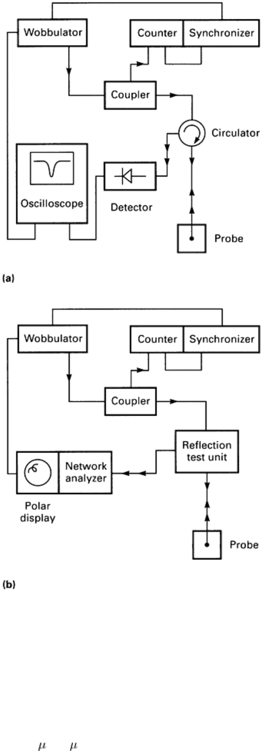
Fig. 40 Schematic diagram for (a) scalar analysis and (b) vector analysis. Source: Ref 41
For the vector analysis, the block diagram shown in Fig. 40(b) is used. The reflected wave is sent to a vector analyzer,
which makes it possible to display the reflection coefficient in the phase plane. The influence of the flaw is characterized
by the displacement of the resonance loop in the phase plane. The synchronizer allows phase locking on the wobbulator to
provide greater frequency stability when required.
Three metals were studied: aluminum, type 316 stainless steel, and Armco iron. The samples are surface ground to an
arithmetic average roughness, R
a
, of 0.1 m (4 in.).
