API Std 617: 2002 Axial and Centrifugal Compressors and Expander-compressors for Petroleum, Chemical and Gas Industry Services
Подождите немного. Документ загружается.


AXIAL AND CENTRIFUGAL COMPRESSORS AND EXPANDER-COMPRESSORS FOR PETROLEUM, CHEMICAL AND GAS INDUSTRY SERVICES 4-27
JOB NO. _____________________ ITEM NO. ____________________
PAGE ________ OF _____ BY _____________________________
DATE __________________ REVISION___________________________
34. A complete list of utility requirements: quantity, filtration and supply pressure of the following:
a. Steam.
b. Water.
c. Electricity.
d. Air.
e. Gas.
f. Lube oil and seal oil (quantity and supply pressure).
g. Heat loads.
h. Power ratings and operating power requirements for auxiliary drivers.
35. A list of machines similar to the proposed machines that have been installed and operating under conditions analogous
to those specified in the inquiry.
36. Any start-up, shutdown or operating restrictions required to protect the integrity of the equipment, including any unac-
ceptable speeds due to natural frequencies.
37. A list of any components that can be construed as being of alternative design, requiring purchaser’s acceptance.
38. A summary of the materials of construction for the compressor, including hardness for materials exposed to H
2
S.
39. The maximum seal gas rates (injection or eduction) and rated or expected inner seal-oil leakage rates, if applicable.
When self-acting dry gas seals are supplied, expected seal gas consumption, minimum seal gas supply flow and pri-
mary vent flow should be given at maximum sealing pressure and at conditions over the operating envelope of the
machine.
40. When interstage coolers are furnished, the vendor shall provide the following:
a. Drawing showing cooling system details.
b. Data for purchasers heat and material balances.
c. Details of provisions for separating and withdrawing condensate.
d. Vendor’s recommendations regarding provision for support and piping expansion.
41. Drawings, details and descriptions of the operations of instrumentation and controls as well as the makes, materials and
type of auxiliary equipment. The vendor shall also include a complete description of the alarm and shutdown facilities
to be provided.
42. The minimum length of straight pipe required for proper flow characteristics at the inlet and at any side inlet connection.
43. Maximum and minimum allowable seal pressure for each compressor.
44. A statement of the manufacturers capability regarding testing (including performance testing) of the compressor and
any other specified items on the train. Details of each optional test specified shall be included.
45. Predicted performance curves shall be provided for compressor and expander including the following:
a. Expander power versus flow.
b. Compressor power versus flow.
c. Compressor head and ratio, four speed lines from 70% – 110% of normal speed lines.
d. Expander v/c versus efficiency.
If a performance test is specified as tested, then curves and data shall be provided.
46. For compressors that have a back-to-back impeller arrangement, the vendor shall furnish a curve showing the expected
loading on the active or inactive side of the thrust bearing versus any combination of differential pressures across the
low pressure and high pressure sections of the casing.
47. The vendor shall supply balance piston leakage based on design clearances and twice design clearances for the rated
conditions.
API STANDARD 617
CHAPTER 4 ANNEX B
VENDOR DRAWING AND
DATA REQUIREMENTS
COPYRIGHT 2002; American Petroleum Institute
Document provided by IHS Licensee=Shell Services International B.V./5924979112,
User=, 10/07/2002 18:49:21 MDT Questions or comments about this message: please
call the Document Policy Management Group at 1-800-451-1584.
-- | ||| | | | |||| || | |||| || | | | | ||| | |---

4-28 API STANDARD 617—CHAPTER 4
JOB NO. _____________________ ITEM NO. ____________________
PAGE ________ OF _____ BY _____________________________
DATE __________________ REVISION___________________________
48. When specified, the vendor shall supply curves of balance piston line differential pressure versus thrust load.
49. The vendor shall provide production and delivery schedules.
50. The vendor shall submit detailed procedures including acceptance criteria for the mechanical running test and all
optional tests, at least 6 weeks prior to the first running test.
51. The vendor shall submit progress reports.
52. All information required for the proper installation of the equipment shall be compiled in a manual that must be issued
no later than the time of final certified drawings.
53. A manual containing all required operating and maintenance instructions shall be supplied not later than 2 weeks after
all specified test shall have been successfully completed.
54. The vendor shall provide a “technical data manual within 30 days of completion” of shop testing including the following:
a. Necessary certification of materials.
b. Purchase specification for all items on the bill of materials.
c. Test data to verify requirements of specifications have been met.
d. Heat treat records.
e. Results of quality test and inspections.
f. Mechanical running test data log.
g. Final assembly maintenance and running clearances.
The vendor is also required to keep this data available for examination by the purchaser, upon request, for at least 5
years.
API STANDARD 617
CHAPTER 4 ANNEX B
VENDOR DRAWING AND
DATA REQUIREMENTS
COPYRIGHT 2002; American Petroleum Institute
Document provided by IHS Licensee=Shell Services International B.V./5924979112,
User=, 10/07/2002 18:49:21 MDT Questions or comments about this message: please
call the Document Policy Management Group at 1-800-451-1584.
-- | ||| | | | |||| || | |||| || | | | | ||| | |---

4-29
ANNEX 4C
EXPANDER-COMPRESSOR NOMENCLATURE
COPYRIGHT 2002; American Petroleum Institute
Document provided by IHS Licensee=Shell Services International B.V./5924979112,
User=, 10/07/2002 18:49:21 MDT Questions or comments about this message: please
call the Document Policy Management Group at 1-800-451-1584.
-- | ||| | | | |||| || | |||| || | | | | ||| | |---
4-30 API S
TANDARD
617—C
HAPTER
4
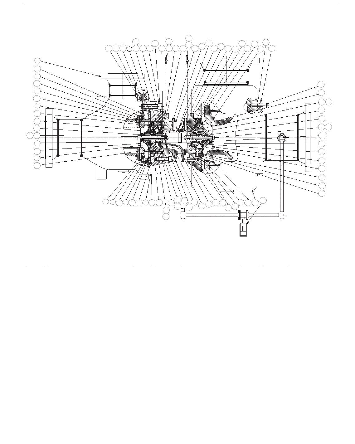
Figure 4.C-1—Typical Expander-compressor Showing Nomenclature of Key Parts
221
981
517
88
434
602
575
447
562
548
159
155
967
127
159
155
126
147
154
168
530
431
533
136
519
183
505
196
181
401
521
432 601
430
186
179
180
163a
518
163
170
138
429
404
185
197
188
411
535
160
520
423
151
515
516
439
448
545
561
137
471
603
550
102
966
68
966
435
89
433
91
93
123
98
107
97
119
118
120
486
466
92
437
90
224
61
93a
90a
Item No. Description Item No. Description Item No. Description
61 Expander case 120 Shaft key (expander) 170 Compressor wheel
68 Labyrinth seal housing 123 Expander wheel back seal 179,180 Retaining screw and retaining washer
88 Nozzle cover 126 Shaft 181 Compressor follower
89 Nozzle segment and cam roller 127 Bearing thrust washer (expander) 183 Shim-compressor follower
90 Nozzle adjusting ring 136 Bearing thrust washer (compressor) 185 Compressor wheel back seal
90a Nozzle clamping ring 137 Bearing-drive 186 Shaft key (compressor)
91 Nozzle fixed ring 138 Bearing-load 188 Compressor case
92 Shim-nozzle fixed ring 147 Bearing housing 196 Compressor inlet spacer
93 Piston ring 151 Bearing housing drain 197 Auto thrust balance assembly
93a Seal ring 154 Tachometer pick-up insert 221 Actuator mount assembly
97 Heat barrier wall insert 155,159 Vibration pick-up and lock nut 224 Nozzle actuator rod
98 Shim-heat barrier wall insert 160 Compressor seal 401 Ð 486 Screw
102 Heat barrier wall 163 Compressor seal insert 505 Ð 575 O-ring
107 Expander wheel 163a Shim-compressor seal insert 601 Ð 603 Washer
118,119 Retaining screw and retaining washer 168 Tachometer pick-up 966 Ð 981 Raco seal
Key
COPYRIGHT 2002; American Petroleum Institute
Document provided by IHS Licensee=Shell Services International B.V./5924979112,
User=, 10/07/2002 18:49:21 MDT Questions or comments about this message: please
call the Document Policy Management Group at 1-800-451-1584.
-- | ||| | | | |||| || | |||| || | | | | ||| | |---

4-31
ANNEX 4D
INSPECTOR’S CHECK LIST
COPYRIGHT 2002; American Petroleum Institute
Document provided by IHS Licensee=Shell Services International B.V./5924979112,
User=, 10/07/2002 18:49:21 MDT Questions or comments about this message: please
call the Document Policy Management Group at 1-800-451-1584.
-- | ||| | | | |||| || | |||| || | | | | ||| | |---
4-32 API STANDARD 617—CHAPTER 4
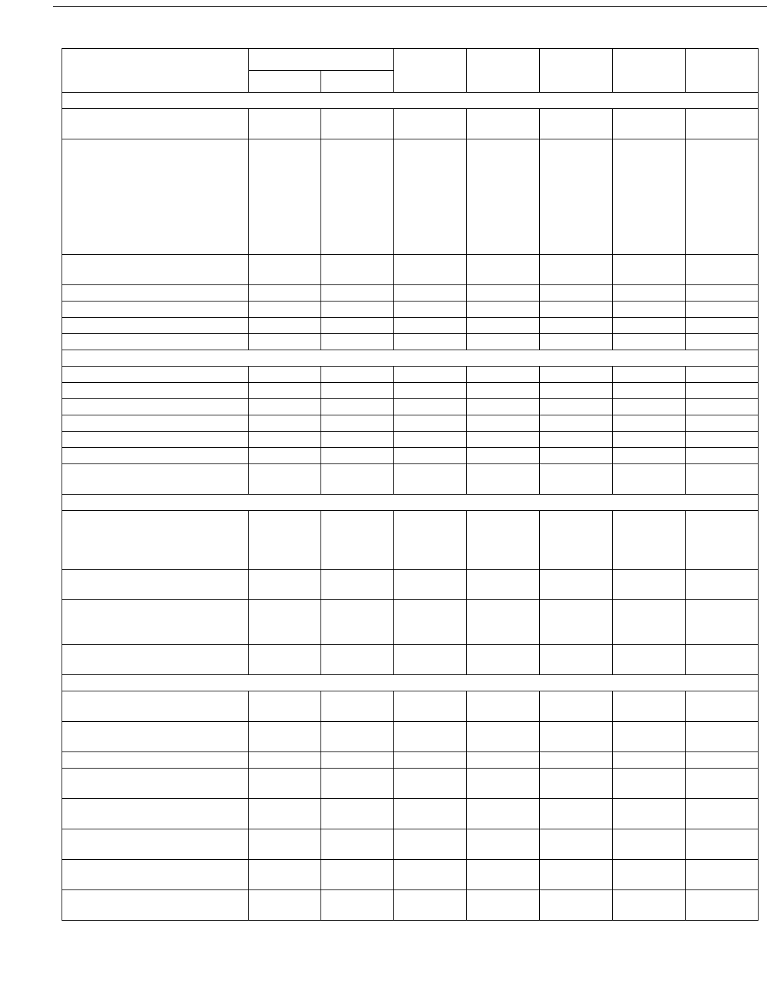
Item
Standard 617
Reviewed Observed Witnessed
Inspected
By StatusPar Ch
GENERAL
Contract Review—Testing and
Inspections Listed in Proposal
2.2.1.4 1
General Test Requirements 4.1.1
4.1.3
4.1.4
4.1.4.1
4.1.6
4.1.7
4.2.1
4.2.1.2
1
1
1
1
1
1
1
1
Cleanliness 4.2.1.3
4.2.1.4
1
1
Hardness 4.2.1.5 1
Case Support Mounting Surfaces 2.3.3 4
Nameplate 2.11.2 4
Rotation Arrows 2.11.1 4
MATERIAL INSPECTIONS
Material Inspections 4.2.2.1 1
Castings 2.2.2.1 1
Low Temperature Impact 2.2.1.15.5 1
Forgings 2.2.3.2 1
Weldings 2.2.4.1 1
Pressure-containing Casings 2.3.1 1
Material Inspection of Pressure-
containing Parts
2.3.1.12 1
ROTATING ELEMENT
Impellers 2.5.10.4
2.5.10.5
2.5.10.6
4.3.3.1
1
1
1
1
Overspeed 2.5.10.7
4.3.3.1
1
1
Balance 2.6.8
2.6.8.8
Annex B
1
1
Run-out 2.6.8.9
2.6.8.10
1
1
ACCESSORIES
Shaft End Seals 4.3.5
Annex D
1
Lubrication and Sealing Systems 2.10.3
API Std 614
1
Drivers 3.1 1
Steam Turbine 3.1.4
API Std 612
1
Motor 3.1.5
API Std 541
1
Gas Turbine 3.1.7
API Std 616
1
Separate Gear Units 3.1.8
API Std 613
1
Coupling and Guard 3.2
API Std 671
1
COPYRIGHT 2002; American Petroleum Institute
Document provided by IHS Licensee=Shell Services International B.V./5924979112,
User=, 10/07/2002 18:49:21 MDT Questions or comments about this message: please
call the Document Policy Management Group at 1-800-451-1584.
-- | ||| | | | |||| || | |||| || | | | | ||| | |---
AXIAL AND CENTRIFUGAL COMPRESSORS AND EXPANDER-COMPRESSORS FOR PETROLEUM, CHEMICAL AND GAS INDUSTRY SERVICES 4-33
Instrumentation 3.4.3
3.4.4
API Std 614
API Std 670
1
1
Alarms and Shutdowns 3.4.5
API Std 614
1
Electrical Systems 3.4.6
API Std 614
2.1.14
1
1
Piping 3.5.1
API Std 614
1
Special Tools 3.6.1
3.6.2
1
1
TESTING
Test Data Log 4.3.1.2 4
Wheel Skaker Test to Verify
Natural Frequency
4.3.2 4
HYDROSTATIC TEST
Hydrostatic Test 4.3.2.1
4.3.2.2
4.3.2.3
1
1
1
OVERSPEED TEST
Impeller Overspeed Test 4.3.3.1 1
MECHANICAL RUNNING TEST
Unbalance Response Verification 2.6.3.1 1
Vibration Record 2.6.3.1.1
4.3.6.1.1
4.3.6.1.2
4.3.6.1.3
1
1
1
1
Contract Shaft Seals Used in Test 4.3.6.1.4 1
Oil Flow Rates P. & T. 4.3.3.1.2 4
Oil System Clean 4.3.3.1.3 4
Warning Protective Control
Devices Checked
4.3.3.1.6 4
Magnetic Bearing Check 4.3.3.1.4 4
Connections Check for Leaks 4.3.3.1.5 4
Vibration Levels 4.3.3.1.11 4
Test Speeds Performed 4.3.3.2.1 4
Test Run at Trip Speed 4.3.3.2.3 4
4-hour Test Run 4.3.3.2.2 4
Seal Flow Data 4.3.3.1.2 4
Contract Shaft Seals Used in Test 4.3.3.1.1 4
Test Instrumentation Check 4.3.3.1.7 4
Lube and Seal Oil Flows Varied 4.3.6.1.5 1
Vibration Levels 4.3.3.3.1
4.3.3.3.2
4
4
Lateral Critical Speed Verified 4.3.3.3.3 4
Unbalance Response Analysis
Verified
4.3.3.3.4 4
Spare Center Section Test 4.3.3.3.6 4
Bearing Inspected After Test 4.3.3.4.1 4
Seals Inspected After Test 4.3.3.4.2 4
Assembled Compressor Gas Leak 4.3.4.1
4.3.4.2
4
4
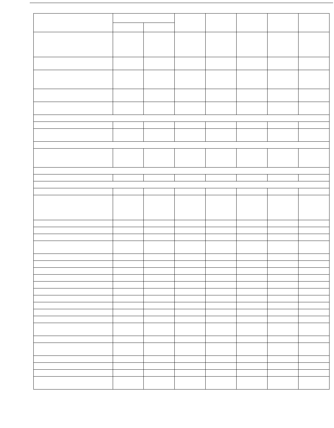
Item
Standard 617
Reviewed Observed Witnessed
Inspected
By StatusPar Ch
COPYRIGHT 2002; American Petroleum Institute
Document provided by IHS Licensee=Shell Services International B.V./5924979112,
User=, 10/07/2002 18:49:21 MDT Questions or comments about this message: please
call the Document Policy Management Group at 1-800-451-1584.
-- | ||| | | | |||| || | |||| || | | | | ||| | |---
4-34 API STANDARD 617—CHAPTER 4
OPTIONAL TESTING 4.3.5 4
Performance Test 4.3.5.1
4.3.5.1.1
4.3.5.1.2
4.3.5.1.3
4.3.5.1.4
4
4
4
4
4
Post-test Inspection 4.3.5.2 4
Helium Test 4.3.8.2 1
Sound-level Test 4.3.8.3 1
Auxiliary Equipment Test 4.3.8.4 1
Post-test Inspection of
Compressor Internal
4.3.8.5 1
Full-pressure/Full-load/
Full-speed Test
4.3.8.6 1
Post-test Inspection of Hydraulic
Coupling Fit
4.3.8.7 1
Spare Parts Test 4.3.8.8
4.3.5.3
1
4
PREPARATION FOR SHIPMENT
Equipment Prepared 4.4.1
4.4.2
1
1
Paint 4.4.3.1 1
Exterior Machined
Surfaces Coated
4.4.3.2 1
Bearing Housings, Oil Systems,
Auxiliary Equipment and Piping
Preserved
4.4.3.4 1
Openings Covered and Protected 4.4.3.5
4.4.3.6
4.4.3.7
1
1
1
Lifting Points Identified 4.4.3.8 1
Equipment Identified, Tagged,
Packing List
4.4.3.9 1
Spare Rotor Prepared for Storage 4.4.3.10 1
Exposed Shafts, etc. Prepared for
Shipment
4.4.3.12 1
Auxiliary Piping Connections
Tagged or Stamped
4.4.4
4.4.5
1
1
Installation, Instructions Shipped
with Equipment
4.4.6 1
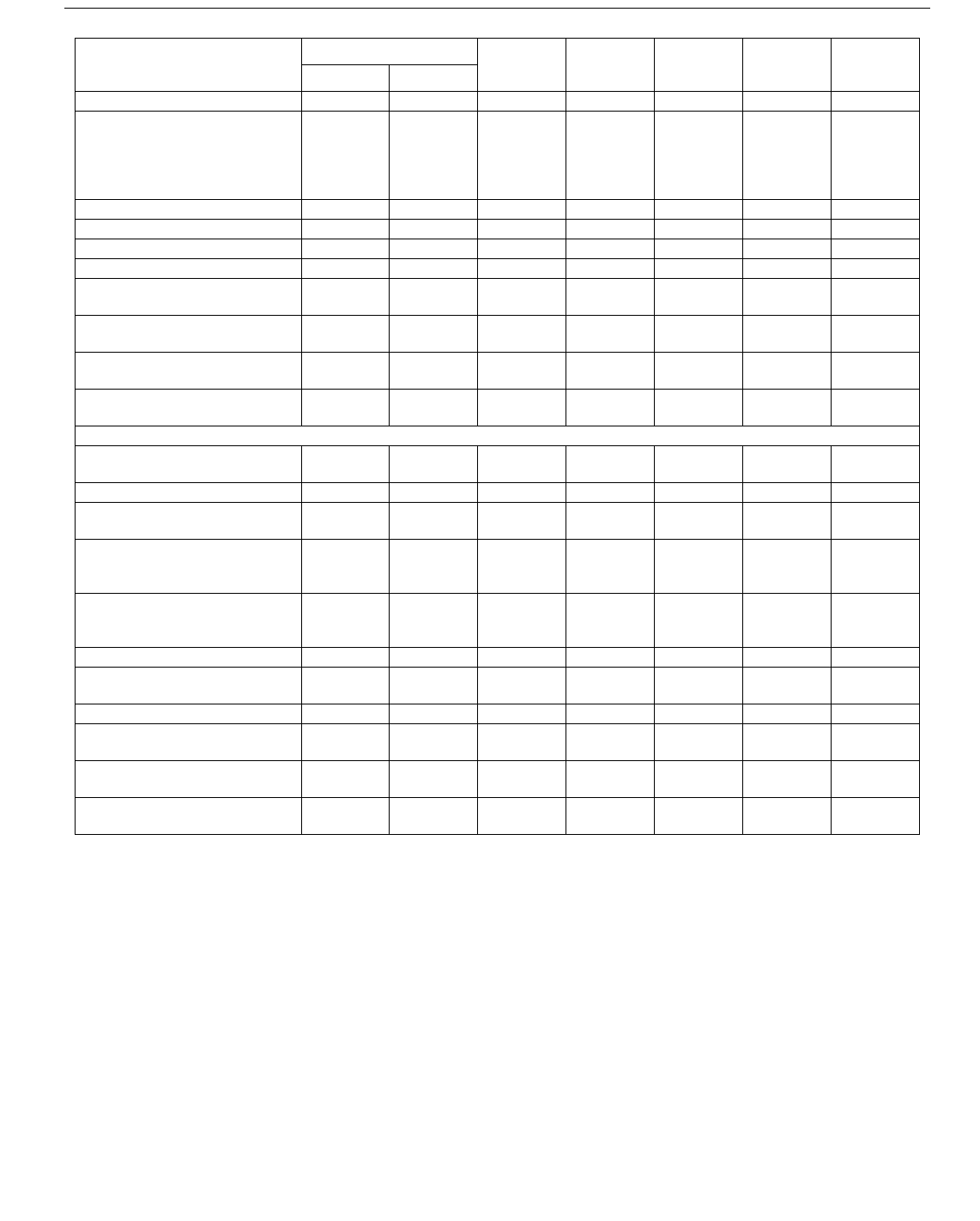
Item
Standard 617
Reviewed Observed Witnessed
Inspected
By StatusPar Ch
COPYRIGHT 2002; American Petroleum Institute
Document provided by IHS Licensee=Shell Services International B.V./5924979112,
User=, 10/07/2002 18:49:21 MDT Questions or comments about this message: please
call the Document Policy Management Group at 1-800-451-1584.
-- | ||| | | | |||| || | |||| || | | | | ||| | |---

4-35
ANNEX 4E
FORCES AND MOMENTS
COPYRIGHT 2002; American Petroleum Institute
Document provided by IHS Licensee=Shell Services International B.V./5924979112,
User=, 10/07/2002 18:49:21 MDT Questions or comments about this message: please
call the Document Policy Management Group at 1-800-451-1584.
-- | ||| | | | |||| || | |||| || | | | | ||| | |---
4-36 API STANDARD 617—CHAPTER 4
E.1 General
E.1.1 The April 1988, November 1979, and October 1973
issues of this standard referred nozzle forces and moments
calculations to appropriate NEMA documents, with the stipu-
lation that the constants in the equations be multiplied by
1.85. Experience has shown that there has not been a uniform
interpretation of “1.85 times NEMA.” Therefore, the equa-
tions have been adapted to expander-compressors by identify-
ing all the constants and clarifying that the equivalent of the
exhaust nozzle in the NEMA calculation is the largest
expander or compressor nozzle. This is usually, but not neces-
sarily, the outlet nozzle.
E.1.2 For expanders designed for driving separate gear-
boxes or generators, which require high tolerance of align-
ment between the expanders and the gearboxes/generators,
the vendor shall identify the maximum allowable forces and
moments.
Note: 0.2 times NEMA is often required for this type of the
arrangement.
E.2 Equations
The design of each expander-compressor body must allow
for limited piping loads on the various casing nozzles. For
maximum system reliability, nozzle loads imposed by piping
should be as low as possible regardless of the expander-com-
pressor load-carrying capability. For single stage expander-
compressors, the forces and moments acting on expander or
compressor due to the inlet and discharge connections should
be limited by the following:
a. The total resultant force and total resultant moment
imposed on the compressor at any connection should not
exceed the values shown in Equations 4.E-1a or 4.E-1b.
In SI units:
F
r
+ 1.09 M
r
≤ 54.1D
e
(4.E-1a)
In U.S. Customary units:
3F
r
+ M
r
≤ 927 D
e
(4.E-1b)
where
F
r
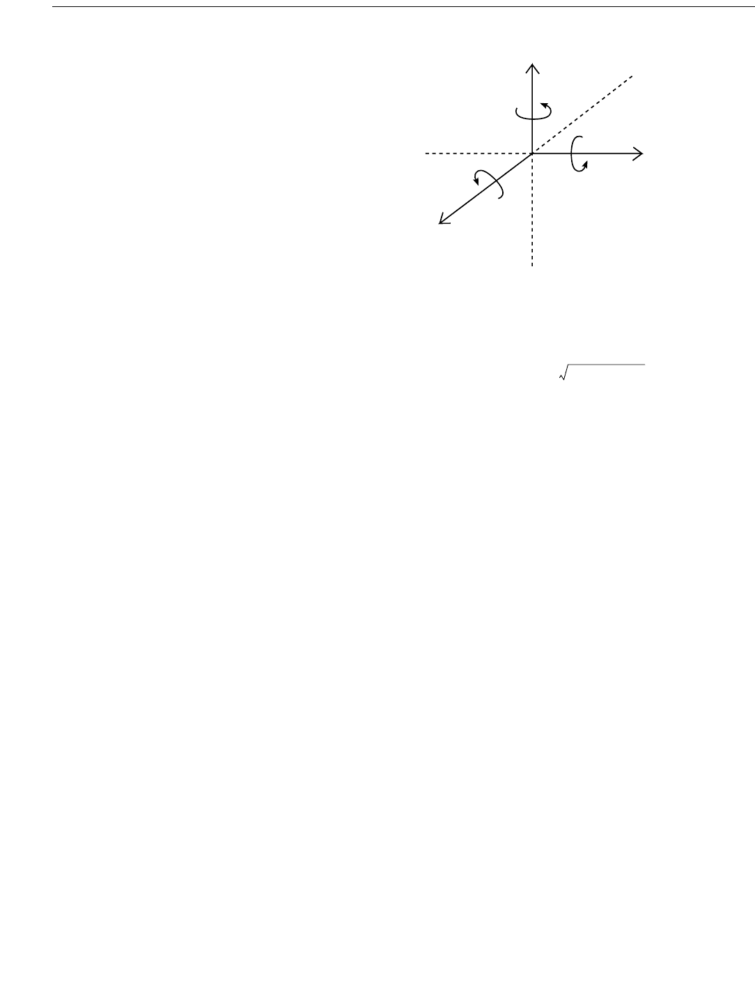
= resultant force, in Newtons (lb.) (see Figure
4.E-1),
M
r
= resultant moment, in Newton-meters (ft-lb.)
from Figure 4.E-1.
For sizes up to 200 mm (8 in.) in diameter:
(4.E-2)
D
e
= Nominal pipe diameter of the connection, in
mm (in.).
For sizes greater than 200 mm (8 in.), use a value of:
In SI units:
(mm) (4.E-3a)
In U.S. Customary units:
(in.) (4.E-3b)
where
D
c
= equivalent pipe diameter of the connection, in
mm (in.),
D
nom
= nominal pipe diameter, in mm (in.).
b. The combined resultants of the forces and moments of the
inlet, sidestream, and discharge connections resolved at the
centerlines of the largest connection should not exceed the
following:
1. The resultants shall not exceed:
In SI units:
F
c
+ 1.64M
c
≤ 40.4 D
c
(4.E-4a)
Figure 4.E-1—Combined Resultants of the Forces and
Moments of Corrections
M
y
F
y
M
z
F
z
Z
+
F
x
M
x
I
VERTICAL
PARALLEL TO
COMPRESSOR SHAFT
M
t
M
x
M
y
M
z
++=()
D
e
400 D
nom
+
3
--------------------------=
D
e
16 D
nom
+
3
-----------------------=
COPYRIGHT 2002; American Petroleum Institute
Document provided by IHS Licensee=Shell Services International B.V./5924979112,
User=, 10/07/2002 18:49:21 MDT Questions or comments about this message: please
call the Document Policy Management Group at 1-800-451-1584.
-- | ||| | | | |||| || | |||| || | | | | ||| | |---
