API RP 2A-WSD-2007 Recommended Practice for Planning, Designing and Constructing Fixed Offshore Platforms-Working Stress Design
Подождите немного. Документ загружается.

RECOMMENDED PRACTICE FOR PLANNING, DESIGNING AND CONSTRUCTING FIXED OFFSHORE PLATFORMS—WORKING STRESS DESIGN 249
COMMENTARY ON MATERIAL, SECTION 8
C8.2 STRUCTURAL STEEL PIPE
Tubulars used as structural components are often subjected
to substantial axial and hoop stresses. Test data on tubulars
fabricated with circumferential and longitudinal seams have
provided insight into the effects of geometric imperfections
and residual stresses introduced during fabrication and
allowed development of empirical formulations to define
elastic and critical buckling stresses as well as the interaction
relationships between the axial and hoop stresses. Unless suf-
ficient test data are obtained on spiral welded tubulars to eval-
uate applicability of API recommended empirical
formulations, spiral welded tubulars cannot be recommended
for structural use.
COMMENTARY ON WELDING,
SECTION 10.2.2
C10.2.2 Charpy impact testing is a method for qualitative
assessment of material toughness. Although lacking the tech-
nical precision of crack tip opening displacement (CTOD)
testing, the method has been and continues to be a reasonable
measure of fracture safety, when employed with a definitive
program of nondestructive examination to eliminate weld
area imperfections. The recommendations contained herein
are based on practices which have generally provided satis-
factory fracture experience in structures located in moderate
temperature environments (e.g., 40°F sea water and 14°F air
exposure). For environments which are either more or less
hostile, impact testing temperatures should be reconsidered,
based on local temperature exposures.
For critical welded connections, the technically more exact
CTOD test is appropriate. CTOD tests are run at realistic tem-
peratures and strain rates, representing those of the engineer-
ing application, using specimens having the full prototype
thickness. This yields quantitative information useful for
engineering fracture mechanics analysis and defect assess-
ment, in which the required CTOD is related to anticipated
stress levels (including residual stress) and flaw sizes.
Achieving the higher levels of toughness may require some
difficult trade-offs against other desirable attributes of the
welding process - for example, the deep penetrations and rel-
ative freedom from trapped slag of uphill passes.
Since AWS welding procedure requirements are concerned
primarily with tensile strength and soundness (with minor
emphasis on fracture toughness) it is appropriate to consider
additional essential variables which have an influence on
fracture toughness—i.e., specific brand wire/flux combina-
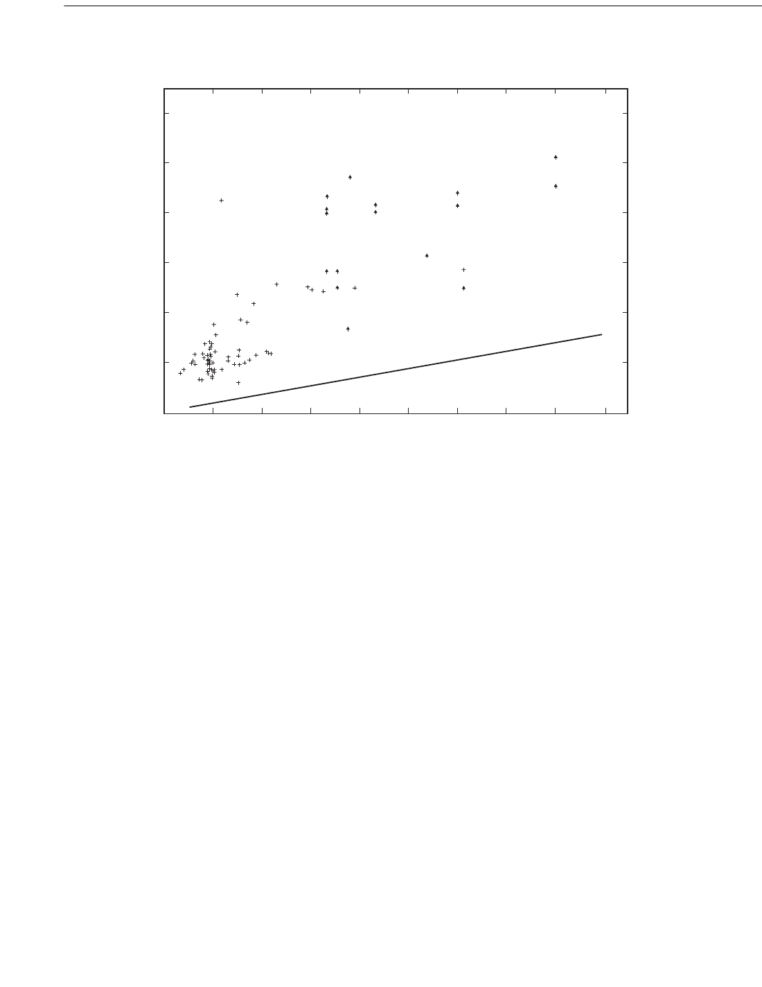
Figure C7.4.4a-2—Measured Bond Strength vs. Cube Compressive Strength
Times the Height-to-Spacing Ratio
0.00
0.30
0.60
0.90
1.20
1.50
1.80
0.00
2.07
4.14
6.21
8.28
10.35
12.42
0.00
0.10
0.20 0.30 0.40 0.50 0.60 0.70 0.80 0.90
0.00 0.69 1.38 2.07 2.76 3.45 4.14 4.83 5.52 6.21
FCU (H/S) in ksi
FCU (H/S) in MPA
FBU in ksi
FBU in MPA
Measured bond strength vs. cube compressive
strength times the height to spacing ratio for
85 tests of grouted tubular joints
with shear connectors
Reference 1 and 2
Reference 8
FBA = 20 + 0.5 FCU (M/S), psi
Copyright American Petroleum Institute
Provided by IHS under license with API
Licensee=Indonesia location/5940240008
Not for Resale, 10/22/2008 00:07:12 MDT
--`,,```,,,`,,,,,,,,,,,,,,`,``,`-`-`,,`,,`,`,,`---
250 API RECOMMENDED PRACTICE 2A-WSD
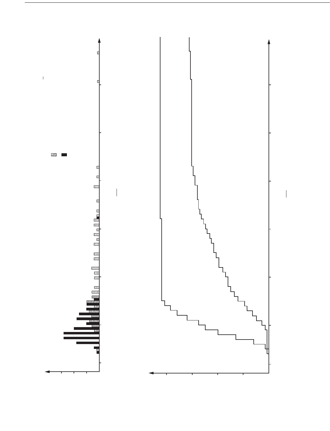
With shear connectors
Without shear connectors
20
40
60
80
1.0
5.0 10.0 15.0 20.0 25.0 30.0
Accumulative Number of Tests
Safety Factor:
Fbu
Fba
15
10
5
1.0
5.0 10.0 15.0 20.0 25.0 30.0
Number of Tests
Straight line equat ion: Fba = 20 + 0.5 Fcu psi
Without shear connectors, 62 tests
Wi t h shear co n n ect ors, 85 t est s
h
s
Saf et y Fact o r :
Fb u
Fb a
Figure C7.4.4a-4—Cumulative Histogram of Safety Factors
Figure C7.4.4a-3—Number of Tests for Safety Factors
Copyright American Petroleum Institute
Provided by IHS under license with API
Licensee=Indonesia location/5940240008
Not for Resale, 10/22/2008 00:07:12 MDT
--`,,```,,,`,,,,,,,,,,,,,,`,``,`-`-`,,`,,`,`,,`---

RECOMMENDED PRACTICE FOR PLANNING, DESIGNING AND CONSTRUCTING FIXED OFFSHORE PLATFORMS—WORKING STRESS DESIGN 251
tions, and the restriction of AWS consumables to the limits
actually tested for AWS classification. Note that, for Class A
steels, specified energy levels higher than the AWS classifica-
tions will require that all welding procedures be qualified by
test, rather than having prequalified status.
Heat affected zone. In addition to weld metal toughness,
consideration should be given to controlling the properties of
the heat affected zone (HAZ). Although the heat cycle of
welding sometimes improves base metals of low toughness,
this region will more often have degraded properties. A num-
ber of early failures in welded tubular joints involved frac-
tures which either initiated in or propagated through the
HAZ, often before significant fatigue loading.
AWS D1.1-2002 Appendix III gives requirements for sam-
pling both weld metal and HAZ, with Charpy energy and
temperature to be specified in contract documents. The fol-
lowing average HAZ values have been found by experience
to be reasonably attainable, where single specimen energy
values (one of three) 5 ft-lbs (7J) lower are allowed without
requiring retest:
As criticality of the component’s performance increases,
lower testing temperatures (implying more restrictive weld-
ing procedures) would provide HAZ’s which more closely
match the performance of the adjoining weld metal and par-
ent material, rather than being a potential weak link in the
system. The owner may also wish to consider more extensive
sampling of the HAZ than the single set of Charpy tests
required by AWS, e.g., sampling at 0.4-mm, 2-mm, and 5-
mm from the fusion line. More extensive sampling increases
the likelihood of finding local brittle zones with low tough-
ness values.
Since HAZ toughness is as much dependent on the steel as
on the welding parameters, a preferable alternative for
addressing this issue is through weldability prequalification
of the steel. API RP 2Z spells out such a prequalification pro-
cedure, using CTOD as well as Charpy testing. This prequali-
fication testing is presently being applied as a supplementary
requirement for high-performance steels such as API Specs
2W and 2Y, and is accepted as a requirement by a few pro-
ducers.
Caution: AWS permits testing one 50-ksi steel to qualify
all other grades of 50-ksi and below. Consequently, selection
of API-2H-50-Z (very low sulfur, 200 ft-lb upper shelf
Charpies) for qualification test plates will virtually assure sat-
isfying a HAZ impact requirement of 25 ft-lbs, even when
welded with high heat inputs and high interpass temperatures.
There is no reasonable way to extrapolate this test to ordinary
A572 grade 50 with the expectation of either similar HAZ
impact energies or similar 8:1 degradation. Thus, separate
Charpy testing of each API steel class is appropriate, if HAZ
toughness is being addressed via WPQ (weld procedure qual-
ification) testing.
COMMENTARY ON MINIMUM
STRUCTURES, SECTION 16
C16.2 Design Loads and Analysis
Analysis and design procedures contained in this recom-
mended practice are usually appropriate for minimum struc-
tures. However, these procedures have evolved from
historical experience primarily involving conventional four
and eight leg, welded, template type structures. Minimum
structures may exhibit structural behavior different from con-
ventional structures. Special consideration should be given
the following:
1. Minimum structures tend to be less stiff than conventional
structures, hence dynamic effects and fatigue are of more
concern even in shallow water depths.
2. Minimum structures typically are less redundant than con-
ventional structures. For example, such structures are more
sensitive to design oversights, fabrication and welding devia-
tions, in-service damage, fatigue and deterioration due to
corrosion.
3. Reserve strength is important in any structure exposed to
unforeseen loading conditions such as accidental loading
from vessels or greater than predicted environmental loads.
Reserve strength is usually lower in less redundant structures
unless the designer makes provisions otherwise. These provi-
sions may include reductions in acceptable interaction ratios
used for member design as well as designing joints for the
full yield strength of the connecting members.
4. Many minimum structures utilize connection and compo-
nent types other than conventional welded tubular joints.
Offshore experience with these complex joints is limited;
therefore connection performance and reliability is of concern
especially when utilized in a low redundancy structure. Con-
sideration of joint flexibility, which is not commonly
02
Table C10.2.2—Average HAZ Values
Steel
Group
Steel
Class
Impact Test
Temperature
Heat Affected Zone
Ft-Lbs (Joules)
IC50°F (10°C) for information only
IB40°F (4°C) 15 20
IA14°F (–10°C) 15 20
II C 50°F (10°C) for information only
II B 40°F (4°C) 15 20
II A 14°F (–10°C) 25 34
III A 14°F (–10°C) 30 40
Copyright American Petroleum Institute
Provided by IHS under license with API
Licensee=Indonesia location/5940240008
Not for Resale, 10/22/2008 00:07:12 MDT
No reproduction or networking permitted without license from IHS

252 API RECOMMENDED PRACTICE 2A-WSD
accommodated during global structural analysis, may
become important.
Evaluation of reserve strength and redundancy should be
balanced by consequences of failure. The consequences of
failure of a minimum structure are usually lower since most
are designed for:
1. Minimum topside facilities.
2. Unmanned operations.
3. One to six wells.
4. Drilling and work-over activity to be performed by a
mobile drilling rig.
It is entirely appropriate for such a structure to have lower
reserve strength and less redundancy than a conventional
structure. However, under no circumstances should a quarters
or oil storage platform be classified as a low consequence of
failure structure.
Experience with minimum structures indicates possible
hindrance of human performance, due to structural move-
ment, from operating environmental conditions. The owner
may choose to accept possible reduced operating and produc-
tion efficiency. However the owner may also choose to per-
form a dynamic response analysis using owner selected
environmental loads. The results can be compared to a per-
sonnel comfort graph (which depicts period vs. peak acceler-
ation or similar criteria (1.2)).
C16.3.3d Grouted Connections
The recommendation that all axial load transfer be accom-
plished using only shear keys is made to insure the integrity
of pile-pile sleeve connection. The significant movement
inherent in these light weight structures could materially
degrade the grout bond strength in such conditions.
C16.4.2 Caissons
There is a history of successful use of Class C material in
caissons at service temperatures above freezing. However,
most of this history was generated when F
b
= 0.66 F
y
.
(F
b
= 0.75 F
y
starting with API RP 2A, 17th Edition, April 1,
1987).
Therefore, since caissons are primarily subjected to envi-
ronmentally induced bending, the use of an interaction ratio
allowable of 0.85 will closely approximate the use of F
b
=
0.66 F
y
rather than F
b
= 0.76 F
y
.
References
(1) Richart, Jr., F. E., Hall, Jr., J. R. and Woods, R. D.,
“Vibrations of Soils and Foundations,” Prentice-Hall, Inc.
(2) Reese, R. C., and Picardi, E. A., “Special Problems of
Tall Buildings,” International Association for Bridge and
Structural Engineering, Eighth Congress, Sept., 1968.
C17 COMMENTARY ON SECTION 17—
ASSESSMENT OF EXISTING
PLATFORMS
C17.1 GENERAL
Background. In engineering practice, it is widely recog-
nized that although an existing structure does not meet
present-day design standards, the structure may still be ade-
quate or serviceable. Examples of this not only include fixed
offshore platforms, but also buildings, bridges, dams, and
onshore processing plants. The application of reduced criteria
for assessing existing facilities is also recognized in risk man-
agement literature, justified on both cost-benefit and societal
grounds.
Structural Integrity Management. Assessment forms
one part of the life-cycle Structural Integrity Management
(SIM) process for existing structures. The SIM process is
continuous and is used as a means of determining whether an
existing structure is capable of fulfilling its required function,
based upon a fitness-for-purpose philosophy. The essence of
the approach is based upon a realistic appraisal of the struc-
ture in conjunction with an effective topside and underwater
survey and planned maintenance program. Assessment
involves gathering all the known facts about a structure's con-
figuration, condition and loading, analyzing the structure
using realistic techniques, comparing analysis results with the
evidence from survey of the structure, and correlating and
refining both analysis and survey. This information is then
used to make an engineering judgment on the structure’s
integrity and fitness-for-purpose. Mitigation is required when
the risk levels exceed the fitness-for-purpose criteria. As the
definition implies, assessment is concerned with existing real
situations as opposed to the process of new design, which is
concerned with future, yet to be built facilities. Platform own-
ers that follow the SIM process should be able to operate their
facilities for an extended period of time.
Change-of-Use. In situations where a platform Change-of-
Use occurs, some of the approaches described in Section 17
are not appropriate since the original purpose of the platform
has changed. Examples of platform Change-of-Use include
the addition of a significant pipeline crossing to an existing
platform, the use of an existing platform as a tie-back for a
deepwater facility, and the conversion of an existing platform
into a receiving terminal for LNG or other non exploration
and production activity. In these cases, the use of the offshore
structure has changed since the platform now has a different
function, expected life and consequence of failure. For exam-
ple, fatigue may have to be re-evaluated in detail since the
structure now has a significantly longer term use under per-
05
05
Copyright American Petroleum Institute
Provided by IHS under license with API
Licensee=Indonesia location/5940240008
Not for Resale, 10/22/2008 00:07:12 MDT
No reproduction or networking permitted without license from IHS
RECOMMENDED PRACTICE FOR PLANNING, DESIGNING AND CONSTRUCTING FIXED OFFSHORE PLATFORMS—WORKING STRESS DESIGN 253
haps different loading conditions compared to its original
design. A more rigorous above and below water survey may
also be warranted. Section 15.2.3, Inspection of Reused Plat-
forms, provides some guidance for more rigorous surveys,
adjusted appropriately for an in-place platform. However,
several of the Section 17 approaches may still be applicable,
for example, the use of design and ultimate strength checks,
where local component failure is acceptable, provided that
the reserve against overall system failure and deformations
remains acceptable. The platform owner should develop a
systematic approach for the evaluation and where required,
modification, for these types of structures that combines the
merits of new design contained in Section 2, as well as the
assessment approach contained in Section 17. In such cases
the platform would not have to meet the minimum deck
height requirements of Section 2.3.4.d3, Elevation of Under-
side of Deck, although wave-in-deck loading would have to
be accounted for explicitly.
Reduced Criteria
. Although the use of reduced criteria for
assessing existing structures is well recognized, the use of the
criteria in Section 17 results in existing platforms that may not
withstand the same level of metocean loading as new plat-
forms designed to the corresponding exposure levels in Sec-
tion 2. Table C17.1-1 provides a comparison of Section 17
assessment wave height criteria to Section 2 new design wave
height criteria for a 400 ft water depth platform. Also shown is
the approximate annual return period for each wave height,
considering the Gulf of Mexico full population of hurricanes
(Krieger, et. al., 1994 [4], Petrauskas, et. al., 1994 [6]). Note
that wave heights and return periods for other water depths
will differ. A platform owner should take into account the
higher risk of platform failure in extreme hurricanes, in com-
parison to new design, when using the reduced Section 17 cri-
teria.
Application of Section 17 Outside of the U.S. The
assessment process is generic and applicable for existing plat-
forms in all offshore areas in terms of the overall approach
and use of a stepwise procedure for demonstrating fitness-for-
purpose. The exception is the use of reduced criteria, which
was developed specifically for the U.S. areas indicated in
Section 17. The use of reduced criteria for assessment may
not be applicable in other offshore areas, unless special stud-
ies indicate otherwise. These studies should be in-depth and
consider platform design, fabrication, installation and opera-
tion specific for the region as well as the local environmental
conditions. The studies should be similar to those that support
the application of the reduced criteria for U.S. areas, and as
described in the Section 17 references.
Section 17 References. The references noted for Section
17 did not follow the review and balloting procedures neces-
sary to be labeled API documents and in some cases reflect
the opinions of only the authors.
C17.2 PLATFORM ASSESSMENT INITIATORS
C17.2.4 Inadequate Deck Height
Inadequate cellar deck height is considered an initiator
because most historical platform failures in the U.S. Gulf of
Mexico have been attributed to waves impacting the platform
cellar deck, resulting in a large step-wise increase in loading.
In a number of these cases this conclusion is based on hurri-
cane wave and storm surge hindcast results, which indicate
conditions at the platform location that include estimated
wave crest elevations higher than the underside (bottom ele-
vation) of the platform's cellar deck main beams.
A cellar deck is defined as a deck that has substantial deck
structure and/or equipment that the wave loading will
increase dramatically in a step-wise manner once the wave
reaches the deck. Figure C17.6.2-1a provides a schematic
representation of typical deck configurations for Gulf of
Mexico platforms, and should be used as guidance in defin-
05
05
05
Table C17.1-1—Comparison of Section 2 L-1 Wave Criteria and Section 17 Wave Criteria for 400 ft. Water
Depth, Gulf of Mexico
API RP 2A Criteria
Wave Height Criteria
Gulf of Mexico, 400 ft. Water Depth*
Design Level Assessment Height /
Annual Return Period
Ultimate Strength Assessment
Height / Annual Return Period
New Design (Section 2, L-1) 70 ft / 100 yr. Not Applicable
A-1 High (Section 17) 57 ft / 30 yr. 74 ft. / 200 yr.
A-2 Medium (Section 17) 48 ft / 15 yr. 62 ft. / 45 yr.
A-3 Low (Section 17) 38 ft / <10 yr. 48 ft. / 15 yr.
* Wave heights and return periods for other water depths and in other regions will differ.
05
Copyright American Petroleum Institute
Provided by IHS under license with API
Licensee=Indonesia location/5940240008
Not for Resale, 10/22/2008 00:07:12 MDT
--`,,```,,,`,,,,,,,,,,,,,,`,``,`-`-`,,`,,`,`,,`---
254 API RECOMMENDED PRACTICE 2A-WSD
ing the cellar deck. If it is unclear which deck is the cellar
deck, then the lowest deck under consideration should be
taken as the assessment trigger. An ultimate strength analysis
is the most appropriate technique to determine platform per-
formance for this type of loading.
Inadequate cellar deck height may result from one or more
of the following events:
1. Platform cellar deck elevation set by equipment
limitations.
2. Platform cellar deck elevation set to only clear a lower
design wave height.
3. Field installed cellar deck.
4. Platform installed in deeper water than its original
design specified.
5. Subsidence due to reservoir compaction.
In some cases, the cellar deck elevation may be greater
than the criteria specified in Section 17 as an Inadequate
Deck Height trigger, but there may still be one or more
smaller decks below the cellar deck, such as a scaffold, sump
or spider deck, that will be impacted by waves. These decks
will have a small profile and the anticipated wave loading is
not expected to be sufficient to cause failure of the platform.
However, the assessment should consider the appropriate
hydrodynamic loads on these decks and associated equip-
ment, as described in Section C17.6.2, for either a design
level assessment or an ultimate strength assessment as may
be required for the structure.
C17.4 PLATFORM ASSESSMENT
INFORMATION—SURVEYS
C17.4.1 General
The adequacy of structural assessments is measured by the
quality of data available. The following is a summary of data
that may be required:
1. General information:
a. Original and current owner.
b. Original and current platform use and function.
c. Location, water depth and orientation.
d. Platform type—caisson, tripod, 4/6/8-leg, etc.
e. Number of wells, risers and production rate.
f. Other site-specific information, manning level, etc.
g. Performance during past environmental events.
2. Original design:
a. Design contractor and date of design.
b. Design drawings and material specifications.
c. Design code (for example, Edition of Recom-
mended Practice 2A).
d. Environmental criteria—wind, wave, current, seis-
mic, ice, etc.
e. Deck clearance elevation (underside of cellar deck
steel).
f. Operational criteria—deck loading and equipment
arrangement.
05
05
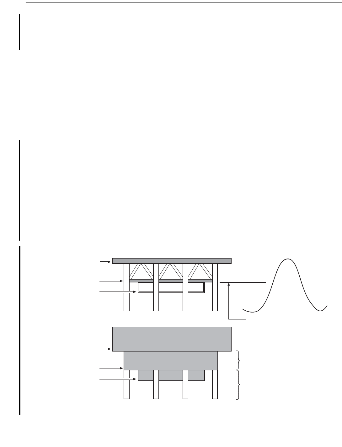
Figure C17.6.2-1a—Silhouette Area Definition
Main Deck
Cellar Deck
Scaffold Deck
Main Deck
Elevation View of Platform Deck
Wave
Deck legs and braces
are part of deck area
Elevation of underside
of cellar deck used for
inadequate deck height
trigger.
Deck legs and braces
are part of jacket
Cellar Deck
Scaffold Deck
05
Copyright American Petroleum Institute
Provided by IHS under license with API
Licensee=Indonesia location/5940240008
Not for Resale, 10/22/2008 00:07:12 MDT
--`,,```,,,`,,,,,,,,,,,,,,`,``,`-`-`,,`,,`,`,,`---

RECOMMENDED PRACTICE FOR PLANNING, DESIGNING AND CONSTRUCTING FIXED OFFSHORE PLATFORMS—WORKING STRESS DESIGN 255
g. Soil data.
h. Number, size, and design penetration of piles and
conductors.
i. Appurtenances—list and location as designed.
3. Construction:
a. Fabrication and installation contractors and date of
installation.
b. “As-built” drawings.
c. Fabrication, welding, and construction specifica-
tions.
d. Material traceability records.
e. Pile and conductor driving records.
f. Pile grouting records, (if applicable).
4. Platform history:
a. Environmental loading history—hurricanes, earth-
quakes, etc.
b. Operational loading history—collisions and acci-
dental loads.
c. Survey and maintenance records.
d. Repairs—descriptions, analyses, drawings, and
dates.
e. Modifications—descriptions, analyses, drawings,
and dates.
5. Present condition:
a. All decks—actual size, location and elevation.
b. All decks—existing loading and equipment
arrangement.
c. Field measured deck clearance elevation (bottom of
steel).
d. Production and storage inventory.
e. Appurtenances—current list, sizes, and locations.
f. Wells—number, size, and location of existing
conductors.
g. Recent above-water survey (Level I).
h. Recent underwater platform survey (Level II mini-
mum).
If original design data, or as-built drawings are not avail-
able, assessment data may be obtained by field measurements
of dimensions and sizes of important structural members and
appurtenances. The thickness of tubular members can be
determined by ultrasonic procedures, both above and below
water, for all members except the piles. When the wall thick-
ness and penetration of the piles cannot be determined and
the foundation is a critical element in the structural adequacy,
it may not be possible to perform an assessment. In this case,
it may be necessary to downgrade the use of the platform to a
lower assessment category by reducing the risk or to demon-
strate adequacy by prior exposure.
C17.4.3 Soil Data
Many sampling techniques and laboratory testing proce-
dures have been used over the years to develop soil strength
parameters. With good engineering judgment, parameters
developed with earlier techniques may be upgraded based on
published correlations. For example, design undrained shear
strength profiles developed for many platforms installed prior
to the 1970s were based on unconfined compression tests on
2.25-inch diameter driven wireline samples. Generally speak-
ing, unconfined compression (UC) tests give lower strength
values and greater scatter than unconsolidated undrained
compression (UU) tests, which are now considered the stan-
dard (see Section 6). Studies have also shown that a 2.25-inch
sampler produces greater disturbance than the 3.0-inch diam-
eter thin-walled push samplers now typically used offshore.
Therefore, depending on the type of sampling and testing
associated with the available data, it may be appropriate to
adjust the undrained shear strength values accordingly.
Pile-driving data may be used to provide additional insight
on the soil profiles at each pile location, and to infer the ele-
vations of pile end bearing strata.
C17.5 ASSESSMENT PROCESS
C17.5.1 General
Acceptable alternative assessment procedures include:
1. Assessment of similar platform by comparison:
Design level or ultimate strength performance charac-
teristics from an assessment of one platform may be
used to infer the fitness for purpose of other similar
platforms, provided the platforms’ framing, foundation
support, service history, structural condition, and pay-
load levels are not significantly different. In cases
where one platform’s detailed performance characteris-
tics are used to infer those of another similar platform,
documentation should be developed to substantiate the
use of such generic data.
2. Assessment with explicit probabilities of failure: As
an alternative to meeting the requirements herein, the
computation of explicit probabilities of platform fail-
ure may be performed at the discretion of the owner,
provided the failure probabilities are properly derived,
and the acceptance criteria used can be satisfactorily
substantiated.
3.
Assessment based on prior exposure: A
nother alter-
native to meeting the requirements herein for metocean
loading assessment is to use prior storm exposure, pro-
vided the platform has survived with no significant
damage. The procedure would be to determine, from
either measurements or calibrated hind-casts, the
Copyright American Petroleum Institute
Provided by IHS under license with API
Licensee=Indonesia location/5940240008
Not for Resale, 10/22/2008 00:07:12 MDT
--`,,```,,,`,,,,,,,,,,,,,,`,``,`-`-`,,`,,`,`,,`---

256 API RECOMMENDED PRACTICE 2A-WSD
expected maximum base shear to which the platform
has been exposed, and then check to see if it exceeds,
by an appropriate margin, the base shear implied in the
ultimate strength analysis check. The margin will
depend on the uncertainty of the exposure wave forces,
the uncertainty in platform ultimate strength, and the
degree to which the platform’s weakest direction was
tested by the exposure forces. All sources of uncer-
tainty, (that is, both natural variability and modeling
uncertainty), should be taken into account. The margin
has to be substantiated by appropriate calculations to
show that it meets the acceptance requirements herein.
Analogous procedures may be used to assess existing
platforms based on prior exposure to seismic or ice
loading.
C17.5.2 Assessment for Metocean Loading
The A-1 life safety manned-nonevacuated criteria are not
typically applicable to the U.S. Gulf of Mexico. Current
industry practice is to evacuate platforms for hurricanes
whenever possible. Should this practice not be possible for a
U.S. Gulf of Mexico platform under assessment, alternative
criteria would need to be developed to provide adequate life
safety. The A-2 life safety manned-evacuated criteria provide
safety of personnel for hurricanes that originate inside the
U.S. Gulf of Mexico, where evacuation may not be assured
(for example, Hurricane Juan (1985)). The A-3 life safety
manned-evacuated criteria also encompass winter storms.
In the U.S. Gulf of Mexico, many early platforms were
designed to 25-year return period conditions, resulting in low
deck heights. By explicitly specifying wave height, deck
inundation forces can be estimated directly for ultimate
strength analysis (see Section 17.6).
C17.5.3 Assessment for Seismic Loading
An alternative basis for seismic assessment is outlined in
the API-sponsored Report titled: “Seismic Safety Requalifi-
cation of Offshore Platforms,” by W.D. Iwan, et. al., May
1992. This report was prepared by an independent panel
whose members were selected based on their preeminence in
the field of earthquake engineering and their experience in
establishing practical guidelines for bridges, buildings, and
other onland industrial structures. The basis for separating
economic, life safety, and environmental safety issues is
addressed in this report.
C17.6 METOCEAN, SEISMIC AND ICE CRITERIA/
LOADS
C17.6.2 Wave/Current Deck Force Calculation
Procedure
The procedure described herein is a simple method for pre-
dicting the global wave/current forces on platform decks. The
deck force procedure is calibrated to deck forces measured in
wave tank tests in which hurricane and winter storm waves
were modeled.
The result of applying this procedure is the magnitude
and point-of-application of the horizontal deck force for a
given wave direction. The variability of the deck force for a
given wave height is rather large. The coefficient of varia-
tion (that is, standard deviation divided by the mean) is
about 0.35. The deck force should be added to the associ-
ated wave force.
Other wave/current deck force calculation procedures for
static and/or dynamic analyses may be used provided they are
validated with reliable and appropriate measurements of glo-
bal wave/current forces on decks either in the laboratory or in
the field.
The deck force procedure relies on a calculated crest
height. The crest height should be calculated using the wave
theory as recommended in Section 2.3.1b.2, and the ultimate
strength analysis wave height, associated wave period, and
storm tide.
The steps for computing the deck force and its point of
application are as follows:
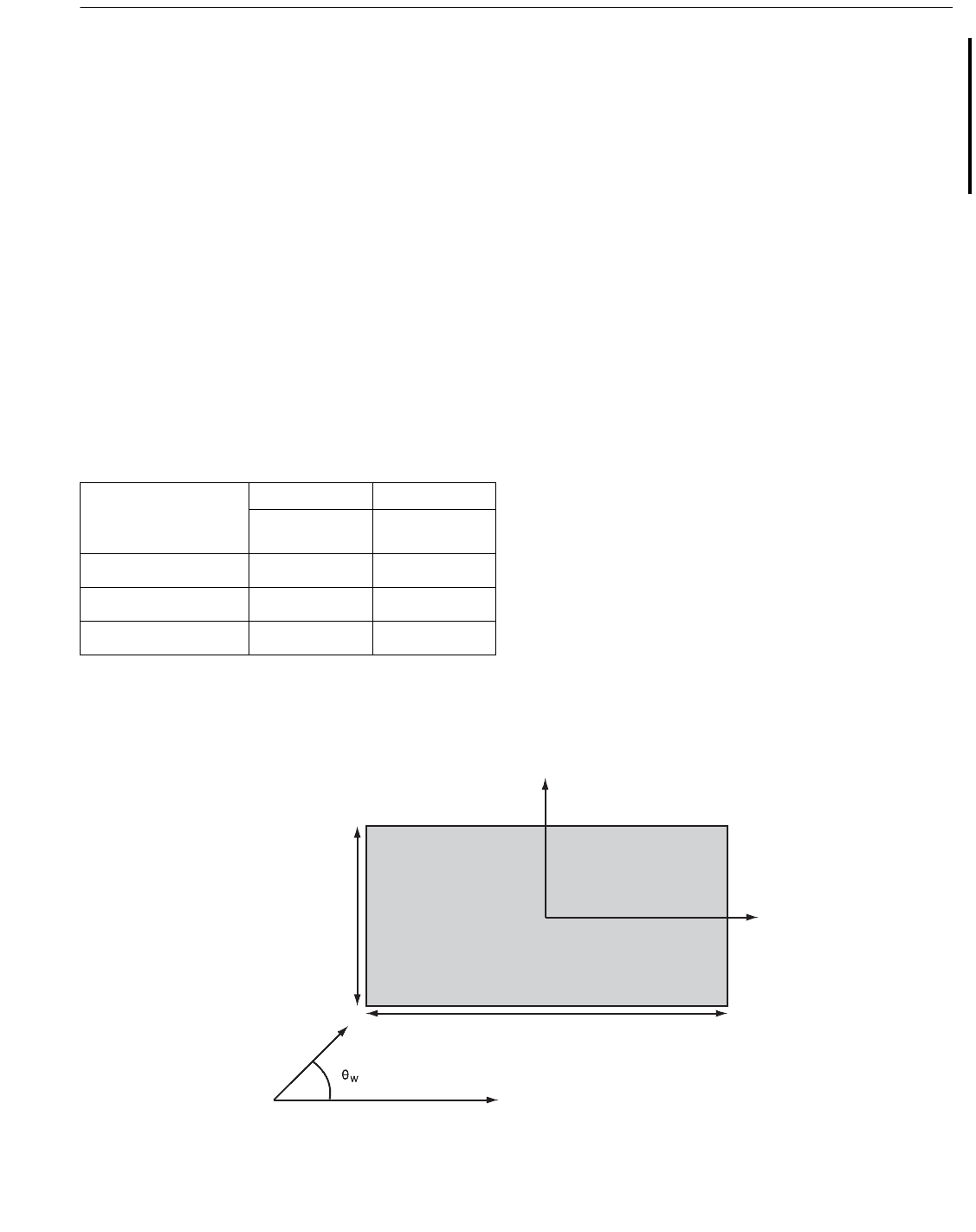
a. Step 1: Given the crest height, compute the wetted “sil-
houette” deck area, (A) projected in the wave direction, (θ
w
).
The full silhouette area for a deck is defined as the shaded
area in Figure C17.6.2-1a, i.e., the area between the bottom of
the scaffold deck and the top of the “solid” equipment on the
main deck. The silhouette area for deck force calculations is a
subset of the full area, extending up to the “crest elevation.”
This is an elevation above mllw that is equal to the sum of the
storm tide and crest height required for ultimate strength anal-
ysis. The silhouette area is therefore equal to the distance
between the underside of the deck and the crest elevation,
times the deck width.
For lightly framed sub-cellar deck sections with no equip-
ment (for example, a scaffold deck comprised of angle iron),
use one-half of the silhouette area for that portion of the full
area. The areas of the deck legs and bracing above the cellar
deck are part of the silhouette area. Deck legs and bracing
members below the bottom of the cellar deck should be mod-
eled along with jacket members in the jacket force calculation
procedure. Lattice structures extending above the “solid
equipment” on the main deck can be ignored in the silhouette.
The area, A, is computed as follows:
A = A
x
cos θ
w
+ A
y
sin θ
w
where:
θ
w
, A
x
and A
y
are as defined in Figure C17.6.2-1b.
b. Step 2: Use the wave theory recommended in Section
2.3.1 or C2.3.1, and calculate the maximum wave-induced
horizontal fluid velocity, V, at the crest elevation or the top of
the main deck silhouette, whichever is lower.
05
07
Copyright American Petroleum Institute
Provided by IHS under license with API
Licensee=Indonesia location/5940240008
Not for Resale, 10/22/2008 00:07:12 MDT
No reproduction or networking permitted without license from IHS
RECOMMENDED PRACTICE FOR PLANNING, DESIGNING AND CONSTRUCTING FIXED OFFSHORE PLATFORMS—WORKING STRESS DESIGN 257
c. Step 3: The wave/current force on the deck, F
dk
, is com-
puted by the following:
F
dk
=
1
/
2
ρ C
d
(a
wkƒ
• V + α
cbƒ
• U)
2
A,
where:
U = the current speed in-line with the wave,
a
wkƒ
= the wave kinematics factor (0.88 for hurricanes
and 1.0 for winter storms),
a
cbƒ
= the current blockage factor for the jacket,
ρ = the mass density of seawater.
The drag coefficient, C
d
, is given in Table C17.6.2-1.
d. Step 4: The force F
dk
should be applied at an elevation Z
dk
above the bottom of the cellar deck. Z
dk
is defined as 50 per-
cent of the distance between the lowest point of the silhouette
area and the lower of the wave crest or top of the main deck.
C17.6.2a U.S. Gulf of Mexico Criteria
The A-1 criteria are based on the “full population” hurri-
canes (all hurricanes affecting the U.S. Gulf of Mexico). A-2
criteria are based on a combined population consisting of
“sudden” hurricanes (subset of full population hurricanes)
and winter storms. The A-3 criteria are based on winter
storms.
The sudden hurricane criteria are based on hurricanes that
spawn in the U.S. Gulf of Mexico. These criteria apply to
manned platforms in which there may not be enough warning
to evacuate. Hurricanes that spawn outside the U.S. Gulf of
Mexico were not included because sufficient warning to
evacuate all platforms is available provided that conventional
evacuation procedures are maintained. An example of a sud-
den hurricane is Juan (1985). The sudden hurricane popula-
tion used here provides for conservative criteria because,
among the 27 hurricanes that spawned in the U.S. Gulf of
Mexico during 1900–1989, platforms would have been evac-
uated in almost all cases.
C17.7 STRUCTURAL ANALYSIS FOR
ASSESSMENT
C17.7.1 General
Structural evaluation is intended to be performed in three
consecutive levels of increasing complexity. Should a struc-
ture fail the screening or first level, it should be analyzed
using the second level, and similarly for the third level. Con-
versely, should a structure pass screening, no further analysis
is required, and similarly for the second level. The first level
(screening) is comprised of the first four components of the
assessment process: (1) selection, (2) categorization, (3) con-
dition assessment, and (4) design basis checks. The second
Table C17.6.2-1—Drag Coefficient, C
d
, for Wave/
Current Platform Deck Forces
Deck Type
C
d
C
d
End-on and
Broadside Diagonal (45°)
Heavily equipped (solid) 2.5 1.9
Moderately equipped 2.0 1.5
Bare (no equipment) 1.6 1.2
Plan view of deck
Wave
heading
A
x
A
y
Y
X
Figure C17.6.2-1b—Wave Heading and Direction Convention
05
Copyright American Petroleum Institute
Provided by IHS under license with API
Licensee=Indonesia location/5940240008
Not for Resale, 10/22/2008 00:07:12 MDT
No reproduction or networking permitted without license from IHS

258 API RECOMMENDED PRACTICE 2A-WSD
level (design level analysis) allows recognition of the work-
ing strength of a member or joint within the elastic range
using current technology. The third level (ultimate strength
analysis) recognizes the full strength of the platform structure
to demonstrate adequacy and stability.
C17.7.2 Design Level Analysis Procedures
C.17.7.2a General
It should be noted that the design level analysis criteria
provided in Section 17.6 were calibrated for structures that
did not have wave loading on their decks. It is therefore
unconservative to consider wave loading on decks for assess-
ments using design level analysis. Ultimate strength analysis
is required instead, using the higher environmental criteria
contained in Section 17.6. Note that for some wave-in-deck
loading, only a linear global analysis will be necessary (see
Section 17.7.3a).
C.17.7.2b Structural Steel Design
Should ongoing research be used to determine the strength
of members, it must be carefully evaluated to assure applica-
bility to the type of member, its level of stress, and the level
of confidence in the conclusions of the research. For exam-
ple, the use of smaller values for effective length (K) factors
might be appropriate for members developing large end
moments and high levels of stress, but might not be appropri-
ate for lower levels of stress.
Because of availability and other nonstructural reasons,
members could have steel with yield stress higher than the
specified minimum. If no such data exist, tests can be used
to determine the actual yield stress. Joint industry studies
have indicated that higher yield stresses can be justified sta-
tistically.
C.17.7.2c Connections
Joints are usually assumed rigid in the global structural
model. Significant redistribution of member forces can result
if joint flexibility is accounted for, especially for short brac-
ing with small length-to-depth ratios, and for large leg can
diameters where skirt piles are used. Joint flexibility analysis
may use finite element methods as appropriate. Steel joints
can have higher strength than currently accounted for. Simi-
larly, the evaluation of strength for grouted joints, as well as
the assessment of grout stiffness and strength, may consider
higher values than normally used for design.
C.17.7.2d Fatigue
All offshore structures, regardless of location, are subject
to fatigue degradation. In many areas, fatigue is a major
design consideration due to relatively high ratios of opera-
tional seastates to maximum design environmental events. In
the U.S. Gulf of Mexico, however, this ratio is low. Still,
fatigue effects should be considered and engineering deci-
sions should be consciously based on the results of any
fatigue evaluations.
Selection of critical areas for any Level III and/or IV
inspections should preferably be based on factors such as
joint and member loads, stresses, stress concentration, struc-
tural redundancy, and fatigue lives as determined by platform
design.
In the U.S. Gulf of Mexico, Level III and/or IV underwater
surveys may be considered adequate if they indicate no
fatigue cracks. Should cracks be indicated, no further analysis
is required if these are repaired. The use of analytical proce-
dures for the evaluation of fatigue can be adequate if only
Level II survey is done.
C17.7.3 Ultimate Strength Procedures
It should be noted that limited structural damage is accept-
able and that the more severe environmental loading as noted
in Section 17.6 is required.
In ultimate strength analysis, structural elements are
allowed to carry loads up to their ultimate capacities, they can
continue to carry load after reaching those capacities, depend-
ing on their ductility and post-elastic behavior. Such elements
may exhibit signs of damage, having crossed over buckling
or inelastic yielding. In this context, damage is acceptable as
long as the integrity of the structure against collapse is not
compromised.
Since structures do not usually develop overload stresses in
most of their elements at one time, the need to perform com-
plex ultimate strength analyses for the whole structure might
not be justified for a few overloaded elements, thus the need
to distinguish between local and global overloading.
An efficient approach to ultimate capacity assessment is to
carry it out in a step-wise procedure as follows: (a) perform a
linear global analysis to determine whether nonlinearity is a
local or a global problem, and (b) perform local or global ulti-
mate strength analysis as required.
As an alternative to a nonlinear assessment such as a push-
over analysis, it may be possible to demonstrate that the plat-
form will pass the ultimate strength assessment by using a
linear elastic analysis, similar to a design level analysis, with
the exception that the typical factors of safety associated with
axial, bending, shear and other loading conditions have been
removed. Other known sources of conservatism such as the
use of mean yield strength instead of nominal yield strength
may also be taken into account. The intent is to approximate
performance of the platform members when loads are above
allowable stress but below actual yield or buckling. If all of
the platform members can be shown to remain elastic, consid-
ering all combined stress states, then the platform passes the
ultimate strength assessment. If the load in a platform mem-
ber or members exce
eds yield, then a nonlinear ultimate
strength analysis should be utilized.
05
Copyright American Petroleum Institute
Provided by IHS under license with API
Licensee=Indonesia location/5940240008
Not for Resale, 10/22/2008 00:07:12 MDT
No reproduction or networking permitted without license from IHS