Amano R.S., Sunden B. (Eds.) Computational Fluid Dynamics and Heat Transfer: Emerging Topics
Подождите немного. Документ загружается.

Sunden ch003.tex 27/8/2010 18: 35 Page 106
106 Computational Fluid Dynamics and Heat Transfer
φ/φ
0
= 0.75 φ/φ
0
= 1.07 φ/φ
0
= 1.25
Turbulence viscosity
Turbulence viscosity
Turbulence viscosity
100
65
2000
1525
1050
575
100
[Pa s]
60
55
50
45
75
50
25
0
[Pa s]
Figure 3.40. Turbulent viscosity (µ
τ
/µ) contours at midplane of volute.
(a) (b) (c)
Figure 3.41. Velocity vector at θ =180 degrees (φ/φ
0
=1.07). (a) Sharp tongue
(zero-equation model) (b) Rounded tongue (zero-equation model)
(c) Rounded tongue (k-ε model).
(a) (b) (c)
Figure 3.42. Velocityvectoratscrollexit(θ =360degrees(φ/φ
0
=1.07).(a)Sharp
tongue (zero-equation model); (b) Rounded tongue (zero-equation
model); (c) Rounded tongue (k-ε model).
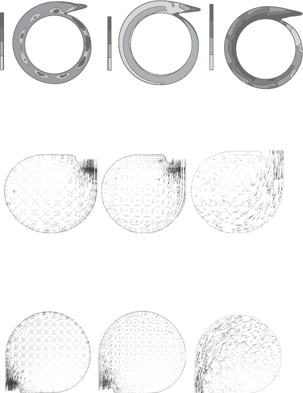
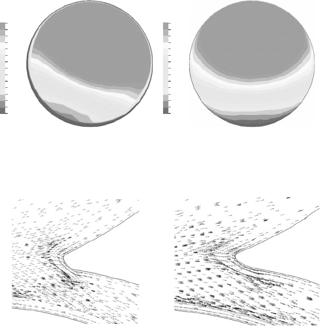
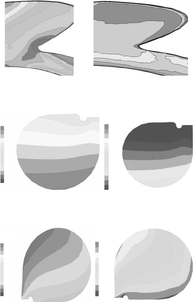
In the investigation of the tongue shape influence of the compressor, the sharp
tongue scroll model was analyzed by using the zero-equation turbulence model.
Figures3.41 and42 show secondary flowvectors atcross sectionsθ =180 and 360
degreesforasharptongueandaroundedtonguescrollsatadesignflowcondition.It
canbeseenthatthesecondaryflowinthescrollsectionshasasinglevortexstructure
Sunden ch003.tex 27/8/2010 18: 35 Page 107
CFD for industrial turbomachinery designs 107
(a) (b)
Tongue
Tongue
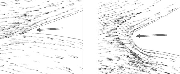
Figure 3.43. Velocity vectors near tongue intersection at midplane (φ/φ
0
=1.07).
(a) Sharp tongue. (b) Rounded tongue.
in both tongue geometries. It can also be seen that the tongue shape changes the
secondary flow structures. The secondary flow impacted by the tongue occurs not
onlynearthetongueareabutalsoinothersectionsofthescroll.Theroundedtongue
createsarelativelylargeblockagenearthetonguearea.Thelargeblockageforcesthe
secondary flow center away from the tongue area.At both θ =180 and 360 degree
locations, the secondary flow is stronger for the rounded tongue compared with
the sharp tongue. The secondar y flow center for sharp tongue occurs in the region
closertothe tonguecomparedwiththat fortheroundedtongue.Ascanbeobserved
in these figures, the difference between the two turbulence models is very small.
Theflowstructuresnearthetonguesaresimilarforbothtonguesatadesignflow
condition seen in Figure 3.43. The flow leaves the tongue leading edge smoothly
at a design flow rate for both cases. No separation zone is found. It is also found
thatthe sharptongue hasasmaller blockagethantheroundedtongue (Figure3.43).
The flow near the leading edge of the rounded tongue is blockedby the tongue and
then pushed away from the tongue.
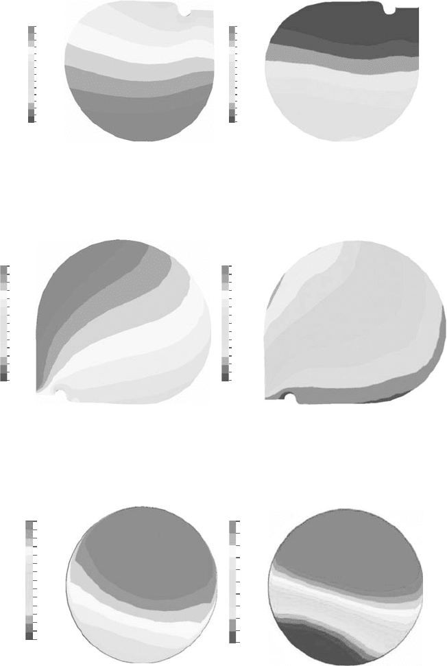
Figures 3.44 and 45 show computed static pressure contours for the scroll with
rounded tongue near the design flow rate at cross sections θ =180 degree and 360
degreeatadesignconditionwithdifferentturbulencemodels.Figure3.46showsthe
exitplane totalpressure contoursat the designcondition. It canbe seenthat thek-ε
turbulencemodelpredictedlowerstaticpressureandhighertotalpressure.However,
the differences of the mass average pressures are less than 1%, as indication in
Figure 3.46. The total pressure distributions are asymmetrical for both cases, and
the symmetrical total pressure distributions are caused by secondary flows. The
location of the highest total pressure range is different for the two calculations.
It is attributed to the usage of the different turbulence models, which resulted in
different secondary flow predictions.
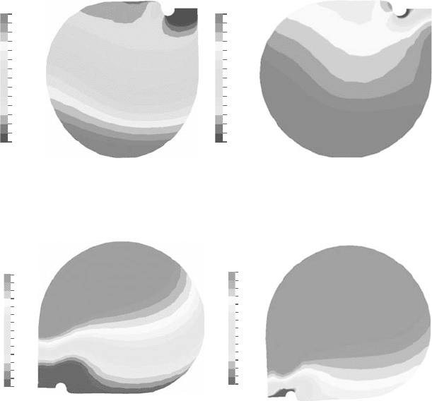
Figure3.47showsthevelocityvectorsnearthetongueintersectionatamidplane
and the secondary velocity vectors near the tongue trailing edge near the choke
flowrateφ/φ
0
=1.25.It isobservedthattheflowsseparatenearthe tonguefor both
Sunden ch003.tex 27/8/2010 18: 35 Page 108
108 Computational Fluid Dynamics and Heat Transfer
(a) (b)
350000
349786
349571
349357
349143
348929
348714
348500
348286
348071
347857
347643
347429
347214
347000
[Pa]
Pressure Pressure
350000
349786
349571
349357
349143
348929
348714
348500
348286
348071
347857
347643
347429
347214
347000
[Pa]
Figure 3.44. Static pressure contour at θ =180 degree (φ/φ
0
=1.07). (a) Zero-
equation model. (b) k-ε model.
349,000
348,786
348,571
348,357
348,143
347,929
347,714
347,500
347,286
347,071
346,857
346,643
346,429
346,214
346,000
[Pa]
Pressure
(a) (b)
349,000
348,786
348,571
348,357
348,143
347,929
347,714
347,500
347,286
347,071
346,857
346,643
346,429
346,214
346,000
[Pa]
Pressure
Figure 3.45. Static pressure contour at scroll exit (θ =360 degree (φ/φ
0
=1.07).
(a) Zero-equation model. (b) k-ε model.
Total pressure
(a) (b)
Total pressure
350,300
350,200
350,150
350,100
350,050
350,000
359,950
359,900
359,850
359,800
359,750
359,700
359,650
359,500
350,250
350,300
350,230
350,160
350,090
350,020
349,950
349,880
349,810
349,740
349,670
349,600
Figure 3.46. Total pressure contour at discharge of the exit cone (φ/φ
0
=1.07).
(a) Zero-equation model. (b) k-ε model.

Sunden ch003.tex 27/8/2010 18: 35 Page 109
CFD for industrial turbomachinery designs 109
(a) (b)
Figure 3.47. Velocity vectors near tongue intersection at midplane (φ/φ
0
=1.25).
(a) Zero-equation model. (b) k-ε model.
Total pressure
(a) (b)
[Pa]
250,000
249,444
248,889
248,333
247,778
247,222
246,667
246,111
245,556
245,000
Total pressure
[Pa]
250,000
249,444
248,889
248,333
247,778
247,222
246,667
246,111
245,556
245,000
Figure 3.48. Total pressure contours near tongue intersection at midplane
(φ/φ
0
=1.25). (a) Zero-equation model. (b) k-ε model.
cases.Thescroll tongueencounters alarge incidencebecause highflow rateresults
in large flow angles from the tangential direction.A large incidence results in flow
separations from near the leading edge of the tongue. The k-ε turbulence model
predicts a recirculation zone near the inlet of the volute, and the zero-equation
turbulence model predicts a larger recirculation zone.Total pressure contours near
the tongue intersection at midplane are shown in Figure 3.48.
Total pressure distributions near the tongue are different between two different
turbulence model predictions. The zero-equation model predicts the lowest total
pressure zone near the tongue. However, the k-ε turbulence model predicts the
lowesttotalpressureintheregion,whichislocatednearthevoluteinlettonguearea.
Sunden ch003.tex 27/8/2010 18: 35 Page 110
110 Computational Fluid Dynamics and Heat Transfer
Pressure
[Pa]
145,000
144,786
144,571
144,357
144,143
143,929
143,714
143,500
143,286
143,071
142,857
142,643
142,429
142,214
142,000
Pressure
(a) (b)
[Pa]
145,000
144,786
144,571
144,357
144,143
143,929
143,714
143,500
143,286
143,071
142,857
142,643
142,429
142,214
142,000
Figure 3.49. Static pressure at choke flow at θ =180 degrees (φ/φ
0
=1.25).
(a) Zero-equation model. (b) k-ε model.
Pressure Pressure
140,000
139,786
139,571
139,357
139,143
138,929
138,714
138,500
138,286
138,071
137,857
137,643
137,429
137,214
137,000
140,000
139,786
139,571
139,357
139,143
138,929
138,714
138,500
138,286
138,071
137,857
137,643
137,429
137,214
137,000
[Pa] [Pa]
(a) (b)
Figure 3.50. Static pressure at choke flow at θ =360 deg ree (φ/φ
0
=1.25).
(a) Zero-equation model. (b) k-ε model.
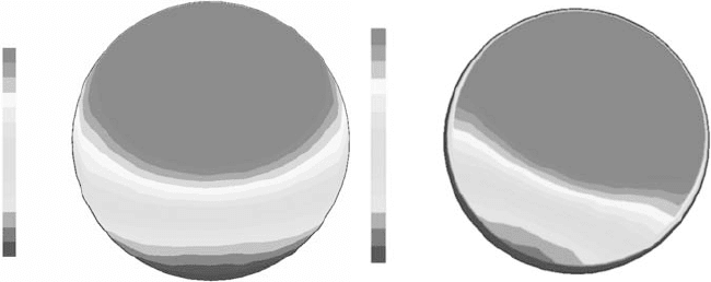
The computed static pressure contours near the choke flow rate at cross sections
θ =180 and 360 degrees are shown in Figures 3.49 and 50. It can be seen that the
k-ε model predicted higher static pressure level than the zero-equation model.The
total pressure distributions at the scroll exit are shown in Figure 3.51. The total
pressure level predicted using the k-ε model is higher than that using the zero-
equation model.The lowest total pressure zone location appears to be different for
the two computational cases.This is because these two turbulence models result in
differentstrengths of the secondary flow. The total pressure distributions predicted
using the k-ε model showed the boundary-layer effects; that is, there is a lower
total pressure zone around the discharge pipe wall. Figure 3.52 shows velocity
vectorsnearthetongueintersectionatmidplanenearthesurgeflowrateφ/φ
0
=0.75.
Flowvectorsnear thetongueindicate acontinuousflow passingthroughthetongue
and into the exit duct. Flow vectors also indicate that due to the large recirculation
flow, the pressure side of the tongue does not show significant flow separation.
The large cutback tongue withsignificant flow circulation inside thescroll part can
delay the flow separation near scroll tongue at a small flow rate. Two types of the
Sunden ch003.tex 27/8/2010 18: 35 Page 111
CFD for industrial turbomachinery designs 111
Total pressure
(a) (b)
[Pa]
145,300
144,893
144,486
144,079
143,671
143,264
142,857
142,450
142,043
141,636
141,229
140,821
140,414
140,007
139,600
Total pressure
[Pa]
145,300
144,893
144,486
144,079
143,671
143,264
142,857
142,450
142,043
141,636
141,229
140,821
140,414
140,007
139,600
Figure 3.51. Total pressure discharge of exit cone at choke flow (φ/φ
0
=1.25).
(a) Zero-equation model. (b) k-ε model.
(a) (b)
Figure 3.52. Velocity vectors near intersect diffuser and tongue near surge condi-
tion (φ/φ
0
=0.75). (a) Zero-equation model. (b) k-ε model.
turbulence model provided very similar results. Total pressure distributions near
the scroll tongue at the midplane area are shown in Figure 3.53. Total pressure
distributions show that the k-ε model predicted a slightly higher level of the total
pressure.The performance test also confirms this. Static pressure contours at cross
sections θ =180 and 360 degrees are shown in Figures 3.54 and 55. It is shown
that the k-ε model predicted a lower level of static pressure than the zero-equation
turbulencemodel.Total pressuredistributionsas shownin Figure 3.56indicatethat
the k-ε model predicted higher total pressure levels than the zero-equation model.
However,the differencesbetweentwocalculations areinsignificantlysmall.Again,
the boundary-layer effects can be seen in the k-ε turbulence model calculations.
The calculations showed that, by using different turbulence models, the perfor-
mance prediction results did not make significant difference. In these calculations,
the impeller and the vaned diffuser as well as scroll tongue have relatively sharp
Sunden ch003.tex 27/8/2010 18: 35 Page 112
112 Computational Fluid Dynamics and Heat Transfer
(a) (b)
Figure 3.53. Total pressure contours near tongue intersection at midplane
(φ/φ
0
=0.75). (a) Zero-equation model. (b) k-ε model.
[Pa]
[Pa]
Pressure
(a) (b)
Pressure (ps180)
405,000
404,786
404,571
404,357
404,143
403,929
403,714
403,500
403,286
403,071
402,857
402,643
402,429
402,214
402,000
405,000
404,786
404,571
404,357
404,143
403,929
403,714
403,500
403,286
403,071
402,857
402,643
402,429
402,214
402,000
Figure 3.54. Static pressure at surge condition at θ =180 degrees (φ/φ
0
=0.75).
(a) Zero-equation model. (b) k-ε model.
[Pa]
Pressure
405,000
404,786
404,571
404,357
404,143
403,929
403,714
403,500
403,286
403,071
402,857
402,643
402,429
402,214
402,000
[Pa]
Pressure (ps360)
3.490e+05
3.487e+05
3.484e+05
3.481e+05
3.478e+05
3.475e+05
3.472e+05
3.469e+05
3.466e+05
3.463e+05
3.460e+05
(a) (b)
Figure 3.55. Static pressure at surge flow at θ =360 degrees (φ/φ
0
=0.75).
(a) Zero-equation model. (b) k-ε model.
Sunden ch003.tex 27/8/2010 18: 35 Page 113
CFD for industrial turbomachinery designs 113
[Pa]
Total pressure
(a) (b)
405,800
405,814
405,829
405,843
405,857
405,871
405,886
405,900
405,914
405,929
405,943
405,957
405,971
405,986
406,000
[Pa]
Total pressure
405,800
405,814
405,829
405,843
405,857
405,871
405,886
405,900
405,914
405,929
405,943
405,957
405,971
405,986
406,000
Figure 3.56. Total pressure discharge of exit cone at surge flow (φ/φ
0
=0.75).
(a) Zero-equation model. (b) k-ε model.
leading edges. The flow losses may mainly be dependent on the flow angle
separations; this type of flow separation is not sensitive to the turbulence models.
3.10 CFDApplications inTurbomachine Design
With the development of the computer hardware, the CFD has been implemented
intheturbomachine designprocess.Enormouseffortsaredevotedtoimprovingthe
efficiency of the gas turbine components. The designs for turbine and compressor
airfoils play one of the most important roles in increasing the turbine efficiency. In
the airfoil design, there are two types of implementations the aerodynamic design
engineeroftenconsiders. Oneistodesignandemploycustom-designbladeprofiles
with minimum losses and controlled blade boundary-layers. The second and even
more complex part is to minimize losses resulting from secondary flows near hub
and casing. Recently three-dimensional blade design concepts that help to control
secondaryflowswereproposed[1].However,thecomplexflowisdifficultevenwith
fullythree-dimensional Navier–Stokes flow solvers.And the validation of the N–S
solvers need to take large numbers of experimental data, which is time consuming
andexpensive.Therefore,almostall theaerodynamicdesignsare basedonthetwo-
dimensional design.Theinviscous analysesof the two-dimensionalairfoil sections
still play an important role in the design process.
It is known that for a blade row in an annulus, the stream surface between two
annular walls is twisted for most cases. These twists are induced by either shed
vorticity or Secondary flow arising from. Stream surface twist can arise in an irro-
tational flow owing to either spanwise components of velocity or spanwise blade
forces. Many efforts have been taken to reduce the stream surface twist and the
secondary flow losses, such as sweep, lean, bow, and twist the blades or design an
asymmetric end wall. However, there is little information availablein the literature
for using three-dimensional design and almost no information available to show
howto integratethe three-dimensionalfeaturesinto thedesignprocess. Mostofthe
Sunden ch003.tex 27/8/2010 18: 35 Page 114
114 Computational Fluid Dynamics and Heat Transfer
turbomachinery design system investigations were still on the academic research
andwerebased onthe particular machinesor blades.Moreover, most ofthe studies
were based on the particular blade and flow situations. For example, Singh et al.
[14] argued that closing the blade throat near theend walls couldobtain significant
efficiency improvements, and Wallis and Denton [20] also obtained an efficiency
increase from almost the opposite type of blade twist near the end wall. For dif-
ferent machines and different designs, many different techniques should be used
according to the flow field nature of the designs. It is very important to design a
blade design procedure and optimize the design.
The increased use of CFD tools has been driven mainly by two factors. First,
from performance standard point of view, efficiency has steadily increased. Sec-
ond, the turbomachinery industry as a whole has been pushed toward reduced cost
designs. The cost reduction is in terms of development, modification, production,
and operating costs.The cost reduction drives a turbomachinetoward high loading
in order to reduce stage count, while maintaining or exceeding past performance
goals. The current design of the new stage already is outside of the standard air-
foil database. Most of the airfoil needs to be designed. And the development of
the design toolsto meet this requirement becomescritical.The application of CFD
methodologytoimprovetheturbomachinerydesignisbecomingestablishedwithin
theturbomachinerycommunity.However, stillonly limitednumberofpublications
suggest how to useCFD to help design andmodify processes especiallyduring the
blade design. This chapter serves to present a design process that contains a novel
two- and three-dimensional viscous turbulent code and optimization process.
Expensive manpower is invested in order to find configurations that are sta-
ble and efficient in the work range in the turbine and compressor designs. One of
the most important methods is inverse design or called stream line design where
two-dimensional blade profiles are to be foundtoinsurethedesired working range
stabilityand efficiency. Duringthe design,the constraintsarising fromaerodynam-
ics, aeromechanical, mechanical, heat transfer, and manufacturing considerations
have to be satisfied.
The design of turbine and compressor blade had made a great progress. Many
advanced design methods and CFD tools have been incorporated into the design
procedure. However, most of the design procedures focus only on the flow pre-
diction, and there are few papers that describe the overall design processes and
design implements. For example, Wellborn and Delaney [5] described a com-
pressor design system in Rolls-Royce, which comprises three tools: through-flow,
three-dimensional isolated blade, and three-dimensional multistage predication.
The turbomachinery design is an integrated process that contains a process from
meanline, through-flow, airfoil design,and analysis.This paper developeda design
process that can be easily adapted by the industry.
Theaerodynamicdesignproceduresforturbomachineryairfoilusedinthisstudy
is shown in Figure 3.57. A design system includes meanline analysis, through-
flow analysis, airfoil section design, airfoil stackup, three-dimensional blade row,
and multistage flow analysis. For obtaining the highest design efficiency, the
optimizer was used to do the section optimization. The three-dimensional CFD
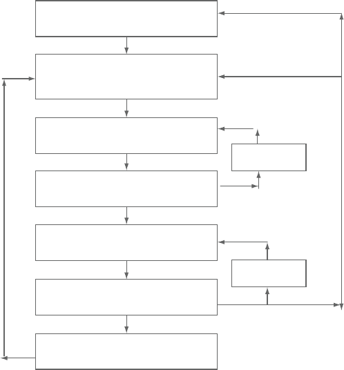
Sunden ch003.tex 27/8/2010 18: 35 Page 115
CFD for industrial turbomachinery designs 115
2D axisymmetric through-flow
analysis
Meanline analysis
3D blade row calculation
3D multistage calculation
Optimizer
Optimizer
Airfoil section design
Section viscous analysis
Airfoil stackup
Figure 3.57. Blade design and optimization procedure.
code was used for blade stackup optimization. The optimizer may be used for
three-dimensional blading although authors do not encourage the use of optimizer
for three-dimensional optimization.
Meanline analysis determines the loading of the stage and annular area. It
plays an important role in the turbomachinery design. The meanline design for
the first-stage compressor and the last-stage turbine is critical. The enthalpy rise
for compressor and dropfor turbine are fixedby the meanlineanalysis.The overall
machine character is determined by the meanline analysis. The compressor and
turbine efficiency is strongly influenced by meanline design.
Through-flow analysis is one of the preliminary design modules. The axisym-
metric streamline curvature calculations can be used to optimize the overall
parameters of a multistage turbomachine. This module establishes the definitions
of the flow path and work distributions in radio direction.The velocity diagrams at
design point for different bladerowsanddifferent streamlines are determined.The
optimization code can be used to do the optimization for selecting the best design
parameters, for example, stage loading and stage enthalpy change.