Altan T. Metal Forming Handbook
Подождите немного. Документ загружается.

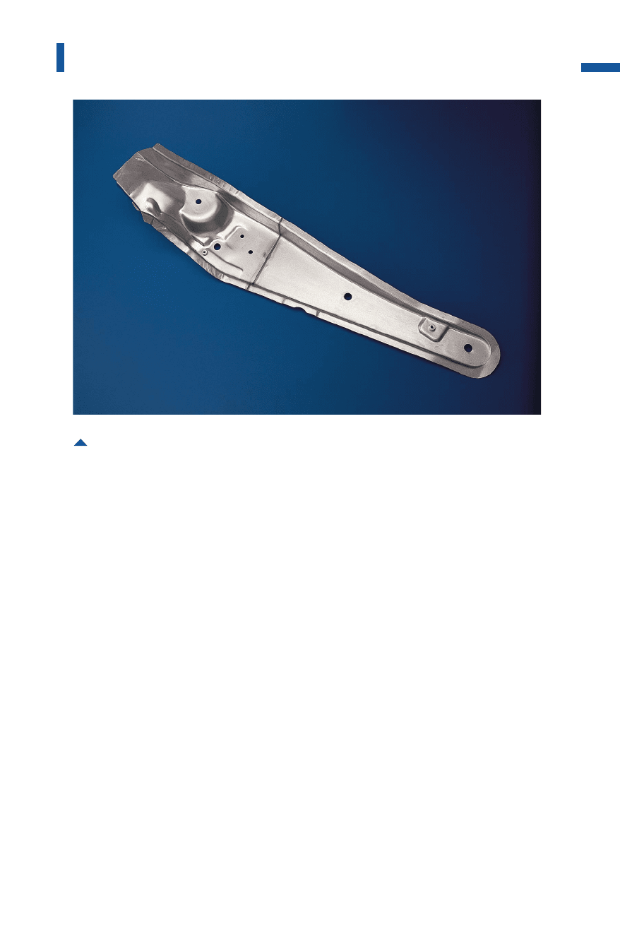
reinforcing components (Fig.4.6.24).In the production of complete
assemblies, this reduces lead times and the susceptibility to corrosion
due to the smaller number of welding joints.
By using scrap parts from previous blanking operations, for manu-
facturing tailored blanks it is possible to reduce scrap in the stamping
plant. Costs for input materials can also be reduced by using lower-cost
sheet metal grades for low-stress applications. In addition, tailored
blanks can be configured to special shapes for specific cases of applica-
tion. Such shapes are generally not offered by steel manufacturers.
These benefits have led to the widespread processing of tailored blanks.
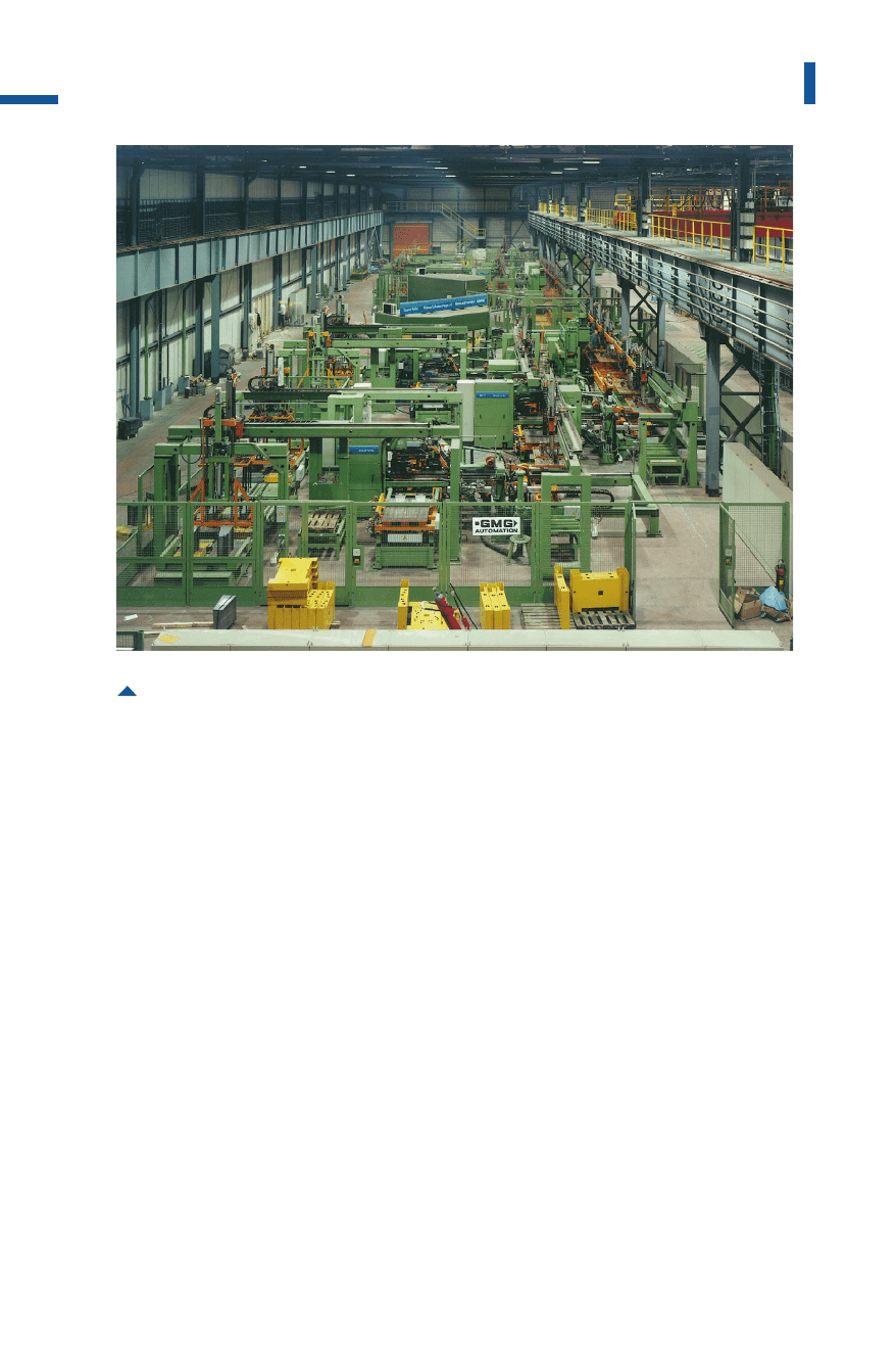
Tailored blanks are manufactured on blank welding lines (Fig. 4.6.25).
The blanks produced on a blanking press are loaded in stack form,
aligned, centered and fed to the automatic welding machine. The blanks
are then welded by means of resistance, laser or induction welding
methods (Fig. 4.6.26).
Where resistance welding is used, a control system checks the process,
assuming high output and quality. The welding unit comprises two
loading and centering tables for blank feed, a traversing unit to hold the
311
Shearing lines
Fig. 4.6.24 Passenger car reinforcement formed from a tailored blank
Metal Forming Handbook / Schuler (c) Springer-Verlag Berlin Heidelberg 1998
overlapping blanks together, and the stationary welding rolls. Alterna-
tively, the blanks can be stationary and the welding rolls may move.
Laser technology using CO
2
or solid lasers has proven successful as a
new production technology. However, when this method is used the
two sheet metal edges to be welded together must be prepared for the
welding process by laser cutting or by high-precision fine shearing.
Welding itself is performed with the blanks stationary and a mobile laser
focusing device or with moving blanks and a stationary focusing device.
The working speeds are comparable to those of a resistance welding
unit. In the case of coated sheet blanks, it is actually possible to achieve
higher working speeds. The benefit of laser welding is that no weld over-
fill occurs and even coated blanks can be processed without problems.
A third system, which is not yet used on an industrial scale, is
equipped with an induction welding unit. The blanks are pressed togeth-
er at the edges. The welding process itself is carried out at high speed, as
the blanks are joined over the entire length of their edges within about
312
Sheet metal forming and blanking
Fig. 4.6.25 Blank welding line with continuous part handling system for the manufacture of
welded side members
(cf. Fig. 4.4.12)
Metal Forming Handbook / Schuler (c) Springer-Verlag Berlin Heidelberg 1998
2s. The process cannot be executed on a continuous basis, as part trans-
port must be interrupted during welding.
After the welding process, the parts pass through the monitoring station
and the beading and oiling unit. The finished tailored blanks are then
stacked again and made ready for further processing in the forming line.
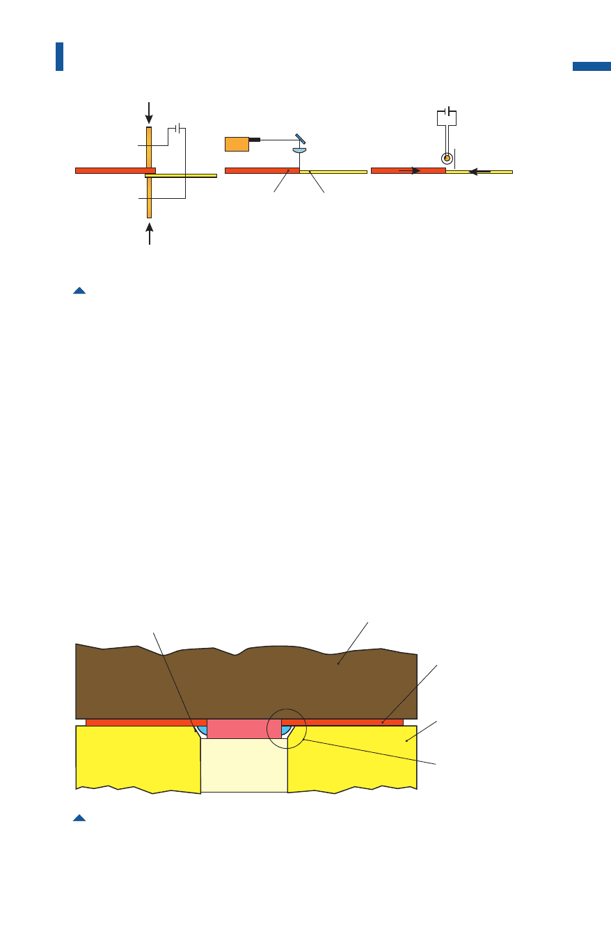
When deep drawing, depending on the position of the welded seam,
tailored blanks behave differently to conventional parts. If, for example,
the sheet metal thickness differs while the blank holder force remains
constant, wrinkles or tears can occur in the formed part. In these cases,
special blank holders which can be adjusted according to the formed
product, are used in the die set (Fig. 4.6.27).
313
Shearing lines
Fig. 4.6.26 Comparison of the principle layouts of resistance, laser and induction welding
systems
F
F
laserwelding inductionweldingresistancewelding
blank1 blank2
Fig. 4.6.27 Modified blank holder for deep drawing of tailored blanks
heightdifference
oftheblankholder
die
tailoredblank
segmented
blankholder
clearancefor
weldingseam
Metal Forming Handbook / Schuler (c) Springer-Verlag Berlin Heidelberg 1998

4.6.6Perforating presses
Perforated sheets are in widespread use in almost every sector of indus-
try: in the form of sieves and filters in the food industry, in mining and
gravel pits, as protective covers in the electrical industry, in building
machinery and machine tools, as partitions and for decorative purpos-
es, in household appliances, office furniture, aircraft and industrial con-
struction.
The number of punch contours and hole patterns is almost infinite.
Steel, NF metals or combinations are among the materials used, and sheet
thicknesses can range anywhere between 0.3 and 30mm. Perforated sheet
metal is manufactured either off the coil or in plate form. Basically, two
main methods are used: Continuous or periodically interrupted hole pat-
terns are manufactured in large series from coil or plate stock on all-across
perforating presses, while strip perforating presses are used for the small-
series production of optional hole patterns from plate material.
Both machine systems can be equipped with units for automatic
sheet metal feed, for removal of finished parts, notching, separating
and splitting, and with quick-action die changing devices, die monitor-
ing systems and sound enclosures.
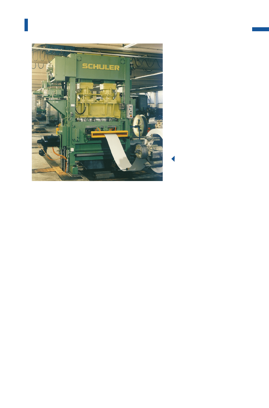
All-across perforating presses
Sheet metal with continuous or periodically repeated hole patterns are
manufactured on all-across perforating presses (Fig.4.6.28).These
presses process both coil and plate stock up to a thickness of around
6mm. The sheet metal runs through the press only in the feed direction
and is normally perforated in a single working stroke over the entire
width. The nominal press force lies between 800 and 5,000kN, the
maximum material width between 1,000 and 1,600mm. Depending on
the press size and feed system, all-across perforating presses operate at
up to 800 strokes per minute.
The press frame is configured as a monobloc (Fig.4.6.29).The slide
runs in clearance-free hardened roller gibs (cf.Fig.3.1.6)via two columns,
and is driven by a DC or threephase control motor via a flywheel, eccen-
tric shaft and two connecting rods. This configuration guarantees a long
die life. Short switching times, short stroke lengths and high resistance to
wear are achieved through the use of a quick-action clutch-brake combi-
nation (cf.Fig.3.2.8).
314
Sheet metal forming and blanking
Metal Forming Handbook / Schuler (c) Springer-Verlag Berlin Heidelberg 1998
In contrast to conventional perforating presses with a non-adjustable,
rigid sheet metal stripper, in all-across perforating presses the stripper is
driven by an eccentric shaft (Fig.4.6.30).Thus, the stripper and slide
movement are out of phase so that the stripper plate remains at the bot-
tom dead center (Fig. 4.6.31)while the slide travels upwards. The slide
stroke can be increased, so extending the feed phase and increasing the
feed output. Like the slide, the stripper is mounted in clearance-free
hardened roller gibs at two columns, in order to ensure particularly pre-
cise punch guidance.
A major benefit of the moving stripper plate is its additional blank
holder function. The stripper force and stripper stroke can be adjusted to
the sheet metal thickness with the aid of the adjustable stripper linkage or
a variable bed plate. The friction path between the punch and stripper
plate is also reduced, as the downward movement of the plate partially
coincides with that of the punch.
This system helps to reduce wear and the return stroke force at the
punch, increases die service life, and ensures more gentle handling of
the sheet metal. When perforating stainless steel sheets, particularly,
stabilization of the sheet metal by the stripper plays a major role.
315
Shearing lines
Fig. 4.6.28
All-across perforating
press (nominal press force
1,000 kN)
Metal Forming Handbook / Schuler (c) Springer-Verlag Berlin Heidelberg 1998
316
Sheet metal forming and blanking
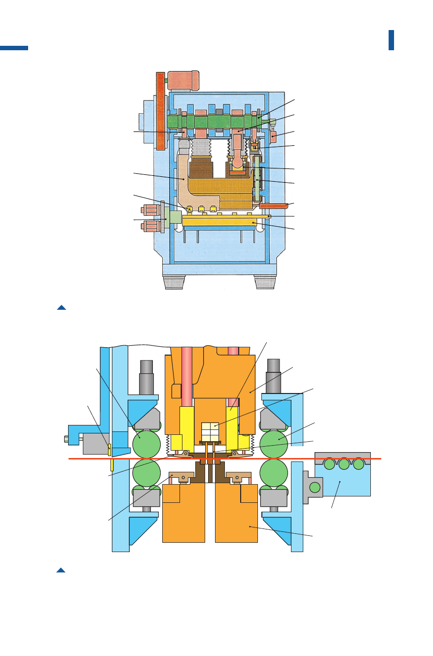
Fig. 4.6.29 Structure of an all-across perforating press
drive shaft
slide connecting rod
camshaft
pressure point
stripper slide
pressure point, slide
column gib
punch control unit
die beams
clamping plate
stripper connecting rod
stripper slide
clamps
gear box
feed drive
Fig. 4.6.30 Section through an all-across perforating press with die holding system and sepa-
rating shear
hydraulic
clamp
bottomdie
hydraulic
clamp
stripper
hydraulic
cropping
shear
outfeed
roller
infeedroller
infeedtable
punchcontrolbeam
movingstripper
pressbed
slide
perforatingpunch
Metal Forming Handbook / Schuler (c) Springer-Verlag Berlin Heidelberg 1998
The stripper plate is raised during the feed movement sufficiently to
ensure that even corrugated coil stock can be transported through the
open die. After perforation, the corrugated sheet metal can be straight-
ened by the stripper plate.
Before an electrohydraulically powered shear, mounted at the outfeed
roller upright, separates the coil into plates, it can be cut using a supple-
mentary slitting or notching device into various widths. The slitting or
notching device is mounted either at the main slide – the more eco-
nomical solution – or fastened at a slide driven separately by the eccen-
tric shaft. In this case, it must be possible to move the separating shear
out of the way. If the device is mounted at the main slide, it must also be
possible to remove the outfeed system to ensure improved accessibility.
When changing dies, the resetting time required can be reduced by
exchanging the slitting or notching device from the press outfeed side.
The perforating dies can be released by means of hydraulic quick-action
clamping devices and removed complete at the side of the press.
Individual or multiple rows of perforating punches in the die can be
moved into place, depending on the specifications of the program,
using a electrohydraulically actuated sliding beam. Even at maximum
317
Shearing lines
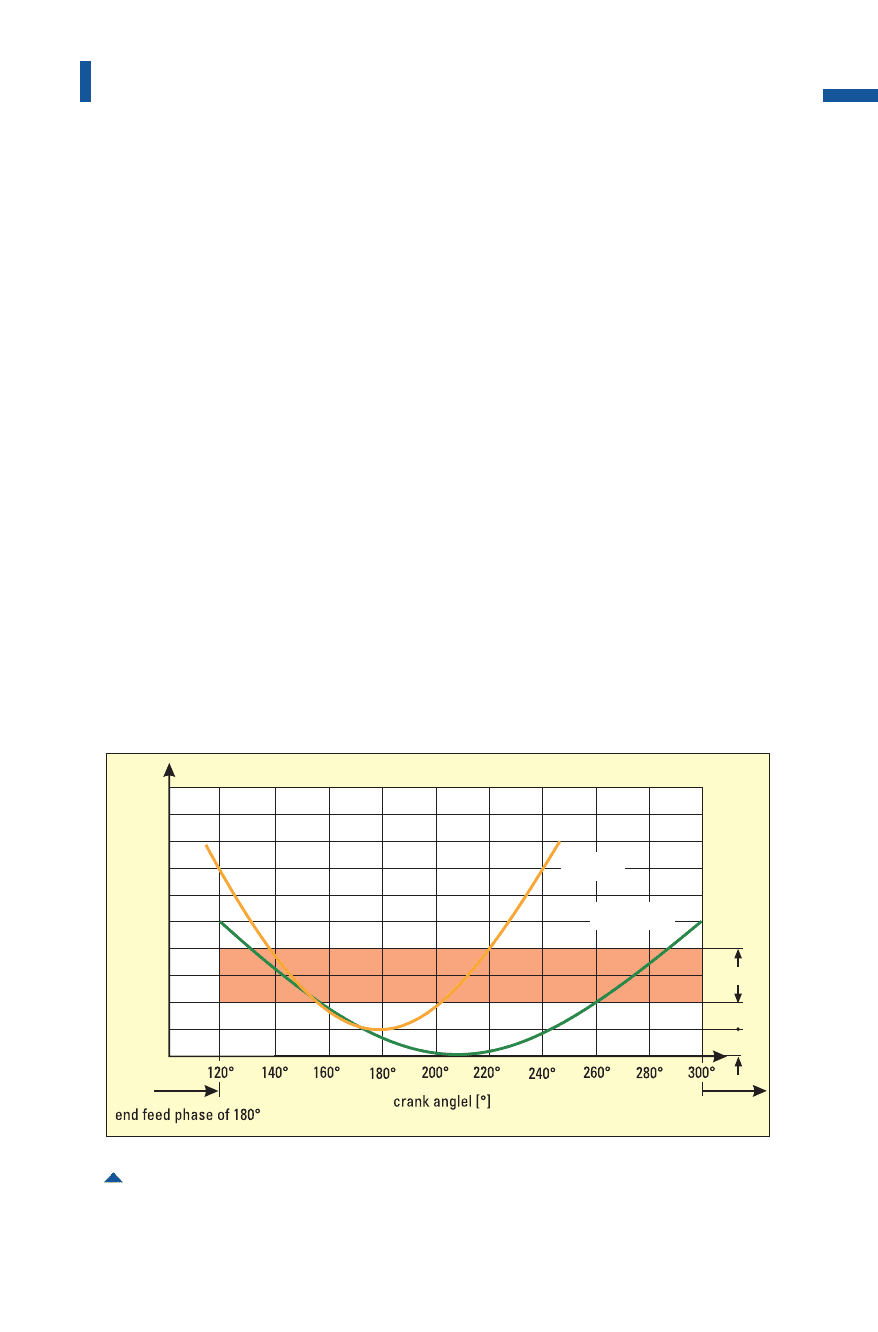
Fig. 4.6.31 Stroking curves of the slide and stripper plate with a sheet metal thickness of 2 mm
slidestroke[mm]
stripper stroke [mm]
start feed phase
0
4
2
2
1
1
6
8
10
120°
slide
stripper
Metal Forming Handbook / Schuler (c) Springer-Verlag Berlin Heidelberg 1998

stroking rates, the control system is able to move the punch in and out
of position without the need to stop the press. The feed devices arranged
directly in front of and behind the tool mounting area can also be pro-
grammed. The upper and lower rollers of the feed units are connected by
means of clearance-free mechanical intermediate gear drives. Both rollers
are supported in several points, and the upper rollers are hydraulically
pressed downward above the support in the area of the rollers. The rollers
are lifted manually or by means of program control. The infeed device is
removable, the outfeed device either removable or stationary.
To ensure a perfectly perforated pattern, a photoelectric camera mon-
itoring system is used (cf.Fig.4.9.7).While the all-across perforating
press is in the set-up mode, the device is programmed using the teach-
in mode. If the actual hole pattern deviates from the programmed pat-
tern during production, the press is automatically switched off.
Strip perforating presses
While perforated sheets are produced in medium and large-series on
all-across perforating presses, strip perforating presses are used for the
production of individual plates, particularly where large or thick sheet
metal materials are used or where individual hole patterns are required
(Fig.4.6.32). Strip perforating presses are available with nominal press
forces ranging from 500 to 2,500kN for sheet metal plates between
1,500 33,000mm and 2,000 36,000 mm with a maximum thickness
of 30 mm. Depending on the sheet metal thickness and feed step, it is
possible to achieve between 40 and 400 strokes per minute.
The strip perforating press control system permits simple program-
ming on screen and storage of complex hole patterns. The stored data
records can be simply accessed if a particular production run has to be
repeated.
The sheet metal plates are fastened on a clamping plate which can be
moved horizontally in two axes. Electrical servo drive systems with
clearance-free intermediate gear drives are used to power the feed sys-
tem. These permit perforation to take place during forward and reverse
movement of the material. As is the case with all-across perforating
presses, here too a separately moved stripper plate with stripping func-
tion can be used (Fig. 4.6.33).
Stationary single punches or small punch assemblies perforate the
sheet metal plates. Where complicated hole patterns are involved, the
318
Sheet metal forming and blanking
Metal Forming Handbook / Schuler (c) Springer-Verlag Berlin Heidelberg 1998
punches can be driven using two additional programmable axes. Par-
ticularly complex geometrical shapes can also be programmed record
by record or using the teach-in mode, whereby the patterns being pro-
grammed can be displayed on screen. Temporary deactivation of the
slide movement irrespective of the clamping plate feed movement can
be used to create optionally interrupted patterns.
319
Shearing lines
Fig. 4.6.32 Examples of hole patterns produced on a strip perforating press
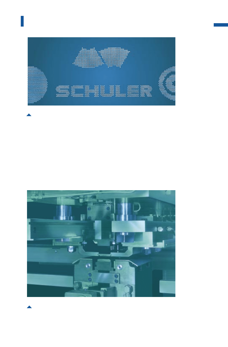
Fig. 4.6.33 Die with separately controlled stripper plate
Metal Forming Handbook / Schuler (c) Springer-Verlag Berlin Heidelberg 1998

The clamping plate is equipped with electrohydraulically actuated
clamping dogs which are retracted in the area of a perforation close to
the material edge, so eliminating the need to reclamp the sheet metal
plate. Support rails equipped with rollers which can be moved as
required on the clamping plate are positioned in front of and behind the
die to prevent unwanted sagging of the sheet metal plate. This system
allows to reduce the mass of inertia to a quarter of that of the old-style
solid construction clamping plates. Used in conjunction with modern
optimized high-performance actuators, extremely short traversing peri-
ods of for example 0.2 s with a feed length of 80 mm can be achieved.
4.6.7Control systems for blanking presses
The concept of production cells and team work is being introduced in
production and assembly plants in order to improve flexibility, quality
and also productivity. This involves extending the responsibility of
each group or single workplace to include planning, inspection and
maintenance activities. As a result, structures will become increasingly
decentralized in the future. The greater degree of automation resulting
from this development will inevitably lead to machines and production
lines of ever greater complexity. At the same time, optimum operating
and maintenance capability as well as high equipment availability must
be achieved. This means that decentralized units must take increasing
responsibility for the provision and updating of production and equip-
ment-related data and information at the point of its generation. A vari-
ety of technical aids must be made available to enable the machine
operator to avoid or quickly remedy any machine standstill.
Information technology
It is necessary to have an operating and information system, integrated in
the machine control, that must fulfil the following criteria (Fig. 4.6.34):
–a simple, easily understood system of operator support when setting
the operating parameters for start-up and resuming operation fol-
lowing a die change or machine failure,
–a tool data management system that has an overview of existing dies
and related features as well as machine parameters and that permits
simple access and editing,
320
Sheet metal forming and blanking
Metal Forming Handbook / Schuler (c) Springer-Verlag Berlin Heidelberg 1998