ALSTOM T&D. Network Protection And Automation Guide (NPAG)
Подождите немного. Документ загружается.

Chapter 12 Distance Protection Schemes
12-7
t 1
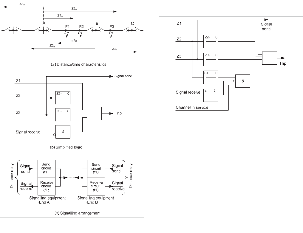
Figure 12.11: Ideal distance protection blocking scheme
The single frequency signalling channel operates both local and
remote receive relays when a block signal is initiated at any
end of the protected section.
12.4.1 Practical Blocking Schemes
A blocking instruction has to be sent by the reverse-looking
relay elements to prevent instantaneous tripping of the remote
relay for Zone 2 faults external to the protected section. To
achieve this, the reverse-looking elements and the signalling
channel must operate faster than the forward-looking
elements. In practice, this is seldom the case and to ensure
discrimination, a short time delay is generally introduced into
the blocking mode trip circuit. Either the Zone 2 or Zone 1
element can be used as the forward-looking element, giving
rise to two variants of the scheme.
12.4.1.1 Blocking over-reaching protection scheme using
Zone 2 element
This scheme (sometimes abbreviated to ‘BLOCKING’ or BOP
Z2) is based on the ideal blocking scheme of Figure 12.11, but
has the signal logic illustrated in Figure 12.12. It is also
known as a ‘directional comparison blocking scheme’ or a
‘blocking over-reach distance protection scheme’
.
t 1
Figure 12.12: Signal logic for BOP Z2 scheme
Operation of the scheme can be understood by considering the
faults shown at F1, F2 and F3 in Figure 12.11 along with the
signal logic of Figure 12.12.
A fault at F1 is seen by the Zone 1 relay elements at both ends
A and B; as a result, the fault is cleared instantaneously at both
ends of the protected line. Signalling is controlled by the Z3
elements looking away from the protected section, so no
transmission takes place, thus giving fast tripping via the
forward-looking Zone 1 elements.
A fault at F2 is seen by the forward-looking Zone 2 elements at
ends A and B and by the Zone 1 elements at end B. No signal
transmission takes place, since the fault is internal and the
fault is cleared in Zone 1 time at end B and after the short time
lag (STL) at end A.
A fault at F3 is seen by the reverse-looking Z3 elements at end
B and the forward looking Zone 2 elements at end A. The
Zone 1 relay elements at end B associated with line section B-
C would normally clear the fault at F3. To prevent the Z2
elements at end A from tripping, the reverse-looking Zone 3
elements at end B send a blocking signal to end A. If the fault
is not cleared instantaneously by the protection on line section
B-C, the trip signal will be given at end B for section A-B after
the Z3 time delay.
The setting of the reverse-looking Zone 3 elements must be
greater than that of the Zone 2 elements at the remote end of
the feeder, otherwise there is the possibility of Zone 2 elements
initiating tripping and the reverse looking Zone 3 elements
failing to see an external fault. This would result in
instantaneous tripping for an external fault. When the
signalling channel is used for a stabilising signal, as in the
above case, transmission takes place over a healthy line
section if power line carrier is used. The signalling channel
should then be more reliable when used in the blocking mode
than in tripping mode.
© 2011 Alstom Grid. Single copies of this document may be filed or printed for personal non-commercial use and must include this
copyright notice but may not be copied or displayed for commercial purposes without the prior written permission of Alstom Grid.
Network Protection & Automation Guide
12-8
It is essential that the operating times of the various relays be
skilfully co-ordinated for all system conditions, so that
sufficient time is always allowed for the receipt of a blocking
signal from the remote end of the feeder. If this is not done
accurately, the scheme may trip for an external fault or
alternatively, the end zone tripping times may be delayed
longer than is necessary.
If the signalling channel fails, the scheme must be arranged to
revert to conventional basic distance protection. Normally, the
blocking mode trip circuit is supervised by a 'channel-in-
service' contact so that the blocking mode trip circuit is
isolated when the channel is out of service, as shown in Figure
12.12.
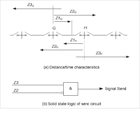
In a practical application, the reverse-looking relay elements
may be set with a forward offset characteristic to provide back-
up protection for busbar faults after the zone time delay. It is
then necessary to stop the blocking signal being sent for
internal faults. This is achieved by making the ‘signal send’
circuit conditional upon non-operation of the forward-looking
Zone 2 elements, as shown in Figure 12.13.
Figure 12.13: Blocking scheme using reverse-looking relays
Blocking schemes, like the permissive over-reach scheme, are
also affected by the current reversal in the healthy feeder due
to a fault in a double circuit line. If current reversal conditions
occur, as described in Section 12.3.2, it may be possible for the
maloperation of a breaker on the healthy line to occur. To
avoid this, the resetting of the ‘signal received’ element
provided in the blocking scheme is time delayed.
The timer with delayed resetting
(t
d
) is set to cover the time
difference between the maximum resetting time of reverse-
looking Zone 3 elements and the signalling channel. So, if
there is a momentary loss of the blocking signal during the
current reversal, the timer does not have time to reset in the
blocking mode trip circuit and no false tripping takes place.
12.4.1.2 Blocking over-reaching protection scheme using
Zone 1 element
This is similar to the BOP Z2 scheme described above, except
that an over-reaching Zone 1 element is used in the logic,
instead of the Zone 2 element. It may also be known as the
BOP Z1 scheme, although it is rarely used.
12.4.2 Weak Infeed Conditions
The protection at the strong infeed terminal will operate for all
internal faults, since a blocking signal is not received from the
weak infeed terminal end. In the case of external faults behind
the weak infeed terminal, the reverse-looking elements at that
end will see the fault current fed from the strong infeed
terminal and operate, initiating a block signal to the remote
end. The relay at the strong infeed end operates correctly
without the need for any additional circuits. The relay at the
weak infeed end cannot operate for internal faults, and so
tripping of that breaker is possible only by means of direct
intertripping from the strong source end.
12.5 DIRECTIONAL COMPARISON
UNBLOCKING SCHEME
The permissive over-reach scheme described in Section 12.3.4
can be arranged to operate on a directional comparison
unblocking principle by providing additional circuitry in the
signalling equipment. In this scheme (also called a ’deblocking
overreach distance protection scheme’), a continuous block (or
guard) signal is transmitted. When the over-reaching distance
elements operate, the frequency of the signal transmitted is
shifted to an 'unblock' (trip) frequency. The receipt of the
unblock frequency signal and the operation of over-reaching
distance elements allow fast tripping to occur for faults within
the protected zone. In principle, the scheme is similar to the
permissive over-reach scheme.
The scheme is made more dependable than the standard
permissive over-reach scheme by providing additional circuits
in the receiver equipment. These allow tripping to take place
for internal faults even if the transmitted unblock signal is
short-circuited by the fault. This is achieved by allowing aided
tripping for a short time interval, typically 100 to 150
milliseconds, after the loss of both the block and the unblock
frequency signals. After this time interval, aided tripping is
permitted only if the unblock frequency signal is received.
This arrangement gives the scheme improved security over a
blocking scheme, since tripping for external faults is possible
only if the fault occurs within the above time interval of
channel failure. Weak Infeed terminal conditions can be
catered for by the techniques detailed in 12.3.5 Weak Infeed
Conditions.
© 2011 Alstom Grid. Single copies of this document may be filed or printed for personal non-commercial use and must include this
copyright notice but may not be copied or displayed for commercial purposes without the prior written permission of Alstom Grid.
Chapter 12 Distance Protection Schemes
12-9
In this way, the scheme has the dependability of a blocking
scheme and the security of a permissive over-reach scheme.
This scheme is generally preferred when power line carrier is
used, except when continuous transmission of signal is not
acceptable.
12.6 COMPARISON OF TRANSFER TRIP AND
BLOCKING RELAYING SCHEMES
On normal two-terminal lines the main deciding factors in the
choice of the type of scheme, apart from the reliability of the
signalling channel previously discussed, are operating speed
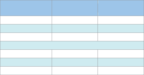
and the method of operation of the system. Table 12.1
compares the important characteristics of the various types of
scheme.
Criterion
Transfer Tripping
Scheme
Blocking Scheme
Speed of operation Fast Not as fast
Speed with in-service testing Slower As fast
Suitable for auto-reclose Yes Yes
Security against maloperation due to:
Current reversal Special features required Special features required
Loss of communications Poor Good
Weak Infeed/Open CB Special features required Special features required
Table 12.1: Comparison of different distance protection schemes
Modern digital or numerical distance relays are provided with a
choice of several schemes in the same relay. Thus scheme
selection is now largely independent of relay selection, and the
user is assured that a relay is available with all the required
features to cope with changing system conditions.
© 2011 Alstom Grid. Single copies of this document may be filed or printed for personal non-commercial use and must include this
copyright notice but may not be copied or displayed for commercial purposes without the prior written permission of Alstom Grid.
© 2011 Alstom Grid. Single copies of this document may be filed or printed for personal non-commercial use and must include this
copyright notice but may not be copied or displayed for commercial purposes without the prior written permission of Alstom Grid.
Alstom Grid 13-1
Chapter 13
Protection of Complex Transmission
Circuits
13.1 Introduction
13.2 Parallel Feeders
13.3 Multi-Ended Feeders – Unit Protection
Schemes
13.4 Multi-Ended Feeders - Distance Relays
13.5 Multi-Ended Feeders – Application of Distance
Protection Schemes
13.6 Protection of Series Compensated Lines
13.7 Example
13.8 References
13.1 INTRODUCTION
Chapters 10-12 have covered the basic principles of protection
for two terminal, single circuit lines whose circuit impedance is
due solely to the conductors used. However parallel
transmission circuits are often installed, either as duplicate
circuits on a common structure, or as separate lines
connecting the same two terminal points via different routes.
Also, circuits may be multi-ended, a three-ended circuit being
the most common.
For economic reasons, transmission and distribution lines can
be much more complicated, maybe having three or more
terminals (multi-ended feeder), or with more than one circuit
carried on a common structure (parallel feeders), as shown in
Figure 13.1. Other possibilities are the use of series capacitors
or direct-connected shunt reactors. The protection of such
lines is more complicated and requires the basic schemes
described in the above chapters to be modified.
The purpose of this chapter is to explain the special
requirements of some of these situations in respect of
protection and identify which protection schemes are
particularly appropriate for use in these situations.
Figure 13.1: Parallel and Multi-ended feeders
13.2 PARALLEL FEEDERS
If two overhead lines are supported on the same structures or
are otherwise in close proximity over part or whole of their
length, there is a mutual coupling between the two circuits.
The positive and negative sequence coupling between the two
circuits is small and is usually neglected. The zero sequence
coupling can be strong and its effect cannot be ignored.
The other situation that requires mutual effects to be taken
into account is when there is an earth fault on a feeder when
© 2011 Alstom Grid. Single copies of this document may be filed or printed for personal non-commercial use and must include this
copyright notice but may not be copied or displayed for commercial purposes without the prior written permission of Alstom Grid.
Network Protection & Automation Guide
13-2
the parallel feeder is out of service and earthed at both ends.
An earth fault in the feeder that is in service can induce current
in the earth loop of the earthed feeder, causing a misleading
mutual compensation signal.
13.2.1 Unit Protection Systems
Types of protection that use current only, for example unit
protection systems, are not affected by the coupling between
the feeders. Therefore, compensation for the effects of mutual
coupling is not required for the relay tripping elements.
If the relay has a distance-to-fault feature, mutual
compensation is required for an accurate measurement. Refer
to Section 13.2.2.3 for how this is achieved.
13.2.2 Distance Protection
There are a number of problems applicable to distance relays,
as described in the following sections.
13.2.2.1 Current Reversal on Double Circuit Lines
When a fault is cleared sequentially on one circuit of a double
circuit line with generation sources at both ends of the circuit,
the current in the healthy line can reverse for a short time.
Unwanted tripping of CBs on the healthy line can then occur if
a Permissive Overreach or Blocking distance scheme (see
Chapter 12) is used. Figure 13.2 shows how the situation can
arise. The CB at
D clears the fault at F faster than the CB at
C. Before CB D opens, the Zone 2 elements at A may see the
fault and operate, sending a permissive trip signal to the relay
for CB
B. The reverse looking element of the relay at CB B
also sees the fault and inhibits tripping of CBs
A and B.
However, once CB
D opens, the relay element at A starts to
reset, while the forward looking elements at
B pick up (due to
current reversal) and could initiate tripping. If the reset time of
the forward-looking elements of the relay at
A is longer than
the operating time of the forward-looking elements at
B, the
relays trip the healthy line. The solution is to incorporate a
blocking time delay that prevents the tripping of the forward-
looking elements of the relays and is initiated by the reverse-
looking element. This time delay must be longer than the reset
time of the relay elements at
A.
Figure 13.2: Fault current distribution in double-circuit line
13.2.2.2 Under-Reach on Parallel Lines
If a fault occurs on a line that lies beyond the remote terminal
end of a parallel line circuit, the distance relay under-reaches
for those zones set to reach into the affected line. Analysis
shows that under these conditions, because the relay sees only
50% (for two parallel circuits) of the total fault current for a
fault in the adjacent line section, the relay sees the impedance
of the affected section as twice the correct value. This may
have to be allowed for in the settings of Zones 2 and 3 of
conventionally set distance relays.
Since the requirement for the minimum reach of Zone 2 is to
the end of the protected line section and the under-reach effect
only occurs for faults in the following line section(s), it is not
usually necessary to adjust Zone 2 impedance settings to
compensate. However, Zone 3 elements are intended to
provide backup protection to adjacent line sections and hence
the under-reaching effect must be allowed for in the
impedance calculations.
13.2.2.3 Behaviour of Distance Relays with Earth Faults
on the Protected Feeder
When an earth fault occurs in the system, the voltage applied
to the earth fault element of the relay in one circuit includes an
induced voltage proportional to the zero sequence current in
the other circuit.
© 2011 Alstom Grid. Single copies of this document may be filed or printed for personal non-commercial use and must include this
copyright notice but may not be copied or displayed for commercial purposes without the prior written permission of Alstom Grid.
Chapter 13 Protection of Complex Transmission Circuits
13-3
cc
,
SSO
ZZ
1
cc cc
,
SSO
ZZ
1
B
I
A
I
L
Z
1
LO
Z
MO
Z
cc
S
Z
1
L
Z
1
L
nZ
1
B
I
1
A
I
1
c
S
Z
1
L
nZ
1
1
I
1
O
I
BO
I
c
SO
Z
MO
nZ
cc
SO
Z
MO
nZ1
A
O
I
Z
LO MO
nZ
LO M O
ZZ
LO MO
nZ Z1
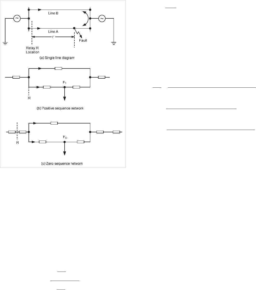
Figure 13.3: General parallel circuit fed from both ends
As the current distribution in the two circuits is unaffected by
the presence of mutual coupling, no similar variation in the
current applied to the relay element takes place and,
consequently, the relay measures the impedance to the fault
incorrectly. Whether the apparent impedance to the fault is
greater or less than the actual impedance depends on the
direction of the current flow in the healthy circuit. For the
common case of two circuits,
A
and
B
, connected at the local
and remote busbars, as shown in Figure 13.3, the impedance
of Line
A
measured by a distance relay, with the normal zero
sequence current compensation from its own feeder, is given
by:
°
°
¿
°
°
¾
½
°
°
¯
°
°
®
¸
¸
¹
·
¨
¨
©
§
¸
¸
¹
·
¨
¨
©
§
K
I
I
M
I
I
nZZ
A
A
A
B
LA
0
1
0
0
1
2
1
Equation 13.1
where:
1
0
L
M
Z
Z
M
The true impedance to the fault is
nZ
L1
where n is the per unit
fault position measured from
R and Z
L1
is the positive
sequence impedance of a single circuit. The 'error' in
measurement is determined from the fraction inside the
bracket; this varies with the positive and zero sequence
currents in circuit
A
and the zero sequence current in circuit
B
.
These currents are expressed below in terms of the line and
source parameters:
00
'
0
''
0
'
0
''
0
0
0
12
1
MLSS
SS
A
B
ZZZnZn
ZnnZ
I
I
1
1
''
1
'
1
1
'
1
''
1
1
2
12
I
ZZZ
ZZnZn
I
LSS
LSS
A
0
00
''
0
'
0
00
'
0
''
0
0
2
12
I
ZZZZ
ZZZnZn
I
MLSS
MLSS
A
and
Z
M0
= zero sequence mutual impedance between two
circuits
NOTE: For earth faults
I
1
= I
0
All symbols in the above expressions are either self-explanatory
from Figure 13.3 or have been introduced in Chapter 11.
Using the above formulae, families of reach curves may be
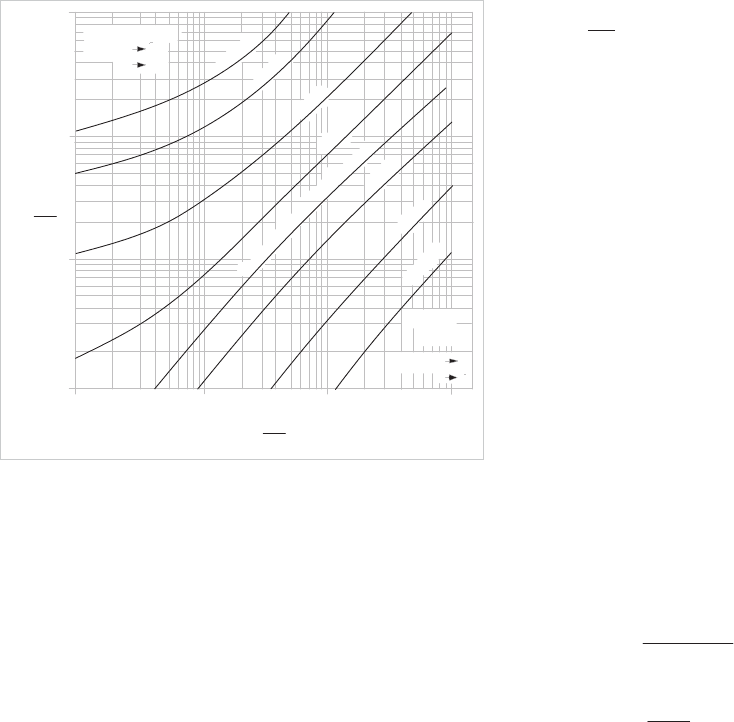
constructed, of which Figure 13.4 is typical. In this figure,
n’
is the effective per unit reach of a relay set to protect 80% of
the line. It has been assumed that an infinite busbar is located
at each line end, that is,
Z’
S1
and Z”
S1
are both zero. A family
of curves of constant
n’ has been plotted for variations in the
source zero sequence impedances
Z’
S0
and Z”
S0
.
© 2011 Alstom Grid. Single copies of this document may be filed or printed for personal non-commercial use and must include this
copyright notice but may not be copied or displayed for commercial purposes without the prior written permission of Alstom Grid.
Network Protection & Automation Guide
13-4
0.1
0.5
1
5
50
100
0.5 1 5 10 50 100
n
'
n'
n
'
=0
.
7
5
=0
.
8
n
'
n
'
=
0
.
9
n
'
=
0
.
9
5
Limit of
n'=1
when y
x
0
N
o
m
i
nal
s
e
tti
ng
(
Z
one 1)
Limit of n' =0.67
when y
x
0
f
f
ªº
«»
¬¼
SO
LO
Z
x
Z
cc
ªº
«»
¬¼
SO
LO
Z
y
Z
10
n
'
n
'
0.1
=0
.
7
=
0
.6
7
5
=
0.
68
=0
.
8
5
Figure 13.4: Typical reach curves showing the effect of mutual
coupling
Figure 13.4 shows that relay R can under-reach or over-reach,
according to the relative values of the zero sequence source to
line impedance ratios; the extreme effective per unit reaches
for the relay are 0.67 and 1. Relay over-reach is not a
problem, as the condition being examined is a fault in the
protected feeder, for which relay operation is desirable. In
Figure 13.4, relay R tends to under-reach whereas the relay at
the opposite line end tends to over-reach. As a result, the
Zone 1 characteristic of the relays at both ends of the feeder
overlap for an earth fault anywhere in the feeder – see Section
13.2.2.5 for more details.
Satisfactory protection can be obtained with a transfer trip,
under-reach type distance scheme. Further, compensation for
the effect of zero sequence mutual impedance is not necessary
unless a distance-to-fault facility is provided. Some
manufacturers compensate for the effect of the mutual
impedance in the distance relay elements, while others may
restrict the application of compensation to the distance-to-
fault function only. The latter is easy to implement in software
for a digital/numerical relay but is impractical in relays using
older technologies. Compensation is achieved by injecting a
proportion of the zero sequence current flowing in the parallel
feeder into the relay. However, some Utilities do not permit
this due to the potential hazards associated with feeding a
relay protecting one circuit from a CT located in a different
circuit.
For the relay to measure the line impedance accurately, the
following condition must be met:
1L
R
R
Z
I
V
For a solid phase to earth fault at the theoretical reach of the
relay, the voltage and current in the faulty phase at the
relaying point are given by:
00002211 MBLALALAA
ZIZIZIZIV
021 AAAA
IIII
Equation 13.2
The voltage and current fed into the relay are given by:
00 BMARAR
AR
IKIKII
VV
Equation 13.3
where:
R
K = the residual compensation factor
M
K
= the mutual compensation factor
Thus:
1
10
L
LL
R
Z
ZZ
K
1
0
L
M
M
Z
Z
K
13.2.2.4 Distance Relay Behaviour with Earth Faults on
the Parallel Feeder
Although distance relays with mutual compensation measure
the correct distance to the fault, they may not operate correctly
if the fault occurs in the adjacent feeder. Davison and Wright
[13.1] have shown that while distance relays without mutual
compensation do not over-reach for faults outside the
protected feeder, the relays may see faults in the adjacent
feeder if mutual compensation is provided. With reference to
Figure 13.3, the amount of over-reach is highest when
f
''
0
''
2
''
1 SSS
ZZZ
.
Under these conditions, faults
occurring in the first 43% of feeder A appear to the distance
relay in feeder B to be in its Zone 1 reach. The solution is to
limit the mutual compensation applied to 150% of the zero
sequence compensation.
13.2.2.5 Distance Relay Behaviour with Single-Circuit
Operation
If only one of the parallel feeders is in service, the protection in
the remaining feeder measures the fault impedance correctly,
© 2011 Alstom Grid. Single copies of this document may be filed or printed for personal non-commercial use and must include this
copyright notice but may not be copied or displayed for commercial purposes without the prior written permission of Alstom Grid.
Chapter 13 Protection of Complex Transmission Circuits
13-5
except when the feeder that is not in service is earthed at both
ends. In this case, the zero sequence impedance network is as
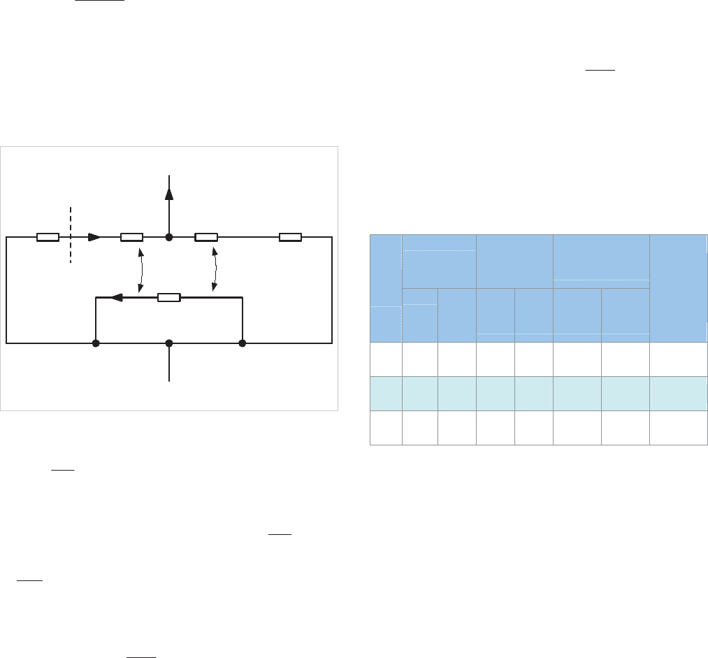
shown in Figure 13.5.
Humpage and Kandil [13.2] have shown that the apparent
impedance presented to the relay under these conditions is
given by:
0
2
00
1
LR
MA
LR
ZI
ZI
ZZ
Equation 13.4
where:
R
I is the current fed into the relay
0ARA
IKI
Relay
Location
LO
nZ
LO
nZ1
c
SO
Z
cc
SO
Z
MO
nZ1
LO
mZ
LO
Z
O
N
HO
I
GO
I
O
I
O
F
Figure 13.5: Zero sequence impedance network during single circuit
operation
The ratio
R
A
I
I
0
varies with the system conditions, reaching a
maximum when the system is earthed behind the relay with
no generation at that end. In this case, the ratio
R
A
I
I
0
is equal
to
0
1
L
L
Z
Z
, and the apparent impedance presented to the relay
is:
¸
¸
¹
·
¨
¨
©
§
2
0
2
0
1
1
L
M
LR
Z
Z
ZZ
It is apparent from the above formulae that the relay has a
tendency to over-reach. Care should be taken when Zone 1
settings are selected for the distance protection of lines in
which this condition may be encountered. To overcome this
possible over-reaching effect, some Utilities reduce the reach
of earth fault relays to around 0.65Z
L1
when lines are taken
out of service for maintenance. However, the probability of
having a fault on the first section of the following line while
one line is out of service is very small, and many Utilities do
not reduce the setting under this condition. It should be noted
that the use of mutual compensation would not overcome the
over-reaching effect since earthing clamps are normally placed
on the line side of the current transformers.
Typical values of zero sequence line impedances for HV lines in
the United Kingdom are given in Table 13.1, where the
maximum per unit over-reach error
2
0
0
¸
¸
¹
·
¨
¨
©
§
L
M
Z
Z
is also given.
The over-reach values quoted in this table are maxima, and
are found only in rare cases. In most cases, there is generation
at both ends of the feeder and the amount of over-reach is
therefore be reduced. In the calculations carried out by
Humpage and Kandil, with more realistic conditions, the
maximum error found in a 400kV double circuit line was
18.6%.
Conductor size
Zero sequence
mutual
impedance ZM0
Zero sequence line
impedance ZL0
Line
volts
(in
2
)
Metric
equiv.
(mm
2
)
Ohms
/mile
Ohms
/km
Ohms
/mile
Ohms
/km
Per unit
over-reach
error
(Z
M0
/Z
L0
)
2
132kV 0.4 258
0.3 +
j0.81
0.19+
j0.5
0.41+j
1.61
0.25+
j1.0
0.264
275kV 2 x 0.4 516
0.18+
j0.69
0.11+
j0.43
0.24+
j1.3
0.15+
j0.81
0.292
400kV 4 x 0.4 1032
0.135+
j0.6
0.80+
j0.37
0.16+
j1.18
0.1+
j0.73
0.2666
Table 13.1: Maximum over-reach errors found during single circuit
working
13.3 MULTI-ENDED FEEDERS – UNIT
PROTECTION SCHEMES
A multi-ended feeder is defined as one having three or more
terminals, with either load or generation, or both, at any
terminal. Those terminals with load only are usually known as
’taps’.
The simplest multi-terminal feeders are three-ended, and are
generally known as tee’d feeders. This is the type most
commonly found in practice.
The protection schemes described previously for the protection
of two-ended feeders can also be used for multi-ended feeders.
However, the problems involved in the application of these
schemes to multi-ended feeders are much more complex and
require special attention.
© 2011 Alstom Grid. Single copies of this document may be filed or printed for personal non-commercial use and must include this
copyright notice but may not be copied or displayed for commercial purposes without the prior written permission of Alstom Grid.
Network Protection & Automation Guide
13-6
The protection schemes that can be used with multi-ended
feeders are unit protection and distance schemes. Each uses
some form of signalling channel, such as fibre-optic cable,
power line carrier or pilot wires. The specific problems that
may be met when applying these protections to multi-ended
feeders are discussed in the following sections.
13.3.1 Balanced Voltage Schemes for Tee’d Circuits
Although pilot wire schemes are uncommon in the protection
of transmission circuits (as per the strict title of this chapter),
they are discussed here for completeness.
The balanced voltage scheme is a modification of the
MHOA04 / H0A4 scheme described in Section 10.7.1. Since
it is necessary to maintain linearity in the balancing circuit,
though not in the sending element, the voltage reference is
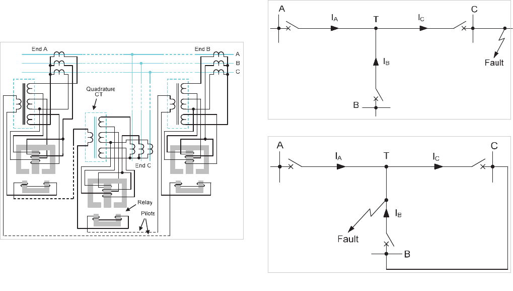
derived from separate quadrature transformers, as shown in
Figure 13.6. These are auxiliary units with summation
windings energised by the main current transformers in series
with the upper electromagnets of the sensing elements. The
secondary windings of the quadrature current transformers at
all ends are interconnected by the pilots in a series circuit that
also includes the lower electromagnets of the relays.
Secondary windings on the relay elements are not used, but
these elements are fitted with bias loops in the usual way.
The plain feeder settings are increased in the tee'd scheme by
50% for one tee and 75% for two.
Figure 13.6: Balanced voltage Tee’d feeder scheme
13.3.2 Power Line Carrier Phase Comparison
Schemes
The operating principle of these protection schemes has
already been covered in detail in Section 10.9. It involves
comparing the phase angles of signals derived from a
combination of the sequence currents at each end of the
feeder. When the phase angle difference exceeds a pre-set
value, the ‘trip angle’, a trip signal is sent to the corresponding
circuit breakers. To prevent incorrect operation for external
faults, two different detectors, set at different levels, are used.
The low-set detector starts the transmission of carrier signal,
while the high-set detector is used to control the trip output.
Without this safeguard, the scheme could operate incorrectly
for external faults because of operating tolerances of the
equipment and the capacitive current of the protected feeder.
This condition is worse with multi-terminal feeders, since the
currents at the feeder terminals can be very dissimilar for an
external fault. In the case of the three-terminal feeder in
Figure 13.7, if incorrect operation is to be avoided, it is
necessary to make certain that the low-set detector at end A or
end B is energised when the current at end C is high enough to
operate the high-set detector at that end. As only one low-set
starter, at end A or end B, needs to be energised for correct
operation, the most unfavourable condition is when currents
I
A
and
I
B
are equal. To maintain stability under this condition,
the high-set to low-set setting ratio of the fault detectors needs
to be twice as large as that required when the scheme is
applied to a plain feeder. This results in a loss of sensitivity,
which may make the equipment unsuitable if the minimum
fault level of the power system is low.
Figure 13.7: External fault conditions
Figure 13.8: Internal fault with current flowing out at one line end
A further unfavourable condition is that shown in Figure 13.8.
If an internal fault occurs near one of the ends of the feeder
(end B in Figure 13.8) and there is little or no generation at
end C, the current at this end may be flowing outwards. The
protection is then prevented from operating, since the fault
© 2011 Alstom Grid. Single copies of this document may be filed or printed for personal non-commercial use and must include this
copyright notice but may not be copied or displayed for commercial purposes without the prior written permission of Alstom Grid.
