ALSTOM T&D. Network Protection And Automation Guide (NPAG)
Подождите немного. Документ загружается.


Chapter 11 Distance Protection
11-21
11.12.2 Residual Compensation
The relays used are calibrated in terms of the positive sequence
impedance of the protected line. Since the zero sequence
impedance of the line between substations ABC and XYZ is
different from the positive sequence impedance, the
impedance seen by the relay in the case of an earth fault,
involving the passage of zero sequence current, will be
different to that seen for a phase fault. Hence, the earth fault
reach of the relay requires zero sequence compensation (see
Section 11.9.2).
For the relay used, this adjustment is provided by the residual
(or neutral) compensation factor
K
ZO
, set equal to:
1
10
3Z
ZZ
K
ZO
1
10
0
3Z
ZZ
K
Z
For each of the transmission lines:
::
D
41.79484.0476.0089.0
1
jZ
L
::
D
87.74632.1576.1426.0
0
jZ
L
Hence,
D
5.6
792.0
0
0
Z
Z
K
K
11.12.3 Zone 1 Phase Reach
The required Zone 1 reach is 80% of the line impedance.
Therefore
,
DD
41.7974.3841.7942.48x8.0
Use
:
D
8074.38 nearest settable value.
11.12.4 Zone 2 Phase Reach
Ideally, the requirements for setting Zone 2 reach are:
x at least 120% of the protected line
x less than the protected line + 50% of the next line
Sometimes, the two requirements are in conflict. In this case,
both requirements can
be met. A setting of the whole of the
line between substations ABC and XYZ, plus 50% of the
adjacent line section to substation PQR is used. Hence, Zone
2 reach:
: ))41.79 (0.484x60x5.0(41.7942.48
DD
:
D
41.7995.62
Use
:
D
8095.62 nearest available setting.
11.12.5 Zone 3 Phase Reach
Zone 3 is set to cover 120% of the sum of the lines between
substations ABC and PQR, provided this does not result in any
transformers at substation XYZ being included. It is assumed
that this constraint is met. Hence, Zone 3 reach:
: ))41.79 (0.484x60x2.1(41.7942.48
DD
:
D
41.79275.83
Use a setting of
:
D
8027.83 , nearest available setting.
11.12.6 Zone Time Delay Settings
Proper co-ordination of the distance relay settings with those
of other relays is required. Independent timers are available for
the three zones to ensure this.
For Zone 1, instantaneous tripping is normal. A time delay is
used only in cases where large d.c. offsets occur and old circuit
breakers, incapable of breaking the instantaneous d.c.
component, are involved.
The Zone 2 element has to grade with the relays protecting the
line between substations XYZ and PQR since the Zone 2
element covers part of these lines. Assuming that this line has
distance, unit or instantaneous high-set overcurrent protection
applied, the time delay required is that to cover the total
clearance time of the downstream relays. To this must be
added the reset time for the Zone 2 element following
clearance of a fault on the adjacent line, and a suitable safety
margin. A typical time delay is 350ms, and the normal range
is 200-500ms.
The considerations for the Zone 3 element are the same as for
the Zone 2 element, except that the downstream fault
clearance time is that for the Zone 2 element of a distance
relay or IDMT overcurrent protection. Assuming distance
relays are used, a typical time is 800ms. In summary:
msT
msT
msT
Z
Z
Z
800
250
0
3
2
1
11.12.7 Phase Fault Resistive Reach Settings
With the use of a quadrilateral characteristic, the resistive
reach settings for each zone can be set independently of the
© 2011 Alstom Grid. Single copies of this document may be filed or printed for personal non-commercial use and must include this
copyright notice but may not be copied or displayed for commercial purposes without the prior written permission of Alstom Grid.
Network Protection & Automation Guide
11-22
impedance reach settings. The resistive reach setting
represents the maximum amount of additional fault resistance
(in excess of the line impedance) for which a zone will trip,
regardless of the fault within the zone.
Two constraints are imposed upon the settings, as follows:
x it must be greater than the maximum expected phase-
phase fault resistance (principally that of the fault arc)
x it must be less than the apparent resistance measured
due to the heaviest load on the line, unless load
blinding (load encroachment) is applied
The minimum fault current at Substation ABC is of the order of
1.8kA,
leading to a typical arc resistance
R
arc
using the van
Warrington formula (Equation 11.4) of 8:. Using the current
transformer ratio as a guide to the maximum expected load
current, the minimum load impedance
Z
lmin
will be 130:.
Typically, the resistive reaches will be set to avoid the
minimum load impedance by a 40% margin for the phase
elements, leading to a maximum resistive reach setting of
78:.
Therefore, the resistive reach setting lies between 8: and
78:. Allowance should be made for the effects of any remote
fault infeed, by using the maximum resistive reach possible.
While each zone can have its own resistive reach setting, for
this simple example they can all be set equal. This need not
always be the case, it depends on the particular distance
protection scheme used and the need to include Power Swing
Blocking.
Suitable settings are chosen to be 80% of the load resistance:
:
:
:
78
78
78
3
2
1
ph
ph
ph
R
R
R
11.12.8 Earth Fault Impedance Reach Settings
By default, the residual compensation factor as calculated in
Section 11.12.2 is used to adjust the phase fault reach setting
in the case of earth faults, and is applied to all zones.
11.12.9 Earth Fault Resistive Reach Settings
The margin for avoiding the minimum load impedance need
only be 20%. Hence the settings are:
:
:
:
104
104
104
3
2
1
G
G
G
R
R
R
This completes the setting of the relay. Table 11.2 also shows
the settings calculated.
11.13 REFERENCE
[11.1] Protective Relays – their Theory and Practice. A.R. van
C. Warrington. Chapman and Hall, 1962
© 2011 Alstom Grid. Single copies of this document may be filed or printed for personal non-commercial use and must include this
copyright notice but may not be copied or displayed for commercial purposes without the prior written permission of Alstom Grid.
Chapter 11 Distance Protection
11-23
© 2011 Alstom Grid. Single copies of this document may be filed or printed for personal non-commercial use and must include this
copyright notice but may not be copied or displayed for commercial purposes without the prior written permission of Alstom Grid.
© 2011 Alstom Grid. Single copies of this document may be filed or printed for personal non-commercial use and must include this
copyright notice but may not be copied or displayed for commercial purposes without the prior written permission of Alstom Grid.
Alstom Grid 12-1
Chapter 12
Distance Protection Schemes
12.1 Introduction
12.2 Zone 1 Extension Scheme (Z1x Scheme)
12.3 Transfer Tripping Schemes
12.4 Blocking Overreaching Schemes
12.5 Directional Comparison Unblocking Scheme
12.6 Comparison of Transfer Trip and Blocking
Relaying Schemes
12.1 INTRODUCTION
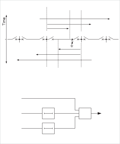
Conventional time-stepped distance protection is illustrated in
Figure 12.1. One of the main disadvantages of this scheme is
that the instantaneous Zone 1 protection at each end of the
protected line cannot be set to cover the whole of the feeder
length and is usually set to about 80%. This leaves two ‘end
zones’, each being about 20% of the protected feeder length.
Faults in these zones are cleared in Zone 1 time by the
protection at one end of the feeder and in Zone 2 time
(typically 0.25 to 0.4 seconds) by the protection at the other
end of the feeder.
Z3
A
Z2
A
Z1
A
A
End Zone
Relay A
Z1
B
Z2
B
Z3
B
Relay B
End Zone
BC
(a) Stepped time/distance characteristics
Z1
Z2
Z3
Trip
(b) Trip logic
Z2
T
0
0Z3
T
0
t 1
F
Figure 12.1: Conventional distance scheme
This situation cannot be tolerated in some applications, for two
main reasons:
x faults remaining on the feeder for Zone 2 time may
cause the system to become unstable
x where high-speed auto-reclosing is used, the non-
simultaneous openin
g of the circuit breakers at both
ends of the faulted section results in no 'dead time'
during the auto-reclose cycle for the fault to be
extinguished and for ionised gases to clear. This results
© 2011 Alstom Grid. Single copies of this document may be filed or printed for personal non-commercial use and must include this
copyright notice but may not be copied or displayed for commercial purposes without the prior written permission of Alstom Grid.
Network Protection & Automation Guide
12-2
in the possibility that a transient fault will cause
permanent lockout of the circuit breakers at each end of
the line section
Even where instability does not occur, the increased duration
of the disturbance may give rise to power quality problems,
and may result in increased plant damage.
Unit schemes of protection that compare the conditions at the
two ends of the feeder simultaneously positively identify
whether the fault is internal or external to the protected section
and provide high-speed protection for the whole feeder length.
This advantage is balanced by the fact that the unit scheme
does not provide the back up protection for adjacent feeders
given by a distance scheme.
The most desirable scheme is obviously a combination of the
best features of both arrangements, that is, instantaneous
tripping over the whole feeder length plus back-up protection
to adjacent feeders. This can be achieved by interconnecting
the distance protection relays at each end of the protected
feeder by a communications channel. Communication
techniques are described in detail in Chapter 8.
The purpose of the communications channel is to transmit
information about the system conditions from one end of the
protected line to the other, including requests to initiate or
prevent tripping of the remote circuit breaker. The former
arrangement is generally known as a 'transfer tripping
scheme' while the latter is generally known as a 'blocking
scheme'. However, the terminology of the various schemes
varies widely, according to local custom and practice.
Z3
A
Z1
A
Z1
B
Z2
B
Z3
B
B
(a) Distance/time characteristics
Trip
(b) Simplified logic
Z2
A
A
Z1ext
A
Z1ext
B
Zone 1ext
Zone 1
Auto-reclose
Reset Zone 1ext
C
&
1
Figure 12.2: Zone 1 extension scheme
12.2 ZONE 1 EXTENSION SCHEME (Z1X
SCHEME)
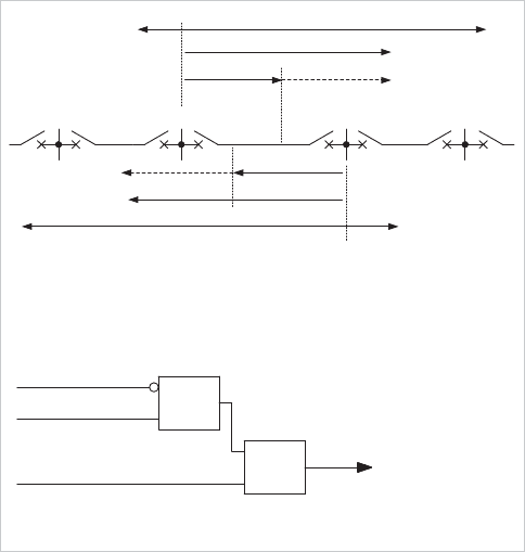
This scheme is intended for use with an auto-reclose facility, or
where no communications channel is available, or the channel
has failed. Thus it may be used on radial distribution feeders,
or on interconnected lines as a fallback when no
communications channel is available, e.g. due to maintenance
or temporary fault. The scheme is shown in Figure 12.2.
The Zone 1 elements of the distance relay have two settings.
One is set to cover 80% of the protected line length as in the
basic distance scheme. The other, known as 'Extended Zone
1’ or ‘Z1X’, is set to overreach the protected line, a setting of
120% of the protected line being common. The Zone 1 reach is
normally controlled by the Z1X setting and is reset to the basic
Zone 1 setting when a command from the auto-reclose relay is
received.
On occurrence of a fault at any point within the Z1X reach, the
relay operates in Zone 1 time, trips the circuit breaker and
initiates auto-reclosure. The Zone 1 reach of the distance relay
is also reset to the basic value of 80%, prior to the auto-reclose
closing pulse being applied to the breaker. This should also
occur when the auto-reclose facility is out of service.
Reversion to the Z1X reach setting occurs only at the end of
the reclaim time. For interconnected lines, the Z1X scheme is
established (automatically or manually) upon loss of the
communications channel by selection of the appropriate relay
setting (setting group in a numerical relay). If the fault is
transient, the tripped circuit breakers will reclose successfully,
but otherwise further tripping during the reclaim time is
subject to the discrimination obtained with normal Zone 1 and
Zone 2 settings.
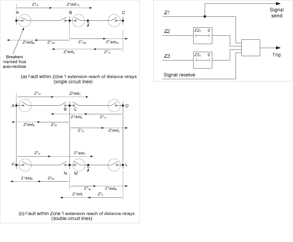
The disadvantage of the Zone 1 extension scheme is that
external faults within the Z1X reach of the relay result in
tripping of circuit breakers external to the faulted section,
increasing the amount of breaker maintenance needed and
needless transient loss of supply to some consumers. This is
illustrated in Figure 12.3(a) for a single circuit line where three
circuit breakers operate and in Figure 12.3(b) for a double
circuit line, where five circuit breakers operate.
© 2011 Alstom Grid. Single copies of this document may be filed or printed for personal non-commercial use and must include this
copyright notice but may not be copied or displayed for commercial purposes without the prior written permission of Alstom Grid.
Chapter 12 Distance Protection Schemes
12-3
Figure 12.3: Performance of Zone 1 extension scheme in conjunction
with auto-reclose relays
12.3 TRANSFER TRIPPING SCHEMES
A number of these schemes are available, as described below.
Selection of an appropriate scheme depends on the
requirements of the system being protected.
12.3.1 Direct Under-reach Transfer Tripping Scheme
The simplest way of reducing the fault clearance time at the
terminal that clears an end zone fault in Zone 2 time is to
adopt a direct transfer trip or intertrip technique, the logic of
which is shown in Figure 12.4. A contact operated by the
Zone 1 relay element is arranged to send a signal to the
remote relay requesting a trip. The scheme may be called a
'direct under-reach transfer tripping scheme’, ‘transfer trip
under-reaching scheme', or ‘intertripping underreach distance
protection scheme’, as the Zone 1 relay elements do not cover
the whole of the line.
t 1
Figure 12.4: Logic for direct underreach transfer tripping scheme
A fault F in the end zone at end
B
in Figure 12.1(a) results in
operation of the Zone 1 relay and tripping of the circuit breaker
at end
B
. A request to trip is also sent to the relay at end
A
.
The receipt of a signal at A initiates tripping immediately
because the receive relay contact is connected directly to the
trip relay. The disadvantage of this scheme is the possibility of
undesired tripping by accidental operation or maloperation of
signalling equipment, or interference on the communications
channel. As a result, it is not commonly used.
12.3.2 Permissive Under-reach Transfer Tripping
(PUP) Scheme
The direct under-reach transfer tripping scheme described
above is made more secure by supervising the received signal
with the operation of the Zone 2 relay element before allowing
an instantaneous trip, as shown in Figure 12.5. The scheme is
then known as a 'permissive under-reach transfer tripping
scheme' (sometimes abbreviated as a PUTT, PUR or PUP Z2
scheme) or ‘permissive underreach distance protection’, as
both relays must detect a fault before the remote end relay is
permitted to trip in Zone 1 time.
© 2011 Alstom Grid. Single copies of this document may be filed or printed for personal non-commercial use and must include this
copyright notice but may not be copied or displayed for commercial purposes without the prior written permission of Alstom Grid.
Network Protection & Automation Guide
12-4
t 1
Figure 12.5: Permissive under-reach transfer tripping scheme
A variant of this scheme, found on some relays, allows tripping
by Zone 3 element operation as well as Zone 2, provided the
fault is in the forward direction. This is sometimes called the
PUP-Fwd scheme.
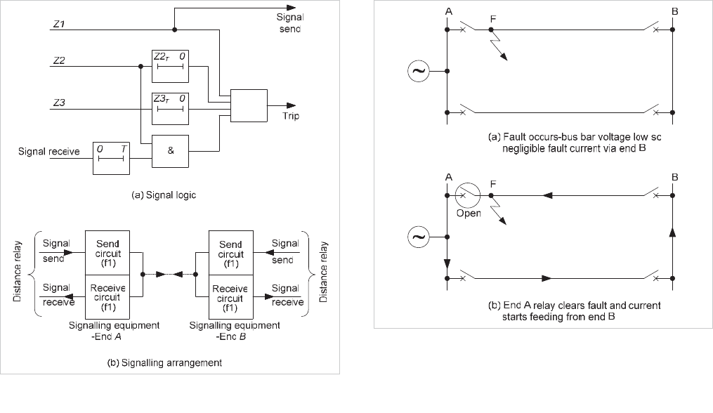
Time delayed resetting of the 'signal received' element is
required to ensure that the relays at both ends of a single-end
fed faulted line of a parallel feeder circuit have time to trip
when the fault is close to one end. Consider a fault F in a
double circuit line, as shown in Figure 12.6. The fault is close
to end A, so there is negligible infeed from end B when the
fault at F occurs. The protection at B detects a Zone 2 fault
only after the breaker at end A has tripped. It is possible for
the Zone 1 element at A to reset, thus removing the permissive
signal to B and causing the 'signal received' element at B to
reset before the Zone 2 unit at end B operates. It is therefore
necessary to delay the resetting of the 'signal received' element
to ensure high speed tripping at end B.
Figure 12.6: PUP scheme: Single-end fed close-up fault on double
circuit line
The PUP schemes require only a single communications
channel for two-way signalling between the line ends, as the
channel is keyed by the under-reaching Zone 1 elements.
When the circuit breaker at one end is open, or there is a weak
infeed such that the relevant relay element does not operate,
instantaneous clearance cannot be achieved for end-zone
faults near the 'breaker open' terminal unless special features
are included, as detailed in Section 12.3.5.
12.3.3 Permissive Under-reaching Acceleration
Scheme
This scheme is applicable only to zone switched distance relays
that share the same measuring elements for both Zone 1 and
Zone 2. In these relays, the reach of the measuring elements
is extended from Zone 1 to Zone 2 by means of a range
change signal immediately, instead of after Zone 2 time. It is
also called an ‘accelerated underreach distance protection
scheme’.
The under-reaching Zone 1 unit is arranged to send a signal to
the remote end of the feeder in addition to tripping the local
circuit breaker. The receive relay contact is arranged to extend
the reach of the measuring element from Zone 1 to Zone 2.
This accelerates the fault clearance at the remote end for faults
that lie in the region between the Zone 1 and Zone 2 reaches.
The scheme is shown in Figure 12.7. Most quality modern
distance relays do not employ switched measuring elements,
so the scheme is likely to fall into disuse.
© 2011 Alstom Grid. Single copies of this document may be filed or printed for personal non-commercial use and must include this
copyright notice but may not be copied or displayed for commercial purposes without the prior written permission of Alstom Grid.

Chapter 12 Distance Protection Schemes
12-5
t 1
t 1
Figure 12.7: Permissive under-reaching acceleration scheme
12.3.4 Permissive Over-reach Transfer Tripping (POP)
Scheme
In this scheme, a distance relay element set to reach beyond
the remote end of the protected line is used to send an
intertripping signal to the remote end. However, it is essential
that the receive relay contact is monitored by a directional
relay contact to ensure that tripping does not take place unless
the fault is within the protected section; see Figure 12.8. The
instantaneous contacts of the Zone 2 unit are arranged to send
the signal, and the received signal, supervised by Zone 2
operation, is used to energise the trip circuit. The scheme is
then known as a 'permissive over-reach transfer tripping
scheme' (sometimes abbreviated to POTT, POR or POP),
'directional comparison scheme', or ‘permissive overreach
distance protection scheme’.
Figure 12.8: Permissive over-reach transfer tripping scheme
Since the signalling channel is keyed by over-reaching Zone 2
elements, the scheme requires duplex communication
channels - one frequency for each direction of signalling.
If distance relays with mho characteristics are used, the
scheme may be more advantageous than the permissive
under-reaching scheme for protecting short lines, because the
resistive coverage of the Zone 2 unit may be greater than that
of Zone 1.
To prevent operation under current reversal conditions in a
parallel feeder circuit, it is necessary to use a current reversal
guard timer to inhibit the tripping of the forward Zone 2
elements. Otherwise maloperation of the scheme may occur
under current reversal conditions, see Section 12.3.2 for more
details. It is necessary only when the Zone 2 reach is set
greater than 150% of the protected line impedance.
The timer is used to block the permissive trip and signal send
circuits as shown in Figure 12.9. The timer is energised if a
signal is received and there is no operation of Zone 2 elements.
An adjustable time delay on pick-up (
t
p
) is usually set to allow
instantaneous tripping to take place for any internal faults,
taking into account a possible slower operation of Zone 2. The
timer will have operated and blocked the ‘permissive trip’ and
‘signal send’ circuits by the time the current reversal takes
place.
© 2011 Alstom Grid. Single copies of this document may be filed or printed for personal non-commercial use and must include this
copyright notice but may not be copied or displayed for commercial purposes without the prior written permission of Alstom Grid.

Network Protection & Automation Guide
12-6
t 1
Figure 12.9: Current reversal guard logic – permissive over-reach
scheme
The timer is de-energised if the Zone 2 elements operate or the
'signal received' element resets. The reset time delay
(t
d
) of
the timer is set to cover any overlap in time caused by Zone 2
elements operating and the signal resetting at the remote end,
when the current in the healthy feeder reverses. Using a timer
in this manner means that no extra time delay is added in the
permissive trip circuit for an internal fault.
The above scheme using Zone 2 relay elements is often
referred to as a POP Z2 scheme. An alternative exists that
uses Zone 1 elements instead of Zone 2, and this is referred to
as the POP Z1 scheme. However POP Z1 is unusual as it
requires Zone 1 to be set overreaching, which is not usual
practice.
12.3.5 Weak Infeed Conditions
In the standard permissive over-reach scheme, as with the
permissive under-reach scheme, instantaneous clearance
cannot be achieved for end-zone faults under weak infeed or
breaker open conditions. To overcome this disadvantage, two
possibilities exist.
The Weak Infeed Echo feature available in some protection
relays allows the remote relay to echo the trip signal back to
the sending relay even if the appropriate remote relay element
has not operated. This caters for conditions of the remote end
having a weak infeed or circuit breaker open condition, so that
the relevant remote relay element does not operate. Fast
clearance for these faults is now obtained at both ends of the
line. The logic is shown in Figure 12.10. A time delay
(T
1
) is
required in the echo circuit to prevent tripping of the remote
end breaker when the local breaker is tripped by the busbar
protection or breaker fail protection associated with other
feeders connected to the busbar. The time delay ensures that
the remote end Zone 2 element will reset by the time the
echoed signal is received at that end.
t1
Figure 12.10: Weak Infeed Echo logic circuit
Signal transmission can take place even after the remote end
breaker has tripped. This gives rise to the possibility of
continuous signal transmission due to lock-up of both signals.
Timer
T
2
is used to prevent this. After this time delay, 'signal
send' is blocked.
A variation on the Weak Infeed Echo feature is to allow
tripping of the remote relay under the circumstances described
above, providing that an undervoltage condition exists, due to
the fault. This is known as the Weak Infeed Trip feature and
ensures that both ends are tripped if the conditions are
satisfied.
12.4 BLOCKING OVERREACHING SCHEMES
The arrangements described so far have used the signalling
channel(s) to transmit a tripping instruction. If the signalling
channel fails or there is no Weak Infeed feature provided, end-
zone faults may take longer to be cleared.
Blocking over-reaching schemes use an over-reaching distance
scheme and inverse logic. Signalling is initiated only for
external faults and signalling transmission takes place over
healthy line sections. Fast fault clearance occurs when no
signal is received and the over-reaching Zone 2 distance
measuring elements looking into the line operate. The
signalling channel is keyed by reverse-looking distance
elements (Z3 in the diagram, though which zone is used
depends on the particular relay, with a dedicated reverse zone
such as Zone 4 now commonly-used in numerical relays). An
ideal blocking scheme is shown in Figure 12.11.
© 2011 Alstom Grid. Single copies of this document may be filed or printed for personal non-commercial use and must include this
copyright notice but may not be copied or displayed for commercial purposes without the prior written permission of Alstom Grid.
