Alciatore D.G., Histand M.B. Introduction to Mechatronics and Measurement Systems
Подождите немного. Документ загружается.

Confirming Pages
11.5 Case Study 2—Mechatronic Design of a Coin Counter 511
When this project was assigned, we had not yet started teaching microcontroller
programming and interfacing in our course. In lieu of this, we had students develop
solutions using basic TTL ICs. Combinational and sequential logic is required to
determine the denomination of the coin and increment the displayed output by a
value corresponding to the denomination. There were as many solutions for this
problem as there were design groups. Figures 11.26 and 11.27 display two student
group solutions for the coin counter processing and display circuit. The outputs were
transmitted to a digital display driver to multiplex the current number of coins and
the accumulated value.
■ CLASS DISCUSSION ITEM 11.2
Coin Counter Circuits
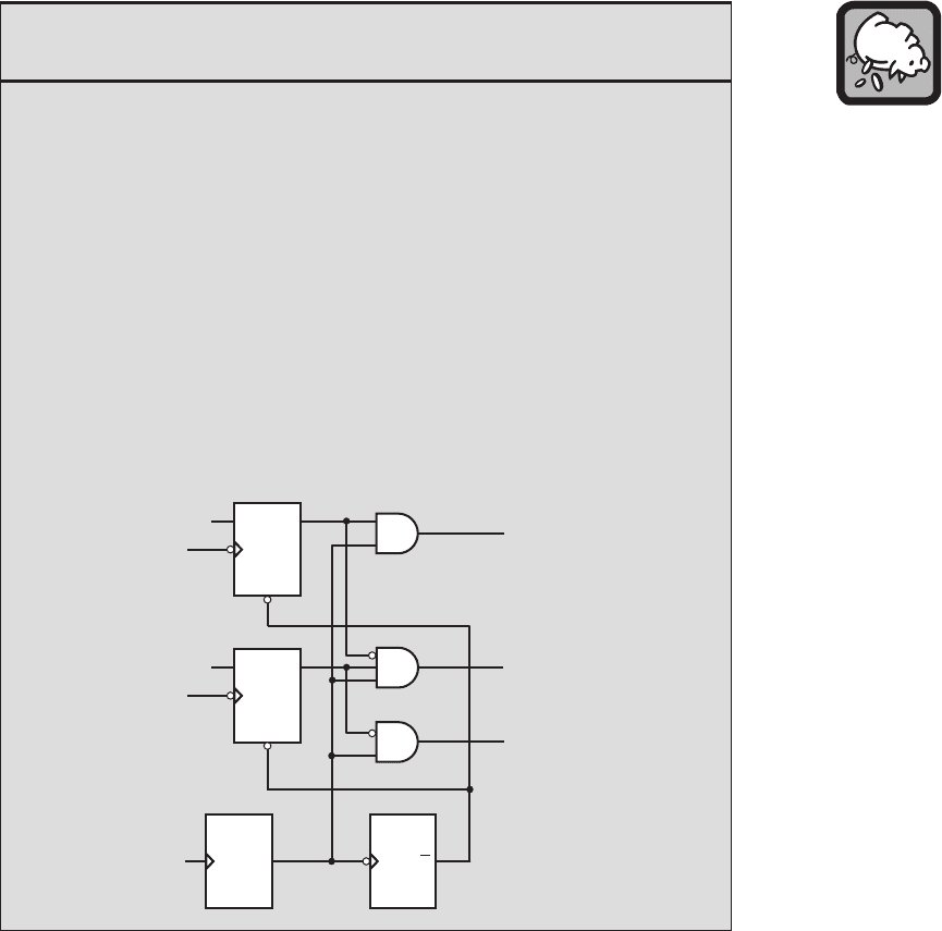
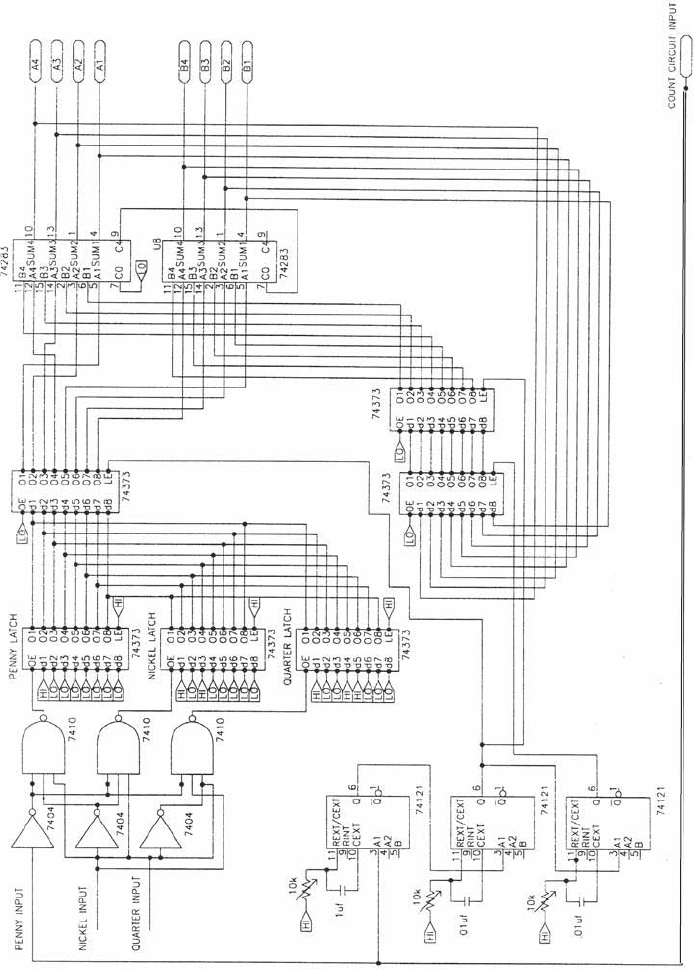
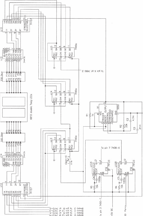
Figure 11.26 shows the coin counter electrical schematic from a student group
report. The design uses one-shots to latch the value corresponding to the coin and
adds that value to the previous sum. There are mistakes in the input portion of the
first half of the circuit used to determine whether the coin is a penny, nickel, or
quarter. The error is in the combinational logic portion of the circuit. Based on the
timing diagrams shown in Figure 11.25 , convince yourself that the logic circuit will
not identify the coin correctly.
Even if the logic were correct, the design could still have problems due to tim-
ing because the one-shot pulse lengths are fixed but the sensor pulse widths depend
on how fast the coin rolls past. A sequential logic circuit that would unequivocally
identify the coin as a penny, nickel, or quarter follows. Draw a timing diagram that
supports the argument that this sequential logic circuit is a robust design. Include
signals S
low
(low sensor), S
middle
(middle sensor), S
high
(high sensor), B, C, L, R, X, Y,
and Z in your diagram. Refer to Figure 11.25 for the phototransistor sensor signal
timing for each type of coin.
C
B
L
R
Y (nickel)
Z (penny)
X (quarter)
S
high
S
middle
S
low
1
DQ
CK
CLR
DQ
QQ
CK
CLR
1
one-shot one-shot
alc80237_ch11_478-522.indd 511alc80237_ch11_478-522.indd 511 10/01/11 8:27 PM10/01/11 8:27 PM
Confirming Pages
Figure 11.26 Counter design 1.
(a) first half of circuit
512 CHAPTER 11 Mechatronic Systems—Control Architectures and Case Studies
alc80237_ch11_478-522.indd 512alc80237_ch11_478-522.indd 512 10/01/11 8:27 PM10/01/11 8:27 PM
Confirming Pages
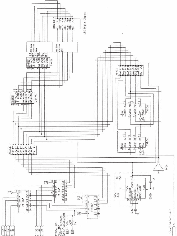
(b) second half of circuit
Figure 11.26 (continued)
11.5 Case Study 2—Mechatronic Design of a Coin Counter 513
alc80237_ch11_478-522.indd 513alc80237_ch11_478-522.indd 513 10/01/11 8:27 PM10/01/11 8:27 PM
Confirming Pages
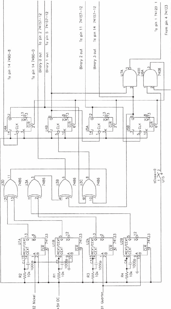
Figure 11.27 Counter design 2.
(a) first half of circuit
514 CHAPTER 11 Mechatronic Systems—Control Architectures and Case Studies
alc80237_ch11_478-522.indd 514alc80237_ch11_478-522.indd 514 10/01/11 8:27 PM10/01/11 8:27 PM
Confirming Pages
(b) second half of circuit
Figure 11.27 (continued )
11.5 Case Study 2—Mechatronic Design of a Coin Counter 515
alc80237_ch11_478-522.indd 515alc80237_ch11_478-522.indd 515 10/01/11 8:27 PM10/01/11 8:27 PM
Confirming Pages
516 CHAPTER 11 Mechatronic Systems—Control Architectures and Case Studies
11.6 CASE STUDY 3—MECHATRONIC
DESIGN OF A ROBOTIC
WALKING MACHINE
In this section, we present a case study of the mechatronic design of an articulated
walking machine. It was executed by undergraduate engineering students in 1994,
following the completion of our introductory mechatronics course for which this
book is used. In 1987, the Society of Automotive Engineers (SAE) began sponsor-
ing an annual Robotic Walking Machine Decathlon, pitting teams from different
universities in a challenge to design articulated walking machines that could execute
10 different performance events including a dash, a slalom, obstacle avoidance, and
crossing a crevasse. Half of the events included walking motion and obstacle avoid-
ance under tether control, that is, control from a human-operated switch box with
an electrical umbilical to the machine. The other half of the events required auton-
omous control via onboard, preprogrammed systems with no human intervention.
Over the years we have seen scores of different walking machine designs, some very
simple and capable of completing just a few events, and others of great sophistica-
tion and creativity capable of completing all events. The excitement and fun of such
competitions is in seeing the fruit of design concepts actually functioning to speci-
fications. Our intent here is not to examine the varieties of walking machines but to
focus on a specific design example to illustrate the mechatronic aspects. We begin
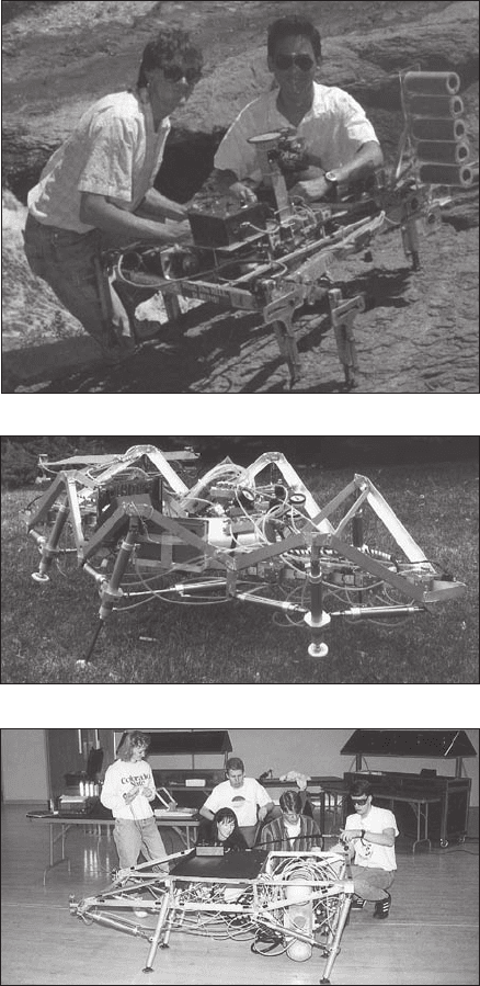
by displaying three different walking machines, all of which won the national SAE
contest (see Figure 11.28 ).
We now present as a case study the design of the 1994 Colorado State walk-
ing machine that the students, applying their ever-present wit, named Airratic. This
design was a refinement of the first pneumatic design from 1992, which was a dra-
matic break from the evolving electromechanical designs of the previous seven years.
With the air-powered designs, the students had to contend with a whole new set of
design constraints: providing an onboard source of stored, pressurized air; control-
ling the mechanical motion of the articulated legs with pneumatic cylinders; distrib-
uting and controlling the air; controlling the pressure; reducing coordinated walking
motion to sets of computer commands; interfacing a computer to the pneumatic con-
trol system; minimizing the weight and size of the machine; ensuring the safety of
the system, including sensors on the machine for obstacle avoidance; and making the
design changeable and adaptable during test trials on the competition floor.
Because the designers elected to power the walking machine pneumatically, an
onboard fiber-wound pressure tank was selected as the energy source for the stra-
tegically placed pneumatic pistons that controlled the position and movements of
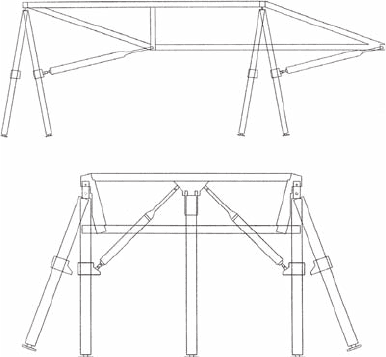
the legs. As shown in Figure 11.29 , the skeletal structure of the walking machine
consisted of welded aluminum members with 16 double-acting pneumatic cylinders.
The four corner legs have 3 degrees of freedom, and the front and rear-center legs
have 2 degrees of freedom. The mechanical design of the six legs was such that
control algorithms could easily produce forward, reverse, sidewise, and diagonal
motion, as well as full-up and full-down motion of the main frame, by simple coor-
dinated control of the 16 cylinders. Each leg included an axial cylinder that could be
alc80237_ch11_478-522.indd 516alc80237_ch11_478-522.indd 516 10/01/11 8:27 PM10/01/11 8:27 PM
Confirming Pages
(b) “Airachnid”—First pneumatic design (1992)
(a) “Lurch”—Scotch yoke mechanism leg design (1989)
Figure 11.28 Student-designed walking machines from Colorado State University.
(c) “Airratic”—Refined pneumatic design (1994)
11.6 Case Study 3—Mechatronic Design of a Robotic Walking Machine 517
extended or retracted. Ten other cylinders were arranged to position the legs in dif-
ferent patterns in the horizontal plane.
For static stability the machine must be supported by a minimum of three legs at
all times, requiring a total of six legs for locomotion. Most walking motions could be
alc80237_ch11_478-522.indd 517alc80237_ch11_478-522.indd 517 10/01/11 8:27 PM10/01/11 8:27 PM
Confirming Pages
Figure 11.29 Aluminum frame and telescoping pneumatic legs.
(a) side view
(b) front view
518 CHAPTER 11 Mechatronic Systems—Control Architectures and Case Studies
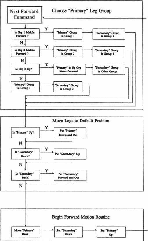
divided into the coordinated movement of two sets of three legs each, called Group
1 Legs and Group 2 Legs. Figure 11.30 displays the flowchart used to develop the
control code for one class of coordinated motion: forward motion of the machine.
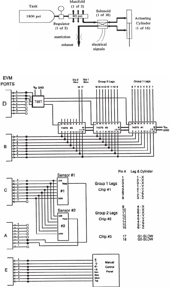
The essence of the control system involves the coordination of 16 pneumatic
cylinders using computer-controlled solenoid valves. Each solenoid valve switches
air from the main cylinder to one side of the pneumatic cylinder and exhausts pres-
surized air from the other side, as shown in Figure 11.31 . Needle valves were manu-
ally adjusted on each solenoid valve to govern cylinder actuating speed.
The complexity of the flowchart in Figure 11.30 warrants a microprocessor-
based solution. This and similar flowcharts for each motion command were very
helpful in designing the computer code necessary to control and coordinate the
motion. The onboard computer controls the solenoid valves via 74373 tristate invert-
ing buffer interface chips receiving signals from an 8-bit port on the computer. As
shown in Figure 11.32 , the 8-bit port is multiplexed to provide 18 bits of information
for coordinated control of the cylinders.
The controller selected was a Motorola 68HC811E2 EVM 8-bit microprocessor-
based single-board computer. It has 128 K of RAM, and 64 K acts as pseudo-ROM
for downloading control programs from an external PC or laptop computer. Thirty
I/O bits are provided and expanded via multiplexing to the 48 bits required for the
control of all of the components of the machine. Computer code was created on a
laptop computer in the high-level language C, then complied and downloaded to the
Motorola EVM for testing. This provided a convenient development environment for
testing and modifying the control strategies.
In addition to various walking motions, the machine included sensor feedback
using two optical retroreflective sensors. The sensors were mounted on a rotating
platform to allow scanning a portion of the region in front of the machine. A digital
alc80237_ch11_478-522.indd 518alc80237_ch11_478-522.indd 518 10/01/11 8:27 PM10/01/11 8:27 PM
Confirming Pages
Figure 11.30 Flowchart for forward motion routine.
11.6 Case Study 3—Mechatronic Design of a Robotic Walking Machine 519
encoder provided position information corresponding to the sense state of the two
sensors. The sensor data was read from the I/O bus of the microprocessor, and soft-
ware control routines used the data to avoid obstacles.
In summary, we examined an example of a student-designed mechatronic sys-
tem that received first place in the 1994 SAE Walking Machine Decathlon. It illus-
trated the use of pneumatic actuators for motion, optical sensors for feedback, and
an onboard microcomputer for controlling the machine in both operator-controlled
alc80237_ch11_478-522.indd 519alc80237_ch11_478-522.indd 519 10/01/11 8:27 PM10/01/11 8:27 PM
Confirming Pages
Figure 11.31 Pneumatic system.
Figure 11.32 Computer ports and I/O board.
520 CHAPTER 11 Mechatronic Systems—Control Architectures and Case Studies
alc80237_ch11_478-522.indd 520alc80237_ch11_478-522.indd 520 10/01/11 8:27 PM10/01/11 8:27 PM