Alciatore D.G., Histand M.B. Introduction to Mechatronics and Measurement Systems
Подождите немного. Документ загружается.


Confirming Pages
Table 11.1 Ziegler-Nichols recommended gains
Controller
K
p
T
i
T
d
P
0.5 K
cr
Infinity 0
PI
0.45 K
cr
P
cr
/1.2
0
PID
0.6 K
cr
P
cr
/2 0.125 P
cr
11.3 Introduction to Control Theory 491
11.3.4 Controller Empirical Design
In cases where it is difficult or impossible to model a system analytically, there
are techniques to empirically design a controller by performing tests on an actual
system. The procedure described in the previous section for simulation is one such
approach, where the gains are adjusted iteratively. There are also software tools
available that can perform system identification automatically, where a model can
be approximated by analyzing the system’s response to various inputs. A control-
ler can then be designed, possibly with the help of other software tools. Video
Demo 8.8 shows a demonstration of how an example set of software tools can be
used to develop a speed controller for a simple DC motor system. Video Demo 8.9
provides much more background and detailed demonstrations of the individual
steps in the process.
A simple empirical method for tuning a PID controller that is sometimes used in
industry is called the Ziegler-Nichols (Z-N) method (see Palm in the bibliography).
The Z-N method is applied by observing the step response of the system under con-
trolled conditions. From the observations, PID gains can then be selected to provide
a fast system response with minimal overshoot and oscillation.
A PID controller expressed in the s domain can be written as
G
controller
s() K
p
K
i
s
-----
K
d
s++=
(11.10)
where K
p
, K
i
, and K
d
are the proportional, integral, and derivative gains. Using the
Ziegler-Nichols method, the controller is usually expressed as
G
controller
s() K
p
(1
1
T
i
s
------- T
d
s)++=
(11.11)
where T
i
is called the reset time and T
d
is the derivative time.
To apply the Z-N method, start by using proportional control action alone
( T
i
⫽ infinity, T
d
⫽ 0) and increase K
p
from zero until the observed output shows
sustained (undamped) oscillation. The resulting period of the oscillations is observed
and labeled P
cr
, and the corresponding gain value is called the critical gain K
cr
. Then
K
p
is reduced by a factor, and K
i
( T
i
) and K
d
( T
d
) are selected based on the propor-
tions in Table 11.1 . Ziegler and Nichols showed that these proportions result in a
good system response for the selected type of controller. Note that K
p
is lower for a
PI controller than a P controller and higher for a PID controller because the I compo-
nent increases the order of the system and may destabilize it, and the D component
tends to stabilize the system, so K
p
can be increased a little.
Video Demo
8.8National
Instruments DC
motor demo
8.9National
Instruments
LabVIEW DC
motor controller
design
alc80237_ch11_478-522.indd 491alc80237_ch11_478-522.indd 491 10/01/11 8:27 PM10/01/11 8:27 PM
Confirming Pages
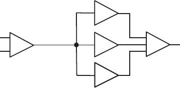
Figure 11.12 Analog PID controller constructed from op amp circuits.
Σ
command
signal
sensor
feedback
error
signal
e(t)
K
d
d/dt
K
i
dt
K
p
+
+
+
+
–
PID controller
output
signal to
physical
plant
Σ
∫
492 CHAPTER 11 Mechatronic Systems—Control Architectures and Case Studies
Often, the Z-N gains will serve only as a starting design, and you may need to
tune the gains (i.e., tweak the K
p
, K
i
, and K
d
parameters) to achieve your desired
design specifications. This usually requires some trial and error.
11.3.5 Controller Implementation
In previous sections, everything was done in simulation, where the physical sys-
tem was represented by a mathematical model. To implement a PID controller in an
actual physical system, the model is replaced by actual hardware, and the controller
must be built as an analog circuit or with a microprocessor-based system running
digital software. In Chapter 5, we learned how to construct proportional gain, inte-
grator, differentiator, summer, and difference circuits using operational amplifiers.
These circuits can serve as the building blocks for an analog controller. Figure 11.12
shows how the various circuits can be combined, in schematic form, to create an ana-
log PID controller. Each control action has a gain ( K
p
, K
i
, or K
d
) created by appropri-
ate choices of component values in the op amp circuits.
An alternative to an op-amp-based analog controller is a digital controller
created with software in a microprocessor-based system (e.g., a microcontroller).
A digital control system is different from an analog controller because it requires a
discrete amount of time to perform control updates. During each update cycle, the
sensor signal is acquired, the controller output is calculated, and the controller signal
is output. The time delay corresponding to the control loop cycle affects the response
of the system. This effect must be accounted for in the mathematical model of the
system to be able to predict system response accurately and to choose control param-
eters intelligently. The concept of the z -transform, where the continuous s -domain
is transformed into a discrete representation, enables us to model and analyze such
systems. Please refer to a book on modern control theory (e.g., Ogata or Palm in the
bibliography at the end of this chapter) if you want to pursue this topic.
To implement a digital controller, the differentiation and integration must be
discretized. If successive error signal samples are referred to as e
1
, e
2
, e
3
, . . ., e
i ⫺ 1
,
e
i
, e
i ⫹ 1
, . . ., we can accumulate an approximation to the integral with the following
equation:
I
i
= I
i–1
+ Δt e
i
(11.12)
alc80237_ch11_478-522.indd 492alc80237_ch11_478-522.indd 492 10/01/11 8:27 PM10/01/11 8:27 PM

Confirming Pages
11.3 Introduction to Control Theory 493
where I
0
⫽ 0 and Δ t is the cycle time of the control loop. The derivative can be
approximated with a finite difference approximation. For example,
D
i
= (e
i
– e
i-1
) / Δt
(11.13)
Although, a digital filter usually needs to be applied to this calculation to minimize
the undesirable effects of high-frequency noise in the position signal (see Class
Discussion Item 11.1). Code for an example control loop cycle might look like the
following:
error_previous ⫽ 0
integral ⫽ 0
loop:
Gosub get_set_point_value ' acquire set_point value
Gosub acquire_sensor_ ' acquire sensor_value
error ⫽ sensor – set_point
integral ⫽ integral ⫹ error * DT
derivative ⫽ (error – error_previous)/DT
output ⫽ KP * error ⫹ KI * integral ⫹ KD * derivative
Gosub send_output_to_system ' update command signal
error_previous ⫽ error
Goto loop
Video Demo
8.8National
Instruments DC
motor demo
8.9National
Instruments
LabVIEW DC
motor controller
design
■ CLASS DISCUSSION ITEM 11.1
Derivative Filtering
As mentioned below Equation 11.13 , derivative calculations often need to be
filtered. One approach to doing this is to average a set of previous derivative calcu-
lations (i.e., use a running average). What is the effect of such an approach, and how
can the example code be modified to achieve this?
11.3.6 Conclusion
This section presented a very brief overview of control theory. Although this topic
cannot really be covered adequately in such a small amount of space, you at least now
have a basic understanding of the main concepts. Anyone interested in pursuing this
topic further needs references (and coursework) completely dedicated to this topic.
There are many software tools available to help with modeling, analysis, and
controller design. Above, we used Matlab and Simulink for simulation and design.
The LabVIEW software introduced in Chapter 8 also provides tools to help with
these tasks. Video Demos 8.8 and 8.9 demonstrate the whole process of model-based
controller design with LabVIEW. Many additional control systems video demonstra-
tions can be found at Internet Link 11.7. Please review some or all of these videos to
help improve your level of understanding of the application of control theory.
Internet Lin
k
11.7Control
system
demonstrations
alc80237_ch11_478-522.indd 493alc80237_ch11_478-522.indd 493 10/01/11 8:27 PM10/01/11 8:27 PM
Confirming Pages
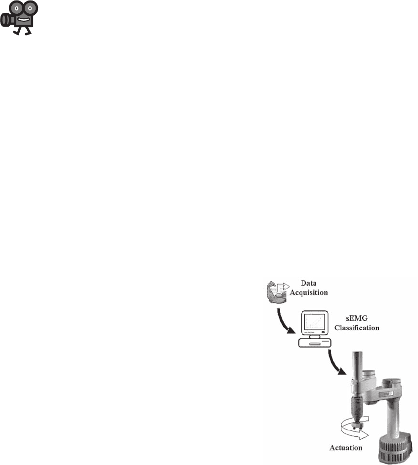
Figure 11.13 Project phases.
■ Data Acquisition— Measuring and
digitizing the myoelectric signal
■ Classification— Estimating the mus-
cle force based on the myoelectric
signal
■ Actuation— Moving a robotic arm
to a position corresponding to the
estimated force
494 CHAPTER 11 Mechatronic Systems—Control Architectures and Case Studies
11.4 CASE STUDY 1—MYOELECTRICALLY
CONTROLLED ROBOTIC ARM
This case study is an extension of Design Example 5.1, which dealt with myo-
genic control of a prosthetic limb. Here, more detail is presented, and the control is
applied instead to a robotic arm. The problem is presented in steps according to the
microcontroller-based system design procedure presented in Section 7.9. This case
study is a good example of how to use PIC microcontrollers to interface to and com-
municate with an assortment of devices including analog circuits, desktop com-
puters, and standard serial interfaces. Video Demo 11.6 demonstrates the finished
product in action. You might want to view the video first so you can better relate to
the information presented below.
1. Define the problem
The goal of this project is to design a system that uses myoelectric voltages from
a person’s biceps as a control signal for a robotic arm. As shown in Figure 11.13 ,
this project can be divided into three phases: data acquisition, classification, and
actuation.
Myoelectric signals, or surface electromyograms ( sEMG ) , are produced dur-
ing muscle contraction when ions flow in and out of muscle cells. When a nerve
sends the signal to initiate muscle contraction, an “action potential” of ions travels
along the length of the muscle. This ionic current can be transduced into electronic
current with Ag-AgCl electrodes placed on the surface of the skin above the con-
tracting muscle. Typically, the greater the contraction level, the higher the measured
amplitude of the sEMG signal. However, even if a contraction level is constant, the
sEMG signal can be quite irregular.
Video Demo
11.6Robot
controlled by an
EMG biosignal
alc80237_ch11_478-522.indd 494alc80237_ch11_478-522.indd 494 10/01/11 8:27 PM10/01/11 8:27 PM
Confirming Pages
11.4 Case Study 1—Myoelectrically Controlled Robotic Arm 495
Research has shown that a typical sEMG signal has the following characteristics:
Amplitude 0–5 mV
Frequency range 0–500 Hz
Dominant frequency range 50–150 Hz
As can be seen, the sEMG signal is very small, in the millivolt range. In fact,
electrical noise on the surface of the skin can be of greater magnitude than the
signal of interest. There are three main frequency ranges in which noise may be
present:
a. 0–10 Hz: low-frequency motion artifacts (e.g., wire sway)
b. 60 Hz: line noise (e.g., electrical equipment in the room)
c. >500 Hz: high-frequency noise (e.g., random movement between the electrodes
relative to the muscle)
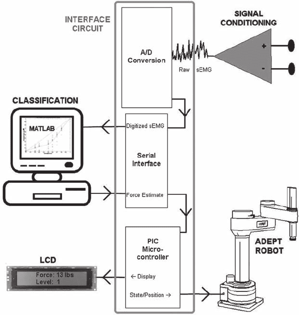
2. Draw a functional diagram
Figure 11.14 shows a block diagram depicting the flow of information between the
system’s required components. Before digitizing the sEMG signal, it must be ampli-
fied to take full advantage of the input range of the A/D converter (see Chapter 8
for more details). However, we cannot simply pass the signal into an op amp; if we
did, the noise would also be amplified, and it would be impossible to distinguish
the sEMG from the noise. Consequently, we need to filter out the noise and amplify
the signal prior to A/D conversion. This stage of data acquisition is called signal
conditioning.
After the signal is amplified and the noise is removed, it is ready for A/D con-
version. The digitized signal is then sent to a PC where the muscle force is estimated
based on analysis of the sEMG data. The estimated force is sent via an interface
circuit to the robotic arm. Then the arm moves to a position that corresponds to the
estimated force. For example, at rest the robotic arm will be at zero degrees; at the
maximum contraction level the robotic arm will be at the maximum angle; and at
intermediate contraction levels the robotic arm will be at corresponding angles in-
between. Although we could build a robotic arm from DC or stepper motors, this
project used an AdeptOne-MV robotic arm. This type of robot is usually used for
industrial purposes (e.g., assembly line work), but it also serves as a good laboratory
model of a prosthetic arm.
3. Identify I/O requirements and 4. Select appropriate
microcontroller models
Although a single microcontroller could probably be used with some creative pro-
gramming, two microcontrollers are used to simplify the problem. One microcon-
troller is dedicated to performing the A/D conversion and sending the digitized
signal to a PC. Another microcontroller serves as the interface between the PC
and the robotic arm. For the A/D microcontroller, the primary constraint is that it
must have an analog input with a sampling rate over 1000 Hz (because the sam-
pling theorem states that we must sample at least two times the highest frequency
alc80237_ch11_478-522.indd 495alc80237_ch11_478-522.indd 495 10/01/11 8:27 PM10/01/11 8:27 PM
Confirming Pages
Figure 11.14 System overview.
496 CHAPTER 11 Mechatronic Systems—Control Architectures and Case Studies
component of the signal, which is 500 Hz after it is filtered). A PIC16F819 was
chosen, although any PIC with A/D capability would meet this criterion. The only
salient difference between PICs with analog inputs is their resolution; some are
8 or 12 bit, but most are 10 bit (such as the 16F819). With a 20 MHz oscillator, the
PIC can sample 10 bit values at about 50 kHz. Clearly, this is well above the 1 kHz
required. However, the limiting factor in this process is not the sampling rate but
the time required to transmit the digitized value to a PC. Because of the convenient
functions provided in PicBasic for serial communication, this was chosen as the
communications protocol. The fastest standard serial baud rate for the PIC is 38400
bits per second. Because each byte of data is limited to 8 bits, each 10 bit value is
split up into 2 bytes (plus start and stop bits for each byte). Thus, each 10 bit value
requires 20 bits of data to be sent (2 start bits ⫹ 2 stop bits ⫹ 2 bytes). Consequently,
the PIC can only send digitized values at 1920 Hz (38,400 bits per sec / 20 bits).
Sending data in a constant stream like this, however, can easily cause the data to
be corrupted on the receiving end. If the clocks of the transmitter and receiver are
slightly out of sync, then the receiver (i.e., the PC) may lose track of where the
alc80237_ch11_478-522.indd 496alc80237_ch11_478-522.indd 496 10/01/11 8:27 PM10/01/11 8:27 PM
Confirming Pages
11.4 Case Study 1—Myoelectrically Controlled Robotic Arm 497
bytes of data start and stop. To obviate this problem, a small delay is incorporated in
PicBasic before sending each value.
Every 100 msec the PC estimates the muscle force based on the previous 100
msec of data. Also, the estimated force is “binned.” For example, an estimated force
between 0 and 5 lb would be assigned to bin 0, an estimated force between 5 and 10 lb
would be assigned to bin 1, and so on. The bin number directly corresponds to a
position of the robotic arm. Every 100 msec, the PC will send two bytes back out
the serial port: the estimated force and the bin number. A PIC16F876 was chosen as
the microcontroller to interface the PC to the robotic arm and to display information
on an LCD. The primary factor considered when choosing a PIC was the number of
I/Os. One input is needed for the serial communication, six I/O are required for the
LCD interface, five outputs are used to interface to the Adept robot, and one output
is for a status LED. Although many PIC models can handle these 13 I/O, the 22 I/O
16F876 is used in case future upgrades are desired.
5. Identify necessary interface circuits
The signal conditioning circuit must amplify the small sEMG signal and filter out
noise prior to digitization. An instrumentation amplifier is used as the primary ampli-
fication component, as well as noise reduction component. As described in Section
5.9, an instrumentation amplifier is essentially a difference amplifier buffered with
op amps at each of its two inputs. The buffering op amps provide high input imped-
ance, which improves the difference amplifier’s ability to reject noise (i.e., it has a
high CMRR). The voltage difference that we will measure is the difference between
two electrodes placed on the biceps. As a muscle action potential travels down the
biceps, the first electrode will become positive relative to the more distal electrode;
conversely, as the action potential continues down the biceps, the second electrode
will then become more positive (which, of course, means the first electrode will be
negative relative to the second). In theory, ambient noise will reach the electrodes
simultaneously and will not be amplified, because the voltage difference between the
two electrodes, due to noise, will be zero.
To further eliminate noise, high-pass and low-pass filters are implemented.
A high-pass filter of 10 Hz is desired to reduce motion artifacts and DC offsets. A low-
pass filter of about 500 Hz is desired to reduce high-frequency noise. A low-pass
filter is important prior to A/D conversion to prevent aliasing. Unfortunately, 60 Hz
line noise is in the middle of the frequency range of the sEMG signal so it would not
be a good idea to employ a notch filter to remove this frequency range. Hopefully,
the instrumentation amplifier will sufficiently reject the line noise.
A 0–5 V input range is used on the A/D converter. To ensure that the sEMG
amplitude is in this range, two more components are incorporated in the signal con-
ditioning circuit: a full wave rectifier and an adjustable gain. The full wave rectifier
approximates the absolute value of the signal. Because the sEMG signal is bipolar
(i.e., it can be both positive and negative), passing it through a full-wave rectifier
will guarantee that the signal is entirely positive. Finally, an adjustable gain is use-
ful to account for differences in electrode size, geometry, and positioning, as well as
differences among individuals—all of which affect the amplitude of the signal. By
alc80237_ch11_478-522.indd 497alc80237_ch11_478-522.indd 497 10/01/11 8:27 PM10/01/11 8:27 PM
Confirming Pages
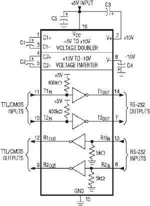
Figure 11.15 MAX232 level converter.
498 CHAPTER 11 Mechatronic Systems—Control Architectures and Case Studies
adjusting the gain of the signal conditioning circuit, we can attain a maximum ampli-
tude of about 5 V (i.e., during maximum contraction levels).
The protocol that dictates how most serial communication is executed is
called RS-232. This protocol states, for example, that a logic 1 is between ⫺ 3 V and
⫺ 25 V, whereas a logic 0 is between ⫹ 3 V and ⫹ 25 V. Because a PIC cannot output
negative voltage (and because some PC serial ports have trouble reading voltages
less than 5 V), it is a good idea to use an RS-232 level converter chip, such as Max-
im’s MAX232 (see Figure 11.15 ). These chips convert TTL/CMOS level signals to
RS-232 level signals, and vice versa. It is also important to note that they also invert
the signal. For example, when given a ⫹ 5 V input, it will output about ⫺ 8 V; when
given 0 V, it will output about ⫹ 8 V. These chips are able to provide these outputs
using a 5 V power supply and ground. This is made possible using a technique called
charge pumping, which uses capacitors to store and boost voltage.
One of the parameters of PicBasic’s Serout command is the mode. Along
with the baud rate, this parameter specifies whether the serial data is driven true
or inverted. Because we are using an RS-232 level converter chip, true is used
because the chip automatically inverts the signal. The MAX232 chip is used to
convert the TTL output of the A/D converter PIC to RS-232 level signals as well
as convert the RS-232 output from the PC to TTL level signals for the robot/LCD
interface.
DB9 serial ports (see Figure 11.16 ) are no longer common on PCs because USB
and other interfaces have made them obsolete; however, one was available on the
computer used for this project. Although the DB9 port has nine pins, only three are
useful for our purpose; the other pins are for handshaking, a method to help regulate
data flow. The only pins necessary for our purposes are listed in Table 11.2. Pin 2 is
alc80237_ch11_478-522.indd 498alc80237_ch11_478-522.indd 498 10/01/11 8:27 PM10/01/11 8:27 PM

Confirming Pages
Figure 11.16 Serial port.
15
69
Table 11.2 Serial port pins
Pin # Description
2 Receive data
3 Transmit data
5 Ground
11.4 Case Study 1—Myoelectrically Controlled Robotic Arm 499
where the PC will receive the digitized sEMG signal, and Pin 3 is where the PC will
send the estimated force and bin number to the interface PIC (in both cases, via the
MAX232 chip).
6. Decide on a programming language
PicBasic Pro is used. Speed and memory constraints are not primary concerns, so
Assembly language is not required. Also, the serial communication and LCD inter-
face commands provided by PicBasic Pro will be quite useful.
7. Draw the schematic
Figure 11.17 shows a circuit diagram for the conditioning circuit. The first stage is
an instrumentation amplifier with a gain of 939 with the resistor values shown. The
next stage is a simple RC filter followed by a buffer op amp. If the buffer op amp
were not included, then the resistance of the following stage would load the filter
(with impedance) and change its behavior. In other words, it would not act as a sim-
ple RC filter. Next is a two-pole Sallen-Key low-pass filter, a type of active filter
(i.e., it exploits the feedback of an op amp). An entire course can be devoted to ana-
log filter design, but suffice it to say that active filters are more robust than passive
filters (such as an RC filter) and that additional “poles” (an RC filter is a single-pole
filter) are better at attenuating unwanted frequencies. The next stage is an inverting
op amp where the feedback resistor is a potentiometer used to adjust the overall gain
of the system. Finally, the last stage is a precision full-wave rectifier, which requires
no forward bias to turn on the diodes.
After the sEMG signal passes through this circuit, it is amplified by about
1000 ⫻ , depending on the potentiometer setting of the inverting amplifier, bandpass
filtered between 8 and 483 Hz, and full-wave rectified. To make this circuit more
robust, the design was prototyped on a custom-made printed circuit board (PCB),
rather than on a breadboard, using PCB123, a free PCB layout program available
online (see Internet Link 11.8). Figure 11.18 show the traces and soldering pads
Internet Lin
k
11.8PCB123
software for
designing custom
printed circuit
boards
alc80237_ch11_478-522.indd 499alc80237_ch11_478-522.indd 499 10/01/11 8:27 PM10/01/11 8:27 PM

Confirming Pages
Figure 11.18 Conditioning circuit PCB layout.
Figure 11.17 Conditioning circuit diagram.
500 CHAPTER 11 Mechatronic Systems—Control Architectures and Case Studies
created with the software for the PCB. Figure 11.19 shows the assembled PCB after
the components are soldered on. Internet Link 11.9 points to a document that illus-
trates all of the steps necessary to create a PCB. See Section 2.10.3 for more infor-
mation about PCBs and soldering.
The only chips used in this example are two TL074s, quad-package JFET op
amps. These op amps will operate over a fairly large range, about ⫾ 5 to ⫾ 18 V. To
make the system portable, two 9 V batteries can be used. Furthermore, a voltage
regulator can be used to produce the ⫹ 5 V necessary to operate the PICs.
Internet Lin
k
11.9Example
of steps in the
printed circuit
board process
alc80237_ch11_478-522.indd 500alc80237_ch11_478-522.indd 500 10/01/11 8:27 PM10/01/11 8:27 PM