Alciatore D.G., Histand M.B. Introduction to Mechatronics and Measurement Systems
Подождите немного. Документ загружается.

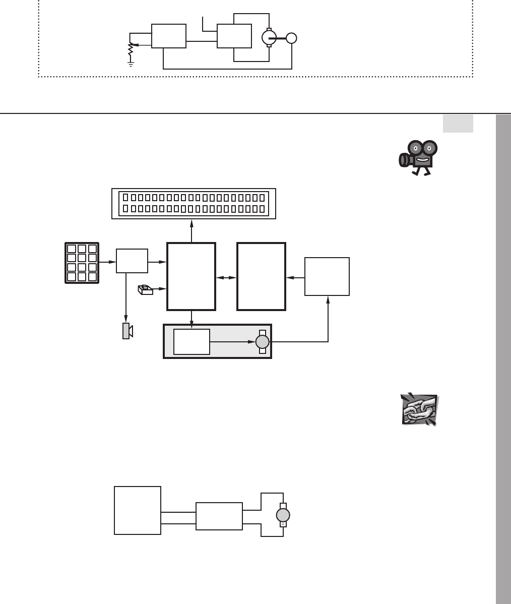
Confirming Pages
(continued )
set point
potentiometer
motor
tachometer
LM3524D
PWM
LMD15200
H-bridge
direction control
THREADED DESIGN EXAMPLE
DC motor position and speed controller—H-bridge driver and PWM speed control C.5
The figure below shows the functional diagram for Threaded Design Example C (see Section 1.3
and Video Demo 1.8), with the portion described here highlighted.
microcontrollers
SLAVE
PIC
MASTER
PIC
liquid crystal display
DC motor with
digital position encoder
quadrature
decoder
and counter
1 2 3
4 5 6
7 8 9
*
0 #
keypad
keypad
decoder
buzzer
H-bridge
driver
button
The complete circuit required for this part of the design is shown below. A commercially
available S17-3A-LV H-bridge was selected because of its ample current capacity and com-
patibility with the selected motor. It also exhibits a near linear relationship between PWM
duty cycle and motor speed over a fairly large range. Details about the H-bridge and motor can
be found at Internet Link 10.4. The two inputs to the H-bridge are a direction line to indicate
whether the motor turns clockwise or counterclockwise, and a PWM line to control the speed
of the motor via an appropriate duty cycle.
PIC16F88
RB7
RB6
12
13
DC motor
S17-3A-LV
H-bridge
+
J2-2
J2-3
J3-1
J3-6
DIR
PWM
VMOTOR
GND
Video Demo
1.8DC motor
position and
speed controller
Internet Lin
k
10.4S17-3A-LV
H-bridge
10.5 DC Motors 451
alc80237_ch10_431-477_sss.indd 451alc80237_ch10_431-477_sss.indd 451 10/01/11 10:24 PM10/01/11 10:24 PM

Confirming Pages
452 CHAPTER 10 Actuators
The code used to rotate the motor at a desired speed is presented below. The subroutine
pwm_ periods calculates the pulse segment widths to create a duty cycle proportional to the
desired motor speed. The subroutine pwm_ pulse is called continuously by run_motor to keep
the motor rotating at the selected speed. The comments in the code explain some of the details
involved with the solution.
' Define I/O pin names
motor_dir Var PORTB.7 ' motor H-bridge direction line
motor_pwm Var PORTB.6 ' motor H-bridge pulse-width-modulation line
' Declare Variables
motor_speed Var BYTE ' motor speed as percentage of maximum (0 to 100)
motion_dir Var BIT ' motor direction (1:CW/Forward 0:CCW/Reverse)
on_time Var WORD ' PWM ON pulse width
off_time Var WORD ' PWM OFF pulse width
pwm_cycles Var BYTE ' # of PWM pulses sent during the position control loop
' Define constants
pwm_period Con 50 ' period of each motor PWM signal cycle (in microsec)
' (50 microsec corresponds to 20kHz)
' Initialize I/O and variables
TRISB.6 0 ' configure H-bridge DIR pin as an output
TRISB.7 0 ' configure H-bridge PWM pin as an output
motion_dir CW ' starting motor direction: CW (forward)
motor_speed 50 ' starting motor speed 50% duty cycle
Low motor_pwm ' make sure the motor is off to begin with
' Subroutine to run the motor at the desired speed and direction until the
' stop button is pressed. The duty cycle of the PWM signal is the
' motor_speed percentage
run_motor:
' Set the motor direction
motor_dir motion_dir
' Output the PWM signal
Gosub pwm_periods ' calculate the on and off pulse widths
While (stop_button 0) ' until the stop button is pressed
Gosub pwm_pulse ' send out a full PWM pulse
Wend
Return
'Subroutine to calculate the PWM on and off pulse widths based on the desired
' motor speed (motor_speed)
pwm_periods:
' Be careful to avoid integer arithmetic and
' WORD overflow [max65535] problems
If (pwm_period >655) Then
on_time pwm_period/100
*
motor_speed
off_time pwm_period/100
*
(100-motor_speed)
(continued )
alc80237_ch10_431-477_sss.indd 452alc80237_ch10_431-477_sss.indd 452 10/01/11 10:24 PM10/01/11 10:24 PM

Confirming Pages
Else
on_time pwm_period
*
motor_speed / 100
off_time pwm_period
*
(100-motor_speed) / 100
Endif
Return
' Subroutine to output a full PWM pulse based on the data from pwm_periods
pwm_pulse:
' Send the ON pulse
High motor_pwm
Pauseus on_time
' Send the OFF pulse
Low motor_pwm
Pauseus off_time
Return
10.6 STEPPER MOTORS
A special type of DC motor, known as a stepper motor, is a permanent magnet or
variable reluctance DC motor that has the following performance characteristics: it
can rotate in both directions, move in precise angular increments, sustain a holding
torque at zero speed, and be controlled with digital circuits. It moves in accurate
angular increments, known as steps, in response to digital pulses sent to an electric
drive circuit. The number and rate of the pulses control the position and speed of the
motor shaft. Generally, stepper motors are manufactured with steps per revolution of
12, 24, 72, 144, 180, and 200, resulting in shaft increments of 30 , 15 , 5 , 2.5 , 2 ,
and 1.8 per step. Special micro-stepping circuitry can be designed to allow many
more steps per revolution, often 10,000 steps/rev or more.
Stepper motors are either bipolar, requiring two power sources or a switchable
polarity power source, or unipolar, requiring only one power source. They are pow-
ered by DC sources and require digital circuitry to produce coil energizing sequences
for rotation of the motor. Feedback is not always required for control, but the use of
an encoder or other position sensor can ensure accuracy when exact position control
is critical. The advantage of operating without feedback (i.e., in open-loop mode) is
that a closed-loop control system is not required. Generally, stepper motors produce
less than 1 hp (746 W) and are therefore used only in low-power position control
applications. Video Demos 9.2 and 10.16 show interesting student project examples
of stepper motor applications.
A commercial stepper motor has a large number of poles that define a large
number of equilibrium positions of the rotor. In the case of a permanent magnet step-
per motor, the stator consists of wound poles, and the rotor poles are permanent mag-
nets. Exciting different stator winding combinations moves and holds the rotor in
different positions. The variable reluctance stepper motor has a ferromagnetic rotor
rather than a permanent magnet rotor. Motion and holding result from the attraction
of stator and rotor poles to positions with minimum magnetic reluctance (magnetic
field resistance) that allow for maximum magnetic flux. A variable reluctance motor
Video Demo
9.2Automated
laboratory rat
exercise machine
with IR sensor and
stepper motor
10.16Multifunction
slot machine
10.6 Stepper Motors 453
alc80237_ch10_431-477_sss.indd 453alc80237_ch10_431-477_sss.indd 453 10/01/11 10:24 PM10/01/11 10:24 PM
Confirming Pages
454 CHAPTER 10 Actuators
has the advantage of a lower rotor inertia and therefore a faster dynamic response.
The permanent magnet stepper motor has the advantage of a small residual holding
torque, called the detent torque, even when the stator is not energized.
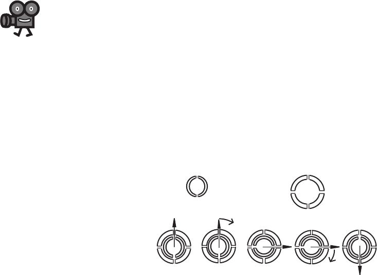
To understand how the rotor moves in an incremental fashion, consider a simple
design consisting of four stator poles and a permanent magnet rotor as illustrated
in Figure 10.21. In step 0, the rotor is in equilibrium, because opposite poles on the
stator and rotor are adjacent to and attract each other. Unless the magnet polarities
of the stator poles are changed, the rotor remains in this position and can withstand
an opposing torque up to a value called the holding torque. When the stator polari-
ties are changed as shown (step 0 to step 1), a torque is applied to the rotor, causing
it to move 90
in the clockwise direction to a new equilibrium position shown as
step 1. When the stator polarities are again changed as shown (step 1 to step 2), the
rotor experiences a torque driving it to step 2. By successively changing the sta-
tor polarities in this manner, the rotor can move to successive equilibrium positions
in the clockwise direction. The sequencing of the pole excitations is the means by
which the direction of rotation occurs. Counterclockwise motion can be achieved by
applying the polarity sequence in the opposite direction. The motor torque is directly
related to the magnetic field strength of the poles and the rotor.
The dynamic response of the rotor and attached load must be carefully consid-
ered in applications that involve starting or stopping quickly, changing or ramping
speeds quickly, or driving large or changing loads. Due to the inertia of the rotor and
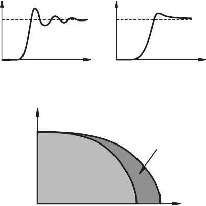
attached load, rotation can exceed the desired number of steps. Also, as illustrated
in Figure 10.22 , a stepper motor driving a typical mechanical system through one
step will exhibit an underdamped response. If damping is increased in the system,
for example, with mechanical, frictional, or viscous damping, the response can be
modified to reduce oscillation, as shown in the figure. Note, however, that even with
an ideal choice for damping, the motor requires time to totally settle into a given
position, and this settling time varies with the step size and the amount of damping.
It is also important to note that the torque required from the motor increases with
added damping. Video Demo 10.17 shows an example of a typical underdamped
second-order system response of a stepper motor with a fairly large step size. It also
shows how the response changes as the step rate increases. Video Demo 10.18 shows
N
NS
S
NN
SS
NN
SS
N
S
step 0 step 1
N
N
S
S
NS
N
S
N
S
N
S
N
N
S
S
step 2
NS
permanent magnet rotor
stator with reversible polarity poles
N or S
N or SN or S
N or S
Figure 10.21 Stepper motor step sequence.
Video Demo
10.17Stepper
motor step response
and acceleration
through resonance
10.18High-speed
video of medium
speed response
alc80237_ch10_431-477_sss.indd 454alc80237_ch10_431-477_sss.indd 454 10/01/11 10:24 PM10/01/11 10:24 PM
Confirming Pages
slow-motion footage of the motor turning at a medium speed to show how the step
response effects are less pronounced at higher step rates.
The torque-speed characteristics for a stepper motor are usually divided into
two regions as illustrated in Figure 10.23 . In the locked step mode, the rotor decel-
erates and may even come to rest between each step. Within this region, the motor
can be instantaneously started, stopped, or reversed without losing step integrity. In
the slewing mode, the speed is too fast to allow instantaneous starting, stopping, or
reversing. The rotor must be gradually accelerated to enter this mode and gradually
decelerated to leave the mode. While in slewing mode, the rotor is in synch with the
stator field rotation and does not settle between steps. The curve between the regions
in the figure indicates the maximum torques that the stepper can provide at different
speeds without slewing. The curve bordering the outside of the slewing mode region
represents the absolute maximum torques the stepper can provide at different speeds.
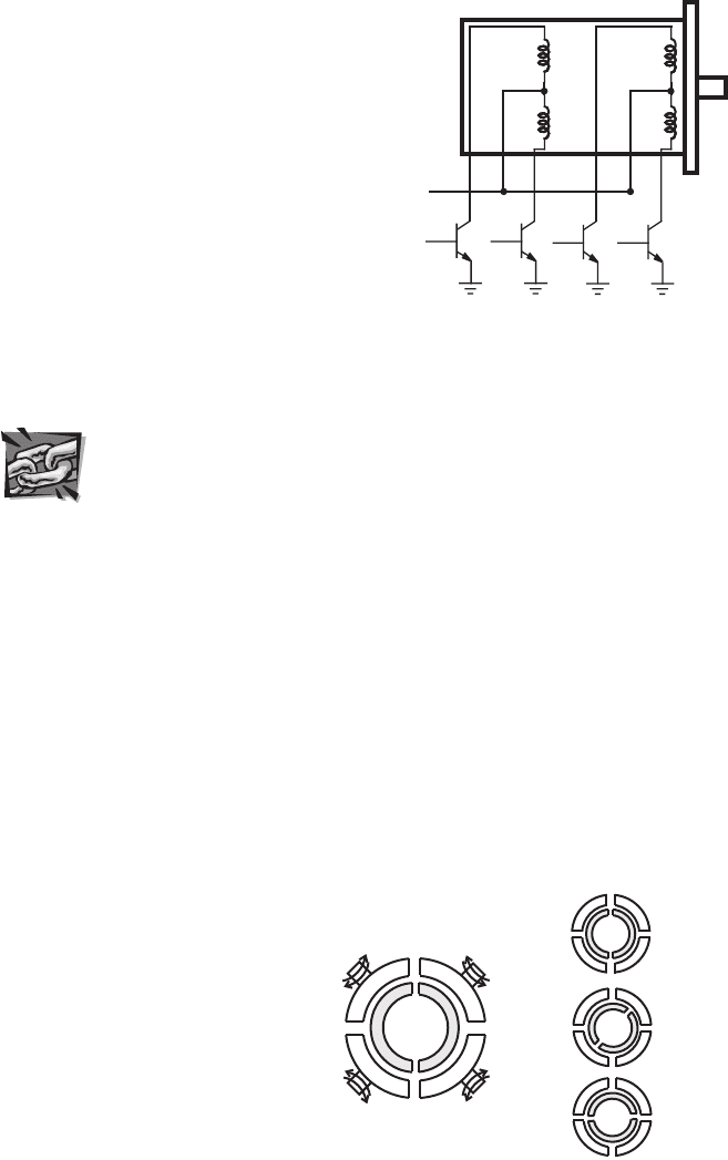
Figure 10.24 illustrates a unipolar stepper motor field coil schematic with exter-
nal power transistors that must be switched on and off to produce the controlled
sequence of stator polarities to cause rotation. The schematic in Figure 10.24 shows
six wires connected to the motor. Because the second and fifth wires are usually
connected externally as shown, manufacturers sometimes connect them inside the
motor, in which case the motor only has five external wires. The wires are usually
color coded by the manufacturers to help the user make a correspondence to the
schematic. Figure 10.24 includes a common color scheme used for a six-wire unipo-
lar stepper motor: yellow (coil 1), red (1/2 common), orange (coil 2), black (coil 3),
green (3/4 common), brown (coil 4). Another common six-wire color scheme is
Figure 10.22 Dynamic response of a single step.
with added damping
rotation
t
t
rotation
step
size
Figure 10.23 Stepper motor torque-speed curves.
torque
speed
locked
step
mode
slewing
mode
10.6 Stepper Motors 455
alc80237_ch10_431-477_sss.indd 455alc80237_ch10_431-477_sss.indd 455 10/01/11 10:24 PM10/01/11 10:24 PM
Confirming Pages
456 CHAPTER 10 Actuators
green (coil 1), white (1/2 common), blue (coil 2), red (coil 3), white (3/4 com-
mon), black (coil 4). A common color scheme for a five-wire unipolar stepper is
red (coil 1), green (coil 2), black (common), brown (coil 3), white (coil 4). If you
come across a motor for which you have no documentation and the color scheme is
unknown, there is a testing procedure you can follow to determine the wire identi-
ties (e.g., see Internet Link 10.5 , being aware that the coils are numbered differently
in the linked Web page. Coils 3-2-1-4 in the Web page correspond to coils 1-2-3-4
or φ
1
-φ
2
- φ
3
- φ
4
here).
Figure 10.25 illustrates the construction of and stepping sequence for a four-
phase unipolar stepper motor. It consists of a two-pole permanent magnet rotor and
a four-pole stator, with each pole wound by two complementary windings (e.g., φ
1
and φ
2
wound in opposite directions on the top left pole). Table 10.1 lists the phase
sequence required to step the motor in full steps, where two of the four phases are
energized (ON) and each stator pole is polarized. Table 10.2 lists the phase sequence
for half-stepping, where between each full step only one phase is energized (ON) and
Figure 10.24 Standard unipolar stepper motor field
coil schematic.
V
s
YEL RED OR
BLK
GRN
BRN
φ
1
φ
2
φ
3
φ
4
Figure 10.25 Example of a unipolar stepper motor.
φ
1
φ
2
φ
2
φ
1
φ
3
φ
4
φ
4
φ
3
stator poles/
windings
step 1
(φ
1
, φ
3
: ON)
step 2
(φ
1
, φ
4
: ON)
step 1.5
(φ
1
: ON)
PM
rotor
N
N
S
S
NS
N
NN
S
SS
S
N
N
S
Internet Lin
k
10.5How to
identify the
different wires of a
stepper motor
alc80237_ch10_431-477_sss.indd 456alc80237_ch10_431-477_sss.indd 456 10/01/11 10:24 PM10/01/11 10:24 PM

Confirming Pages
only two stator poles are polarized. The resolution or number of steps of the motor
is twice as large in the half-step mode (8 steps/rev at 45 ) than in the full-step mode
(4 steps/rev at 90 ), but the holding torque and drive torque change between two
values on alternate cycles in half-step mode. Another technique for increasing the
number of steps is called micro-stepping, where the phase currents are controlled
by fractional amounts, rather than just ON and OFF, resulting in more magnetic
equilibrium positions between the poles. In effect, discretized sine waves are applied
to the phases instead of square waves. The most common commercially available
stepper motors have 200 steps/rev in full-step mode and are sometimes referred to as
1.8 (360 /200) steppers. In micro-stepping mode, 10,000 or more steps per revolu-
tion can be achieved.
Figure 10.26 illustrates a bipolar stepper motor schematic with external power
transistors that must be switched on and off in ordered combinations to produce the
controlled sequence of stator polarities to cause rotation. There are four wires con-
nected to the motor, which easily distinguishes it from a unipolar stepper, which has
either five or six wires. The wires are usually color coded by the manufacturer to
help make a correspondence to the schematic. Figure 10.26 includes a common color
scheme used for a bipolar stepper motor: red ( ) and grey ( ) for the coil A, and
yellow ( ) and black ( ) for coil B.
Table 10.3 lists the phase sequence required to step a bipolar stepper motor in
full steps. Note that the table is the same as for a unipolar stepper (see Table 10.1),
but here sets of two transistors are switched together for each ON or OFF state
Table 10.1 Unipolar full-step phase sequence
Step
1
2
3
4
CW 1 ON OFF ON OFF
↓ 2 ON OFF OFF ON
CCW 3 OFF ON OFF ON
↑ 4 OFF ON ON OFF
Table 10.2
Unipolar half-step phase sequence
Step
1
2
3
4
CW 1 ON OFF ON OFF
↓ 1.5 ON OFF OFF OFF
2 ON OFF OFF ON
2.5 OFF OFF OFF ON
CCW 3 OFF ON OFF ON
↑ 3.5 OFF ON OFF OFF
4 OFF ON ON OFF
4.5 OFF OFF ON OFF
10.6 Stepper Motors 457
alc80237_ch10_431-477_sss.indd 457alc80237_ch10_431-477_sss.indd 457 10/01/11 10:24 PM10/01/11 10:24 PM
Confirming Pages
458 CHAPTER 10 Actuators
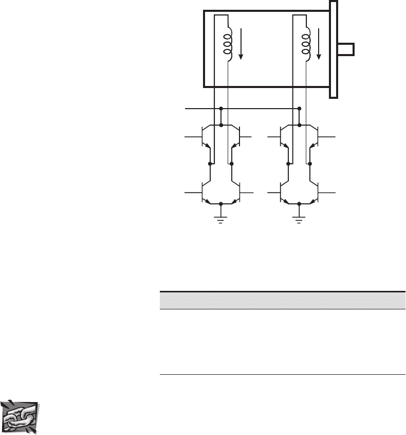
instead of just one with the unipolar sequence. The configuration of transistors is
called an H-bridge configuration (see Design Example 10.1 and Internet Link 10.3
for more information). By switching the transistors in pairs, the current direction can
be reversed. For example, in step 1, transistors 1 and 4 are ON and transistors 2 and 3
are OFF. This applies power to coil A in the forward direction, creating a positive
current (I
A
> 0). Likewise, transistors 5 and 8 are ON and 6 and 7 are OFF in step
1, creating a positive current in coil B (I
B
> 0). In step 2, transistors 5 and 8 are
OFF and 6 and 7 are ON, reversing the direction of the current in coil B (I
B
< 0).
Table 10.4 lists the phase sequence for half-stepping. As with the unipolar motor,
only half of the holding torque is available in the half-step positions, because only
one coil is energized.
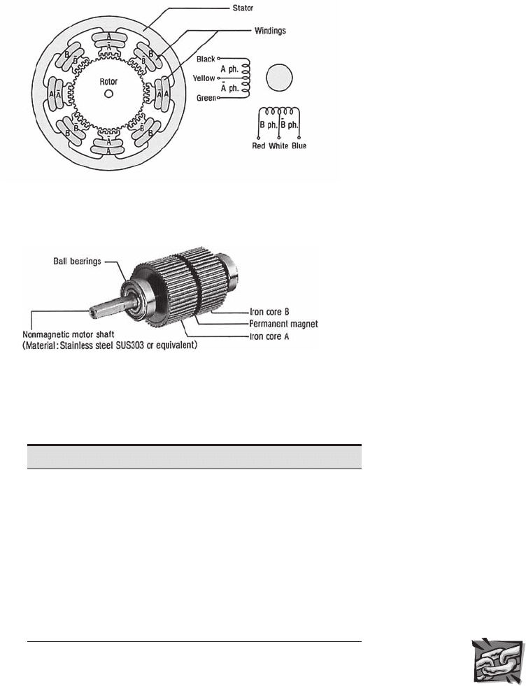
Figure 10.27 illustrates the structure, pole geometry, and coil connections of an
actual stepper motor in more detail. This particular stepper motor can be wired as
Table 10.3 Bipolar full-step phase sequence
Step
1
and
4
2
and
3
5
and
8
6
and
7
CW 1 ON OFF ON OFF
↓ 2 ON OFF OFF ON
CCW 3 OFF ON OFF ON
↑ 4 OFF ON ON OFF
Figure 10.26
Standard bipolar stepper motor field coil schematic.
φ
1
φ
3
φ
2
φ
4
φ
5
φ
7
φ
6
φ
8
RED
GRY
YEL
BLK
I
A
I
B
V
s
Internet Link
10.3H-bridge
resource
alc80237_ch10_431-477_sss.indd 458alc80237_ch10_431-477_sss.indd 458 10/01/11 10:24 PM10/01/11 10:24 PM
Confirming Pages
Internet Lin
k
10.6Stepper
motor online
resource
Table 10.4 Bipolar half-step phase sequence
Step
1
and
4
2
and
3
5
and
8
6
and
7
CW 1 ON OFF ON OFF
↓ 1.5 ON OFF OFF OFF
2 ON OFF OFF ON
2.5 OFF OFF OFF ON
CCW 3 OFF ON OFF OFF
↑ 3.5 OFF ON OFF OFF
4 OFF ON ON OFF
4.5 OFF OFF ON OFF
Figure 10.27
Typical stepper motor rotor and stator configuration.
(Courtesy of Oriental Motor, Torrance, CA)
Figure 10.28 Actual stepper motor rotor. (Courtesy of Oriental
Motor, Torrance, CA)
a four-phase unipolar motor or a two-phase bipolar motor. Figure 10.28 shows the
50-tooth split rotor with one side having north polarity and the other having south
polarity, creating a large number of effective poles.
See Internet Link 10.6 for links to many resources and manufacturers for vari-
ous stepper motor products.
10.6 Stepper Motors 459
alc80237_ch10_431-477_sss.indd 459alc80237_ch10_431-477_sss.indd 459 10/01/11 10:24 PM10/01/11 10:24 PM
Confirming Pages
460 CHAPTER 10 Actuators
10.6.1 Stepper Motor Drive Circuits
A drive circuit for properly phasing the signals applied to the poles of the unipolar
stepper motor for rotation in full-step mode is easily and economically produced
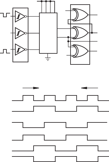
using the components illustrated in Figure 10.29 . A similar drive circuit can be pur-
chased as a single monolithic IC (e.g., E-Lab’s EDE1200, Signetics’ SAA1027, or
Allegro Microsystems’ UCN 5804B). The discrete circuit includes 7414 Schmitt
trigger buffers, a 74191 up-down counter, and 7486 Exclusive OR gates. The Schmitt
triggers (see Section 6.12.2) produce well-defined control signals with sharp rise and
fall times in the presence of noise or fluctuations on the direction (CW/ CCW), ini-
tialization (RESET), and single-step (STEP) inputs. The up-down counter and the
XOR gates in turn create four properly phased motor drive signals. These four digital
signals ( φ
1
, φ
2
, φ
3
, φ
4
) are coupled to the bases of power transistors that sequentially
energize the respective motor coils connected to the DC motor supply, resulting in
shaft rotation. Each square-wave pulse received at the STEP input causes the motor
to rotate a full step in the direction determined by the CW/CCW input.
The timing diagram for the two least significant output bits B
0
and B
1
of the
counter and the phase control signals is shown in Figure 10.30 . Compare the signals
9
7486
CK
DN/UP
74191
RST
CW/CCW
RESET
+5 V
15 101
2
3
+5 V
+5 V
7414
STEP
4
11
5
14
φ
1
φ
2
φ
3
φ
4
B
0
B
1
Figure 10.29 Unipolar stepper motor full-step drive circuit.
Figure 10.30 Timing diagram for full-step unipolar stepper motor
drive circuit.
B
0
B
1
φ
1
φ
2
φ
3
φ
4
CW CCW
alc80237_ch10_431-477_sss.indd 460alc80237_ch10_431-477_sss.indd 460 10/01/11 10:24 PM10/01/11 10:24 PM
