Alciatore D.G., Histand M.B. Introduction to Mechatronics and Measurement Systems
Подождите немного. Документ загружается.

Confirming Pages
■ CLASS DISCUSSION ITEM 10.4
Dissection of Radio Shack Motor
Purchase an inexpensive 1.5–3-V DC motor (e.g., Radio Shack Catalog No.
273-223) and disassemble it. Identify the brushes, the commutator segments, the
armature windings, the laminated rotor poles, and the stator permanent magnets.
Sketch the magnetic field produced by the stator permanent magnets. For different
commutator positions, determine the direction of current flow (and the resulting
field direction) in the armature windings. Determine the direction of torque pro-
duced by the field-field and field-current interactions. Which effect do you think is
stronger in this motor?
Other problems not discussed with these simple models are a back electromo-
tive force (emf) and induction. As the rotor windings cut through the stator magnetic
field, a back emf is induced opposing the voltage applied to the rotor. Also, when
the commutator switches the direction of current, a voltage is induced to oppose the
change in current direction.
The principles of operation of AC motors are similar regarding interaction of
the magnetic fields, but commutation is not required. This is because the magnetic
field rotates around the stator as a result of the AC voltages and the arrangement of
the coils around the stator housing. The rotor windings of asynchronous AC motors
have no external voltage applied; rather, voltages are induced in the rotor windings
due to the rotating fields around the stator. The rotor rotates at slower speeds than
the rotating stator fields (this is called slip ), making the induction possible, hence
the term asynchronous. Because of this action, asynchronous motors are sometimes
referred to as induction machines. With synchronous AC motors, the rotor wind-
ings are energized but through slip rings instead of a commutator. Brushes provide
constant uninterrupted contact with the slip rings, causing fields to rotate around the
rotor windings at the same rate as the fields rotate around the stator. Due to the inter-
action of these fields, the rotor rotates at the same speed as the stator fields, hence
the term synchronous.
Internet Lin
k
10.2Electric
motor illustrations
and animations
Internet Link 10.2 provides excellent illustrations and animations showing the
fundamentals of how various motors, generators, and transformers function.
10.5 DC MOTORS
Direct current (DC) motors are used in a large number of mechatronic designs
because of the torque-speed characteristics achievable with different electrical con-
figurations. DC motor speeds can be smoothly controlled and in most cases are
reversible. Since DC motors have a high ratio of torque to rotor inertia, they can
respond quickly. Also, dynamic braking, where motor-generated energy is fed to a
10.5 DC Motors 441
alc80237_ch10_431-477_sss.indd 441alc80237_ch10_431-477_sss.indd 441 10/01/11 10:24 PM10/01/11 10:24 PM
Confirming Pages
442 CHAPTER 10 Actuators
resistor dissipater, and regenerative braking, where motor-generated energy is fed
back to the DC power supply, can be implemented in applications where quick stops
and high efficiency are desired.
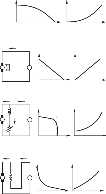
Figure 10.11 illustrates a typical torque-speed curve that displays the torques
a motor can provide at different speeds at rated voltage. For a given torque provided
by the motor, the current-torque curve can be used to determine the amount of
current required when rated voltage is applied. As a general rule of thumb, motors
deliver large torques at low speeds, and large torques imply large motor currents.
The starting torque or stall torque T
s
is the maximum torque the motor can pro-
duce, at zero speed, associated with starting or overloading the motor. The no-load
speed
max
is the maximum sustained speed the motor can attain. This speed can be
reached only when no load or torque is applied to the motor (i.e., only when it is free
running).
Based on how the stator magnetic fields are created, DC motors are classified
into four categories: permanent magnet, shunt wound, series wound, and compound
wound. The electrical schematics, torque-speed curves, and current-torque curves
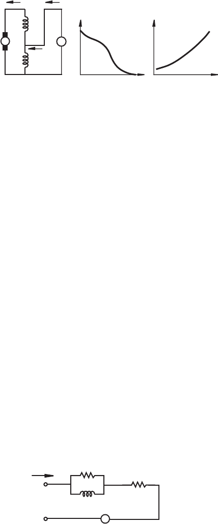
for each configuration are illustrated in Figures 10.12 through 10.15 . In the figures,
V is the DC voltage supply, I
A
is the current in the rotor (armature) windings, I
F
is
the current in the stator (field) windings, and I
L
is the total load current delivered by
the DC supply.
The stator fields in permanent magnet (PM) motors (see Figure 10.12 ) are
provided by permanent magnets, which require no external power source and there-
fore produce no I
2
R heating. A PM motor is lighter and smaller than other, equivalent
DC motors because the field strength of permanent magnets is high. PM motors are
easily reversed by switching the direction of the applied voltage, because the current
and field change direction only in the rotor. The PM motor is ideal in control applica-
tions because of the linearity of its torque-speed relation. The design of a controller
is always easier when the actuator is linear since the system analysis is greatly sim-
plified. When a motor is used in a position or speed control application with sensor
feedback to a controller, it is referred to as a servomotor. PM motors are used only
in low-power applications since their rated power is usually limited to 5 hp (3728 W)
or less, with fractional horsepower ratings being more common. PM DC motors can
be brushed, brushless, or stepper motors.
Shunt motors (see Figure 10.13 ) have armature and field windings connected
in parallel, which are powered by the same supply. The total load current is the sum
of the armature and field currents. Shunt motors exhibit nearly constant speed over
a large range of loading, have starting torques about 1.5 times the rated operating
torque, have the lowest starting torque of any of the DC motors, and can be economi-
cally converted to allow adjustable speed by placing a potentiometer in series with
the field windings.
Series motors (see Figure 10.14 ) have armature and field windings connected
in series so the armature and field currents are equal. Series motors exhibit very
high starting torques, highly variable speed depending on load, and very high speed
when the load is small. In fact, large series motors can fail catastrophically when
they are suddenly unloaded (e.g., in a belt drive application when the belt fails) due
alc80237_ch10_431-477_sss.indd 442alc80237_ch10_431-477_sss.indd 442 10/01/11 10:24 PM10/01/11 10:24 PM
Confirming Pages
Figure 10.11 Motor torque-speed curve.
torque
current
speed
torque
starting
torque (T
s
)
no-load
speed (ω
max
)
Figure 10.12 DC permanent magnet motor schematic and torque-speed curve.
+
V
magnet
I
L
torque
speed
torque
current (I
L
)
Figure 10.13 DC shunt motor schematic and torque-speed curve.
+
I
L
I
A
V
torque
speed
I
F
variable
resistor
small (1–5%)
field current
nearly
constant
torque
current (I
L
)
Figure 10.14 DC series motor schematic and torque-speed curve.
+
heavy
coil
I
A
I
L
V
speed
run-away
torque
speed
torque
current (I
L
)
to dynamic forces at high speeds. This is called run-away. As long as the motor
remains loaded, this poses no problem. The torque-speed curve for a series motor is
hyperbolic in shape, implying an inverse relationship between torque and speed and
nearly constant power over a wide range.
Compound motors (see Figure 10.15 ) include both shunt and series field wind-
ings, resulting in combined characteristics of both shunt and series motors. Part
of the load current passes through both the armature and series windings, and the
remaining load current passes through the shunt windings only. The maximum speed
10.5 DC Motors 443
alc80237_ch10_431-477_sss.indd 443alc80237_ch10_431-477_sss.indd 443 10/01/11 10:24 PM10/01/11 10:24 PM
Confirming Pages
Figure 10.15 DC compound motor schematic and torque-speed curve.
+
I
A
I
F
I
L
V
series
shunt
torque
speed
torque
current (I
L
)
444 CHAPTER 10 Actuators
of a compound motor is limited, unlike a series motor, but its speed regulation is not
as good as with a shunt motor. The torque produced by compound motors is some-
what lower than that of series motors of similar size.
Note that, unlike the permanent magnet motor, when voltage polarity for a
shunt, series, or compound DC motor is changed, the direction of rotation does not
change (i.e., these motors are not reversible). The reason for this is that the polar-
ity of both the stator and rotor changes because the field and armature windings are
excited by the same source.
10.5.1 DC Motor Electrical Equations
As illustrated in Figure 10.16 , the impedance of a DC motor’s armature can be mod-
eled as a resistance R in series with the parallel combination of an inductance L and
a second resistance R
L
. However, as the conducting armature begins to rotate in the
magnetic field produced by the stator, a voltage called the back emf V
emf
is induced
in the armature windings opposing the applied voltage. The back emf is proportional
to the speed of the motor in rad/sec:
V
emf
k
e
ω=
(10.2)
where the proportionality constant k
e
is called the electrical constant of the motor.
R
L
, the equivalent resistive loss in the magnetic circuit, is usually an order of
magnitude larger than R, the resistance of the windings, and can be neglected. If the
voltage applied to the armature is V
in
, the current through the armature is I
in
, and if
we assume R
L
≈ 0, the electrical equation for the motor is
V
in
L
dI
in
dt
--------
RI
in
k
e
ω++=
(10.3)
Figure 10.16 Motor armature equivalent circuit.
R
L
L
R
V
emf
V
in
I
in
+
+
−
alc80237_ch10_431-477_sss.indd 444alc80237_ch10_431-477_sss.indd 444 10/01/11 10:24 PM10/01/11 10:24 PM
Confirming Pages
10.5.2 Permanent Magnet DC Motor Dynamic Equations
Since the permanent magnet DC motor is so important and is the easiest to under-
stand and analyze, we look at its governing equations in more detail. Due to the
interaction between the stator field and the armature current, the torque generated by
a PM DC motor is directly proportional to armature current:
Tk
t
I
in
=
(10.4)
where k
t
is defined as the torque constant of the motor. A PM motor’s electrical
constant k
e
and torque constant k
t
are very important parameters, and they are often
reported in manufacturer specifications. When the dynamics of a motor and its load
are considered, the generated motor torque T is given by
T (J
a
J
L
+ )
d
ω
dt
-------
T
f
T
L
++=
(10.5)
where J
a
and J
L
are the polar moments of inertia of the armature and the attached
load, T
f
is the frictional torque opposing armature rotation (including drag created by
air resistance), and T
L
is the torque dissipated by the load.
When voltage is applied to a PM DC motor, the rotor accelerates until a steady
state operating condition is attained. At steady state, Equation 10.3 becomes
V
in
RI
in
k
e
ω+=
(10.6)
Note that, at steady state, from Equation 10.5 , the motor torque balances the friction
and load torques.
By solving for I
in
in Equation 10.4 and substituting into Equation 10.6 , we get
V
in
R
k
t
---
⎝⎠
⎛⎞
Tk
e
ω+=
(10.7)
and by solving for the motor torque in this equation, we get
T
k
t
R
---
⎝⎠
⎛⎞
V
in
k
e
k
t
R
--------
⎝⎠
⎛⎞
ω–=
(10.8)
This equation predicts the linear torque-speed relation for a PM DC motor with a
fixed applied voltage.
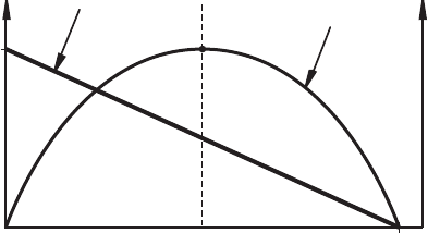
Figure 10.17 shows the linear torque-speed curve and the power-speed curve for
a permanent magnet DC motor with a fixed supply voltage V
in
. The linear relation in
Equation 10.8 can also be expressed in terms of the starting torque T
s
and the no-load
speed
max
as
T(ω) T
s
1
ω
ω
max
---------- -–
⎝⎠
⎛⎞
=
(10.9)
The no-load speed is the steady-state speed at which the motor will run if there is no load
torque ( T
L
0). At this speed, the motor torque balances the friction torque (i.e., T T
f
).
10.5 DC Motors 445
alc80237_ch10_431-477_sss.indd 445alc80237_ch10_431-477_sss.indd 445 10/01/11 10:24 PM10/01/11 10:24 PM
Confirming Pages
Figure 10.17 Permanent magnet DC motor characteristics.
T
s
ω
max
power-speed
curve
ω
*
speed
P
max
power
torque
torque-speed
curve
446 CHAPTER 10 Actuators
By comparing Equations 10.8 and 10.9 , you can see that the stall torque and no-load
speed are related to the motor parameters according to
T
s
k
t
R
---
⎝⎠
⎛⎞
V
in
=
(10.10)
and
ω
max
T
s
R
k
e
k
t
---------
=
( 10.11)
Using Equation 10.9 , the power delivered by the motor at different speeds can
be expressed as
P ω() TωωT
s
1
ω
ω
max
-----------
–
⎝⎠
⎛⎞
==
(10.12)
The maximum power output of the motor occurs at the speed where
dP
dω
-------
T
s
1
2ω
ω
max
-----------
–
⎝⎠
⎛⎞
0==
(10.13)
Solving for the speed gives
ω
*
1
2
-- -
ω
max
=
(10.14)
Therefore, the best speed to run a permanent magnet motor to achieve maximum
power output is half the no-load speed.
In addition to the electrical and torque constants, manufacturers often specify
the armature resistance R. Using Equations 10.4 and 10.10 , the stall current I
s
can
be found in terms of the armature resistance and supply voltage:
I
s
V
in
R
-------
=
(10.15)
alc80237_ch10_431-477_sss.indd 446alc80237_ch10_431-477_sss.indd 446 10/01/11 10:24 PM10/01/11 10:24 PM

Confirming Pages
This equation for current is valid only when the motor rotor is not turning; otherwise,
the rotor current is affected by the back emf induced in the rotor windings. The stall
current is the maximum current through the motor for a given supply voltage.
10.5.3 Electronic Control of a Permanent Magnet DC
Motor
The simplest form of motor control is open loop control, where one simply sets the
drive voltage value, and the motor characteristics and load determine the operat-
ing speed and torque. But most interesting problems require some sort of automatic
control, where the voltage is automatically varied to produce a desired motion. This
is called closed-loop or feedback control, and it requires an output speed and/or
torque sensor to feed back output values to continuously compare the actual output to
a desired value, called the set point. The controller then actively changes the motor
output to move closer to the set point. Electronic speed controllers are of two types:
linear amplifiers and pulse width modulators. Pulse width modulation controllers
have the advantage that they either drive bipolar power transistors rapidly between
cutoff and saturation or they turn FETs on and off. In either case, power dissipation
is small. Servo amplifiers using linear power amplification are satisfactory but pro-
duce a lot of heat, because they function in the transistor linear region. You will find
commercial servo controllers using linear amplifiers, but because of lower power
requirements, ease of design, smaller size, and lower cost, we focus on the switched
amplifier designs, which are generally called pulse-width modulation (PWM)
amplifiers.
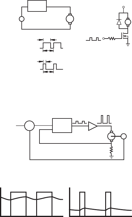
The principle of a PWM amplifier is shown in Figure 10.18 . A DC power supply
voltage is rapidly switched at a fixed frequency f between two values (e.g., ON and
OFF). This frequency is often in excess of 1 kHz. The high value is held during a
variable pulse width t within the fixed period T where
T
1
f
-- -
=
(10.16)
The resulting asymmetric waveform has a duty cycle defined as the ratio between
the ON time and the period of the waveform, usually specified as a percentage:
duty cycle
t
T
---
100%=
(10.17)
As the duty cycle is changed (by the controller), the average current through
the motor changes, causing changes in speed and torque at the output. It is primar-
ily the duty cycle, and not the value of the power supply voltage, that is used to
control the speed of the motor. Video Demo 10.15 explains how PWM signals
are used to control standard radio-controlled (RC) servomotors. Lab Exercise 11
explores how to use a microcontroller to generate a PWM signal to vary the speed
of a DC motor. The end result of the exercise is demonstrated in Video Demo 7.5.
The block diagram of a PWM speed feedback control system for a DC motor
is shown in Figure 10.19 . A voltage tachometer produces an output linearly related
Video Demo
10.15RC servo
with pulse-width-
modulation input
7.5Pulse-width-
modulation speed
control of a DC
motor, with keypad
input
Lab Exercise
Lab 11Pulse-
width-modulation
motor speed
control with a PIC
10.5 DC Motors 447
alc80237_ch10_431-477_sss.indd 447alc80237_ch10_431-477_sss.indd 447 10/01/11 10:24 PM10/01/11 10:24 PM
Confirming Pages
448 CHAPTER 10 Actuators
Figure 10.18 Pulse width modulation of a DC motor.
DC power
supply
(V
s
)
+
PWM
electronics
motor
example drive circuit
faster
(large t)
slower
(small t)
T
t
t
pulses
pulses:
T
V
s
Figure 10.19 PWM velocity feedback control.
motor
power
amp
tachometer
measured speed
set point
(desired)
speed
Σ
−
+
error signal =
set point –
measured speed
PWM
regulator
electronics
Figure 10.20 PWM voltage and motor current.
PWM
voltage
motor
current
high duty cycle
low duty cycle
to the motor speed. This is compared to the desired speed set point (another voltage
that can be manually set or computer controlled). The error and the motor current
are sensed by a pulse-width-modulation regulator that produces a width-modulated
square wave as an output. This signal is amplified to a level appropriate to drive the
motor.
In a PWM motor controller, the armature voltage switches rapidly, and the cur-
rent through the motor is affected by the motor inductance and resistance. Since the
switching speed is high, the resulting current through the motor has a small fluctua-
tion around an average value, as illustrated in Figure 10.20 . As the duty cycle grows
larger, the average current grows larger and the motor speed increases.
alc80237_ch10_431-477_sss.indd 448alc80237_ch10_431-477_sss.indd 448 10/01/11 10:24 PM10/01/11 10:24 PM
Confirming Pages
Although it is possible to design and build a drive circuit for a servomotor with discrete con-
trol and power components, several integrated circuit designs are available that save enor-
mously on time and money in mechatronic design. Consider the very ordinary problem of
controlling a DC motor. Your ultimate intent may be to control speed, direction of rotation,
angle, and/or torque.
To control the speed of a DC motor, we must be able to change the current supplied to
the motor. To control the direction of rotation, the direction of current supplied to the motor
must be reversible. This requires a current amplifier and some means to switch the current
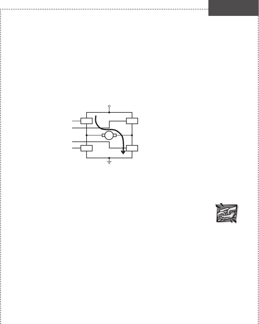
direction. The concept of an H-bridge meets these requirements. It uses four switches
(relays or transistors) arranged in an H configuration around the DC motor (see the fol-
lowing figure). The switches are turned on one pair at a time for the desired direction of
motion.
+V
Q
1
Q
1
Q
2
Q
2
Q
3
Q
3
Q
4
Q
4
If switches Q
1
and Q
3
are on and Q
2
and Q
4
are off, current flows through the motor in
the direction shown and the motor rotates in one direction. Alternatively, if switches Q
2
and
Q
4
are on and Q
1
and Q
3
are off, the motor rotates in the other direction.
An H-bridge can be constructed easily with relays (four SPSTs or two DPDTs); how-
ever, relays cannot be switched very fast, so this limits our PWM options. Also, because
relays are mechanical devices, they can wear out and fail after many switching cycles.
However, for applications where you need only reversibility and not PWM speed control,
relays can be a good option. For applications where we want PWM speed control, tran-
sistors or solid-state relays are better choices. An excellent resource for information and
advice on how to build H-bridges using a variety of components can be found at Internet
Link 10.3.
One can also build a discrete H-bridge with power BJTs or MOSFETs, but it may be
difficult to properly choose and bias the transistors. Therefore, we utilize a monolithic solu-
tion using National Semiconductor’s line of motion control ICs, which can be conveniently
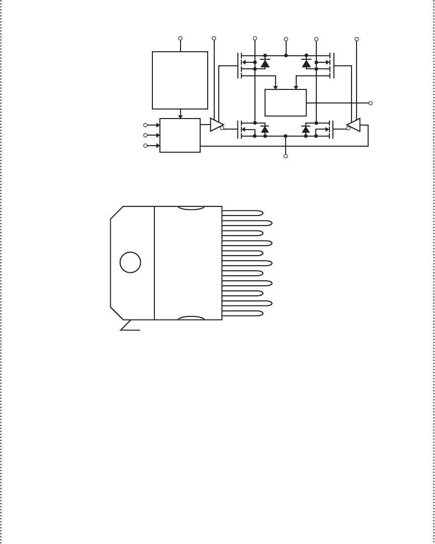
adapted for driving DC motors. Consider the LMD15200, a 3 A, 55 V H-bridge specifically
designed to drive DC and stepper motors. It allows for current direction control, and also
offers features for overcurrent and overtemperature detection, pulse width modulation, and
dynamic braking. The functional diagram follows.
H-Bridge Drive for a DC Motor
(continued )
DESIGN
EXAMPLE 10.1
Internet Lin
k
10.3H-bridge
resource
10.5 DC Motors 449
alc80237_ch10_431-477_sss.indd 449alc80237_ch10_431-477_sss.indd 449 10/01/11 10:24 PM10/01/11 10:24 PM
Confirming Pages
450 CHAPTER 10 Actuators
This design uses power MOSFETs with flyback protection diodes that suppress large
reverse transients across the transistors. The motor poles are connected between Output 1
and Output 2. The voltage supply can be up to 55 V. External digital signals control direc-
tion, braking, and pulse width modulation. A thermal sensor shuts down the outputs when
the device temperature exceeds 170C.
The complete block diagram for our speed controller design is shown in the next figure.
The speed set point is controlled with a potentiometer or input voltage value. A tachometer
is added to the motor as the sensor to provide a measure of the motor speed. The National
Semiconductor pulse width modulation IC LM3524D is conveniently used here to drive the
H-bridge motor controller input.
(continued )
THERMAL FLAG OUTPUT
Functional Diagram
Function Diagram and Ordering Information
9 1 2 6 10 11
8
7
GROUND
CURRENT
SENSE
OUTPUT
BOOTSTRAP 1
(Courtesy of National Semiconductor Inc., Santa Clara, CA)
BOOTSTRAP 2
TL/H/10564-1
OUTPUT 1 OUTPUT 2V
S
THERMAL
SENSING
UNDERVOLTAGE
LOCKOUT
OVERCURRENT
DETECTION
SHUTDOWN
DIRECTION 3
CHARGE
PUMP
DRIVE
CHARGE
PUMP
DRIVE
CURRENT
SENSING
INPUT
LOGIC
BRAKE 4
PWM 5
10
11
9
8
7
6
5
4
3
2
1
•
MOUNTING TAB CONNECTED TO GROUND (PIN 7)
Top View
TL/H/10568-2
Order Number LMD 15200T
See NS Package TA11B
THERMAL FLAG OUTPUT
GROUND
CURRENT SENSE OUTPUT
BOOTSTRAP 1
BOOTSTRAP 2
OUTPUT 1
OUTPUT 2
V
S
POWER SUPPLY
DIRECTION INPUT
BRAKE INPUT
PWM INPUT
alc80237_ch10_431-477_sss.indd 450alc80237_ch10_431-477_sss.indd 450 10/01/11 10:24 PM10/01/11 10:24 PM
