Alciatore D.G., Histand M.B. Introduction to Mechatronics and Measurement Systems
Подождите немного. Документ загружается.


Confirming Pages
431
CHAPTER
10
Actuators
T
his chapter describes various actuators important in mechatronic system
design. ■
INPUT SIGNAL
CONDITIONING
AND INTERFACING
- discrete circuits
- amplifiers
- filters
- A/D, D/D
OUTPUT SIGNAL
CONDITIONING
AND INTERFACING
- D/A, D/D
PWM
- power transistors
- power op amps
GRAPHICAL
DISPLAYS
- LEDs
- digital displays
- LCD
- CRT
SENSORS
- switches
- potentiometer
- photoelectrics
- digital encoder
- strain gage
- thermocouple
- accelerometer
- MEMs
ACTUATORS
solenoids, voice coils
DC motors
stepper motors
servo motors
hydraulics, pneumatics
MECHANICAL SYSTEM
system model dynamic response
DIGITAL CONTROL
ARCHITECTURES
- logic circuits
- microcontroller
- SBC
- PLC
- sequencing and timing
- logic and arithmetic
- control algorithms
- communication
amplifiers
CHAPTER OBJECTIVES
After you read, discuss, study, and apply ideas in this chapter, you will:
1. Be able to identify different classes of actuators, including solenoids, DC
motors, AC motors, hydraulics, and pneumatics
2. Understand the differences between series, shunt, compound, permanent mag-
net, and stepper DC motors
3. Understand how to design electronics to control a stepper motor
alc80237_ch10_431-477_sss.indd 431alc80237_ch10_431-477_sss.indd 431 10/01/11 10:24 PM10/01/11 10:24 PM

Confirming Pages
Internet Lin
k
10.1Actuator
online resources
and vendors
432 CHAPTER 10 Actuators
4. Be able to select a motor for a mechatronics application
5. Be able to identify and describe the components used in hydraulic and
pneumatic systems
10.1 INTRODUCTION
Most mechatronic systems involve motion or action of some sort. This motion or
action can be applied to anything from a single atom to a large articulated struc-
ture. It is created by a force or torque that results in acceleration and displacement.
Actuators are the devices used to produce this motion or action.
Up to this point in the book, we have focused on electronic components and
sensors and associated signals and signal processing, all of which are required to
produce a specific mechanical action or action sequence. Sensor input measures
how well a mechatronic system produces its action, open loop or feedback control
helps regulate the specific action, and much of the electronics we learned about is
required to manipulate and communicate this information. Actuators produce physi-
cal changes such as linear and angular displacement. They also modulate the rate
and power associated with these changes. An important aspect of mechatronic sys-
tem design is selecting the appropriate type of actuator. This chapter covers some
of the most important actuators: solenoids, electric motors, hydraulic cylinders and
rotary motors, and pneumatic cylinders. Putting it poetically, this chapter is “where
the rubber meets the road.” Internet Link 10.1 provides links to vendors and online
resources for various commercially available actuators and support equipment.
10.2 ELECTROMAGNETIC PRINCIPLES
Many actuators rely on electromagnetic forces to create their action. When a current-
carrying conductor is moved in a magnetic field, a force is produced in a direc-
tion perpendicular to the current and magnetic field directions. Lorentz’s force law,
which relates force on a conductor to the current in the conductor and the external
magnetic field, in vector form is
FIB×=
(10.1)
where
F
is the force vector (per unit length of conductor),
I
is the current vector,
and
B
is the magnetic field vector. Figure 10.1 illustrates the relationship between
these vectors and indicates the right-hand rule analogy, which states that if your
right-hand index finger points in the direction of the current and your middle finger
is aligned with the field direction, then your extended thumb (perpendicular to the
index and middle fingers) will point in the direction of the force. Another way to
apply the right-hand rule is to align your extended fingers in the direction of the
I
vector and orient your palm so you can curl (flex) your fingers toward the direction
of the
B
vector. Your hand will then be positioned such that your extended thumb
points in the direction of
F
.
alc80237_ch10_431-477_sss.indd 432alc80237_ch10_431-477_sss.indd 432 10/01/11 10:24 PM10/01/11 10:24 PM

Confirming Pages
Figure 10.1 Right-hand rule for magnetic force.
F
I
B
extended right hand
index finger
direction
extended
right hand thumb
direction
flexed right hand
middle finger
direction
10.3 Solenoids and Relays 433
Another electromagnetic effect important to actuator design is field intensifica-
tion within a coil. Recall that, when discussing inductors in Chapter 2, we stated that
the magnetic flux through a coil is proportional to the current through the coil and
the number of windings. The proportionality constant is a function of the permeabil-
ity of the material within the coil. The permeability of a material characterizes how
easily magnetic flux penetrates the material. Iron has a permeability a few hundred
times that of air; therefore, a coil wound around an iron core can produce a magnetic
flux a few hundred times that of the same coil with no core. Most electromagnetic
devices we will present use iron cores of one form or another to enhance magnetic
flux. Cores are usually laminated (made up of insulated layers of iron stacked par-
allel to the coil-axis direction) to reduce the eddy currents induced when the cores
experience changing magnetic fields. Eddy currents, which are a result of Faraday’s
law of induction, result in inefficiencies and undesirable core heating.
10.3 SOLENOIDS AND RELAYS
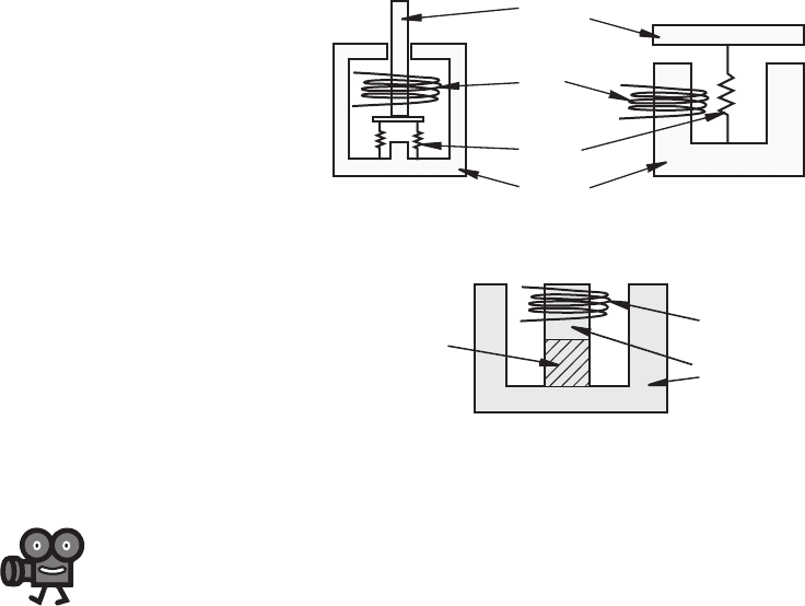
As illustrated in Figure 10.2 , a solenoid consists of a coil and a movable iron core
called the armature. When the coil is energized with current, the core moves to
increase the flux linkage by closing the air gap between the cores. The movable core
is usually spring-loaded to allow the core to retract when the current is switched off.
The force generated is approximately proportional to the square of the current and
inversely proportional to the square of the width of the air gap. Solenoids are inex-
pensive, and their use is limited primarily to on-off applications such as latching,
locking, and triggering. They are frequently used in home appliances (e.g., washing
machine valves), automobiles (e.g., door latches and the starter solenoid), pinball
machines (e.g., plungers and bumpers), and factory automation. Video Demos 10.1
through 10.3 show examples of interesting student projects using solenoids in cre-
ative ways.
An electromechanical relay is a solenoid used to make or break mechanical con-
tact between electrical leads. A small voltage input to the solenoid controls a poten-
tially large current through the relay contacts. Applications include power switches
and electromechanical control elements. A relay performs a function similar to a
power transistor switch circuit but has the capability to switch much larger currents.
Video Demo
10.1Magic piano
10.2Automated
melodica
10.3LED
fountain system
alc80237_ch10_431-477_sss.indd 433alc80237_ch10_431-477_sss.indd 433 10/01/11 10:24 PM10/01/11 10:24 PM
Confirming Pages
Figure 10.2 Solenoids.
(a) plunger type
(b) nonplunger type
movable
armature
core
coil
stationary
iron core
spring
spring
434 CHAPTER 10 Actuators
Relays, because they create a mechanical connection and don’t require voltage bias-
ing, can be used to switch either DC or AC power. Also, the input circuit of a relay
is electrically isolated from the output circuit, unlike the common-emitter transistor
circuit, where there is a common ground between the input and output. Because
the relay is electrically isolated, noise, induced voltages, and ground faults occur-
ring in the output circuit have minimal impact on the input circuit. One disadvan-
tage of relays is that they have slower switching times than transistors. And because
they contain contacts and mechanical components, they wear out much faster. Video
Demo 10.4 demonstrates how relays and transistors respond to different switching
speeds.
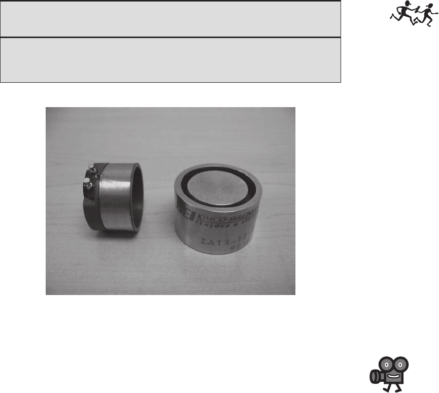
As illustrated in Figure 10.3 , a voice coil consists of a coil that moves in a
magnetic field produced by a permanent magnet and intensified by an iron core.
Figure 10.4 shows the coil and iron core of a commercially available voice coil,
which can be used as either a sensor or an actuator. When used as an actuator, the
force on the coil is directly proportional to the current in the coil. The coil is usually
attached to a movable load such as the diaphragm of an audio speaker, the spool of
a hydraulic proportional valve, or the read-write head of a computer disk drive. The
linear response, small mass of the moving coil, and bidirectional capability make
voice coils more attractive than solenoids for control applications.
Video Demos 10.5 and 10.6 show how a computer disk drive functions, where a
voice coil is used to provide the pivoting motion of the read-write head. Video Demo
10.7 shows a super-slow-motion clip, filmed with a special high-speed camera,
which dramatically demonstrates the accuracy and speed of the voice coil motion.
The read-write head comes to a complete stop on one track before moving to another.
In real-time (e.g., in Video Demo 10.6), this motion is a total blur.
Video Demo
10.4Relay
and transistor
switching circuit
comparison
10.5Computer
hard-drive with
voice coil
10.6Computer
hard-drive
track seeking
demonstration
10.7Computer
hard-drive super-
slow-motion video
of track finding
Figure 10.3 Voice coil.
movable
coil
stationary
iron core
permanent
magnet
N
S
alc80237_ch10_431-477_sss.indd 434alc80237_ch10_431-477_sss.indd 434 10/01/11 10:24 PM10/01/11 10:24 PM
Confirming Pages
10.4 ELECTRIC MOTORS
Electric motors are by far the most ubiquitous of the actuators, occurring in virtually
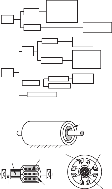
all electromechanical systems. Electric motors can be classified either by function or
by electrical configuration. In the functional classification, motors are given names
suggesting how the motor is to be used. Examples of functional classifications
include torque, gear, servo, instrument servo, and stepping. However, it is usually
necessary to know something about the electrical design of the motor to make judg-
ments about its application for delivering power and controlling position. Figure 10.5
provides a configuration classification of electrical motors found in mechatronics
applications. The differences are due to motor winding and rotor designs, resulting
in a large variety of operating characteristics. The price-performance ratio of electric
motors continues to improve, making them important additions to all sorts of mecha-
tronic systems from appliances to automobiles. AC induction motors are particularly
important in industrial and large consumer appliance applications. In fact, the AC
induction motor is sometimes called the workhorse of industry. Video Demos 10.8
through 10.10 show some examples and describe how the motors function.
Video Demo
10.8AC
induction motor
(single phase)
10.9AC
induction motor
with a soft start for
a water pump
10.10AC
induction motor
variable frequency
drive for a building
air handler unit
■ CLASS DISCUSSION ITEM 10.1
Examples of Solenoids, Voice Coils, and Relays
Make a list of common household and automobile devices that contain solenoids,
voice coils, and relays. Describe why you think the particular component was
selected for each of the devices you cite.
Figure 10.4 Photograph of a voice coil iron core and coil.
10.4 Electric Motors 435
alc80237_ch10_431-477_sss.indd 435alc80237_ch10_431-477_sss.indd 435 10/01/11 10:24 PM10/01/11 10:24 PM
Confirming Pages
DC
motors
single
phase
induction
synchronous
shaded pole
hysteresis
reluctance
permanent magnet
polyphase
synchronous
universal motor
AC
motors
wound rotor
squirrel cage
induction
wound rotor
squirrel cage
brushed
brushless
permanent magnet
variable reluctance
series wound
shunt wound
compound wound
permanent magnet
variable reluctance
Figure 10.5 Configuration classification of electric motors.
436 CHAPTER 10 Actuators
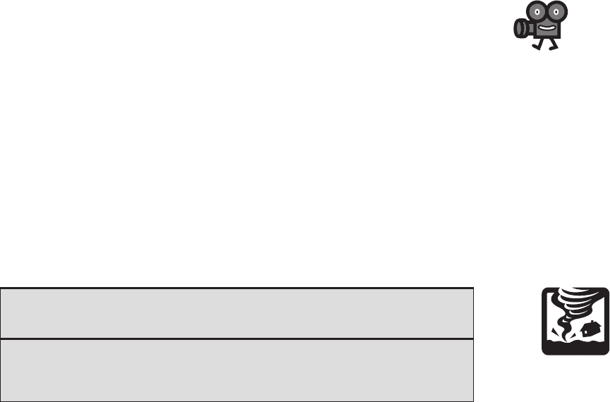
Figure 10.6 illustrates the construction and components of a typical electric
motor. The stationary outer housing, called the stator, supports radial magnetized
poles. These poles consist of either permanent magnets or wire coils, called field
coils, wrapped around laminated iron cores. The purpose of the stator poles is to pro-
vide radial magnetic fields. The iron core intensifies the magnetic field inside the coil
due to its permeability. The purpose for laminating the core is to reduce the effects
of eddy currents, which are induced in a conducting material (see Class Discussion
Item 10.2). The rotor is the part of the motor that rotates. It consists of a rotating
shaft supported by bearings, conducting coils usually referred to as the armature
windings, and an iron core that intensifies the fields created by the windings. There
Figure 10.6 Motor construction and terminology.
stator
shaft/rotor
air gap
shaft
commutator
segment
laminated iron core pole
winding
bearing
rotor
stator (end view section)
winding
laminated
iron core
pole
rotor
alc80237_ch10_431-477_sss.indd 436alc80237_ch10_431-477_sss.indd 436 10/01/11 10:24 PM10/01/11 10:24 PM
Confirming Pages
is a small air gap between the rotor and the stator where the magnetic fields interact.
In many DC motors, the rotor also includes a commutator that delivers and con-
trols the direction of current through the armature windings. For motors with a com-
mutator, “brushes” provide stationary electrical contact to the moving commutator
conducting segments. Brushes in early motors consisted of bristles of copper wire
flexed against the commutator, hence the term brush; but now they are usually made
of graphite, which provides a larger contact area and is self-lubricating. The brushes
are usually spring-loaded to ensure continual contact with the commutator. Video
Demo 10.11 shows a small, brushed, permanent-magnet DC motor disassembled so
you can see the various components and how they function.
A brushless DC motor has permanent magnets on the rotor and a rotating field
in the stator. The permanent magnets on the rotor eliminate the need for a commuta-
tor. Instead, the DC currents in the stator coils are switched in response to proximity
sensors that are triggered as the shaft rotates. Video Demos 10.12 and 10.13 show
two examples of brushless DC motors. One advantage of a brushless motor is that
it does not require maintenance to replace worn brushes. Also, because there are no
rotor windings or iron core, the rotor inertia is much smaller, sometimes making
control easier. There are also no rotor heat dissipation problems, because there are no
rotor windings and hence no I
2
R heating. Another advantage of not having brushes
is that there is no arcing associated with mechanical commutation. Therefore, brush-
less motors create less EMI and are more suitable in environments where explosive
gases might be present. One disadvantage of brushless motors is that they can cost
more due to the sensors and control circuitry required.
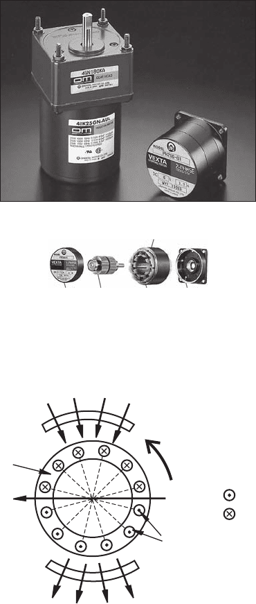
Figure 10.7 shows examples of commercially available assembled motors. In
the top figure, the motor on the left is an AC induction motor with a gearhead speed
reduction unit attached. The motor on the right is a two-phase stepper motor. Motors
come in standard sizes with standard mounting brackets, and they usually include
nameplates listing some of the motor’s specifications. The bottom figure shows the
internal construction of a permanent-magnet-rotor stepper motor. Video Demo 10.14
shows other examples of commercially available regular DC motors and stepper
motors.
Video Demo
10.11DC motor
components
10.12Brushless
DC motor from a
computer fan
10.13Brushless
DC motor gear
pump
10.14DC and
stepper motor
examples
■ CLASS DISCUSSION ITEM 10.2
Eddy Currents
Describe the causes of eddy currents that are induced in a conducting material expe-
riencing a changing magnetic field. The iron core in a motor rotor is usually lami-
nated. Explain why. What is the best orientation for the laminations?
Torque is produced by an electric motor through the interaction of either stator
fields and armature currents or stator fields and armature fields. We illustrate both
principles starting with the first. Figure 10.8 illustrates a DC motor with six armature
windings. The direction of current flow in the windings is illustrated in the figure.
10.4 Electric Motors 437
alc80237_ch10_431-477_sss.indd 437alc80237_ch10_431-477_sss.indd 437 10/01/11 10:24 PM10/01/11 10:24 PM
Confirming Pages
438 CHAPTER 10 Actuators
As a result of Equation 10.1 , the interaction of the fixed stator field and the currents
in the armature windings produce a torque in the counterclockwise direction. You
can verify this torque direction by applying the right-hand rule to the armature cur-
rent and stator field directions. To maintain the torque as the rotor rotates, the spatial
arrangement of the armature currents relative to the stator field must remain fixed.
Figure 10.7 Examples of commercial motors. (Courtesy of Oriental Motor,
Torrance, CA)
(a) AC induction and stepper motor
(b) exploded view of stepper motor with a
permanent magnet rotor
Case
FlangeStatorRotorBracket
Figure 10.8 Electric motor field-current interaction.
1
1
2
2
3
3
4
4
5
5
6
6
stator
stator
stator field
stator field
current out
current in
torque
rotor
armature
windings
armature
field
alc80237_ch10_431-477_sss.indd 438alc80237_ch10_431-477_sss.indd 438 10/01/11 10:24 PM10/01/11 10:24 PM
Confirming Pages
A commutator accomplishes this by switching the currents in the armature windings
in the correct sequence as the rotor turns.
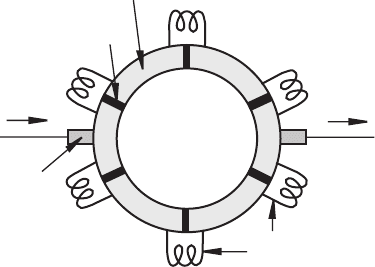
Figure 10.9 illustrates an example commutator. It consists of a ring of alternat-
ing conductive and insulating materials connected to the rotor windings. Current is
directed through the windings via the brushes, which slide on the surface of the com-
mutator as it rotates. In the position shown, the current flows through windings A,
B, and C in the clockwise direction and through F, E, and D in the counterclockwise
direction.
When the rotor turns clockwise one sixth of a full rotation from the position
shown, the currents in windings C and F switch directions. As the brushes slide over
the rotating commutator, this process continues in sequence. With appropriate wind-
ing configurations, the commutator maintains a consistent spatial arrangement of the
currents relative to the fixed stator fields. This continually maintains the torque in the
desired direction.
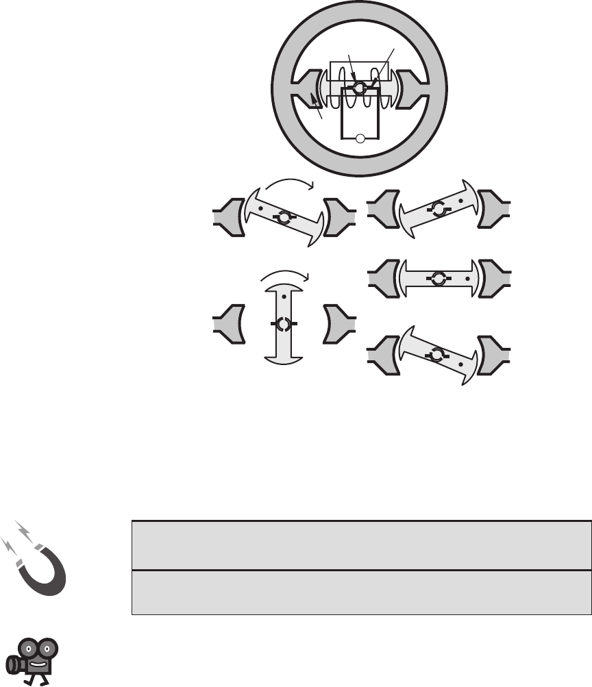
Another method by which electric motors can create torque is through the inter-
action of stator and rotor magnetic fields. The torque is produced by the fact that
like field poles attract and unlike poles repel. Figure 10.10 illustrates this principle
of operation with a simple two-pole DC motor. The stator poles generate fixed mag-
netic fields with permanent magnets or coils carrying DC current. The winding in the
rotor is commutated to cause changes in direction of its magnetic field. The interac-
tion of the changing rotor field and the fixed stator fields produce a torque on the
shaft, causing rotation. With the rotor in position i, the right brush contacts commu-
tator segment A and the left brush contacts segment B, creating a current in the rotor
winding, resulting in the magnetic poles as shown. The rotor magnetic poles oppose
the stator magnetic poles, creating a torque causing clockwise motion of the rotor.
In position ii, the stator poles both oppose and attract the rotor poles to enhance
the clockwise rotation. Between positions iii and v the commutator contacts switch,
changing the direction of the rotor current and hence the direction of the magnetic
field. In position iv, both brushes temporarily lose contact with the commutator, but
Figure 10.9 Electric motor six-winding commutator.
A
B
C
D
E
F
armature
windings
I
in
I
out
brush
conductor
insulator
10.4 Electric Motors 439
alc80237_ch10_431-477_sss.indd 439alc80237_ch10_431-477_sss.indd 439 10/01/11 10:24 PM10/01/11 10:24 PM
Confirming Pages
Figure 10.10 Electric motor field-field interaction.
+
stator
N
S
A
B
commutator
segment
brush
stator
pole
torque
(i)
N S
A
B
N
S
(iii)
N S
A
B
N
S
A
B
(iv)
N S
(v)
N S
B
A
S
N
(ii)
N
S
AB
N
S
Video Demo
10.11DC motor
components
440 CHAPTER 10 Actuators
the rotor continues to move due to its momentum. In position v reversed magnetic
field in the rotor again opposes the stator field, continuing the clockwise torque and
motion.
■ CLASS DISCUSSION ITEM 10.3
Field-Field Interaction in a Motor
Does the armature field in Figure 10.8 have any effect on the torque produced by
the motor?
A problem with the simple two-pole design illustrated in Figure 10.10 is that
starting would not occur if the motor happens to be in position iv, where the brushes
are located over the commutator gaps. This problem can be avoided by designing the
motor with more poles and more commutator segments with overlapping switching.
This allows the brushes to always contact two active segments, even while switching
(see Video Demo 10.11 and Class Discussion Item 10.4).
alc80237_ch10_431-477_sss.indd 440alc80237_ch10_431-477_sss.indd 440 10/01/11 10:24 PM10/01/11 10:24 PM
