Woodyard D. (ed.) Pounders Marine diesel engines and Gas Turbines
Подождите немного. Документ загружается.

and without disturbing the rest of the engine. The exhaust manifolds feature
sliding joints and, like the turbochargers, are housed in water-cooled gas-tight
aluminium casings; together with the turbocharger enclosure, they form a sin-
gle, cool gas-tight shell around the hot parts of the engine. The casings foster
low radiant and convective heat losses from the engine.
The gear train is mounted at the engine’s free end, the camshaft gearwheel
meshing directly with the crankshaft gearwheel. Auxiliary drives are provided
for the externally mounted lubricating oil and jacket water pumps, the gover-
nor, overspeed governor and fuel lift pump; further auxiliary power take-off
capability is incorporated for different applications. The PTO at the free end
accepts either gear-driven or belt-driven pumps and alternators. The VP185
was supplied as a complete assembly with engine-mounted jacket water and
lubricating oil heat exchangers to simplify installation procedures. A choice of
air, electric or hydraulic starting systems was available.
Marine engine versions are controlled by a Regulateurs Europa digital
Viking 2200 governor and 2231 actuator with the option of ball head back-up.
Multiple Schwitzer turbochargers in a passive two-stage configuration with
intercooling and aftercooling were retained for the V18-cylinder model, albeit
with an increased number of sets. Three HP turbochargers each expand into a
pair of similar LP turbochargers, giving a total of nine turbochargers. Unlike the
12VP185 engine, the turbochargers are packaged in groups of three (one HP
and two LP), each group having its own water-cooled gas-tight housing. The hot
turbine volutes are fixed to the inside of each housing, with the rest of the tur-
bocharger, the ‘cartridge’, plugged in from the outside: an arrangement which
paxman (man Diesel) 811
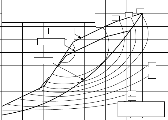
A1 : High-speed craft, 4000 kWb, 1950 r/min at air 25°C,
sea water 25°C
A2 : High-speed commercial craft, 3300 kWb, 1830 r/min
B : Long-range patrol craft, 3000 kWb at 1770 r/min at
air 45°C, sea water 25°C
Torque limit A1
200
205
210
215
225
240
260
280
Specific fuel consumption
g/kW h (…0%, +5%) at
Air 25°C, seawater 25°C
195
Torque limit A2
Cube law
600 800 1000 1200 1400 1600 1800 2000 2200
Engine speed (r/min)
4500
4000
3500
3000
2500
2000
1500
1000
500
0
Engine power (kW)
FigurE 30.32 performance map for paxman 18vp185 engine
812 High-Speed Engines
enables the turbochargers to be replaced quickly. The hot exhaust manifold pipes
are similarly housed in their own water-cooled gas-tight casings, so eliminating
unwanted heat and gas around the engine (an important safety aspect).
SEmt-piElStiCK
The Paris-based designer SEMT-Pielstick fielded three long-established high-
speed programmes, the PA4, PA5 and PA6 series, before and after its acquisi-
tion first by MTU and MAN B&W Diesel and then wholly by MAN Diesel.
Some engines are still produced for special land-based and submarine applica-
tions but not for mainstream marine markets.
The PA4 series, produced in 185 mm and 200 mm bore versions (both hav-
ing a stroke of 210 mm), featured a variable geometry (VG) pre-combustion
chamber; while the PA5 is a 255 mm bore/270 mm stroke design.
Development benefited the 280 mm bore PA6 design, introduced in 1971
with a stroke of 290 mm and a maximum continuous rating of 258 kW/cylin-
der at 1000 rev/min. The output was raised to 295 kW/cylinder in 1974 and
to 315 kW/cylinder in 1980. Extensive service experience in naval vessels
moulded progressive refinements over the years, including the creation of a
BTC version in 1980 which yielded 405 kW/cylinder at 1050 rev/min through
the adoption of a reduced compression ratio in conjunction with two-stage tur-
bocharging. This PA6 BTC model was released in 1985 with a higher output of
445 kW/cylinder. The series was extended in 1983 by a longer stroke (350 mm),
slower speed PA6 CL variant with a rating of 295 kW/ cylinder at 750 rev/min.
A sequential turbocharging system (STC) was introduced to the 290 mm
stroke engine in 1989, this PA6 STC model developing 324 kW/cylinder at
1050 rev/min. Performance was enhanced in a 330 mm stroke B-version from
1994, an STC system and a cylinder head with improved air and gas flow rates
contributing to a nominal maximum continuous rating of 405 kW/cylinder at
1050 rev/min. A maximum sprint rating of 445 kW/cylinder at 1084 rev/min
equated to an output of 8910 kW from the V20-cylinder PA6B STC engine
which targeted high-performance vessels such as fast ferries.
At the nominal mcr level the V12-, 16- and 20-cylinder models respec-
tively offered 4860 kW, 6480 kW and 8100 kW for fast ferry propulsion, being
released for sustained operation at these ratings. The weight/power ratio of the
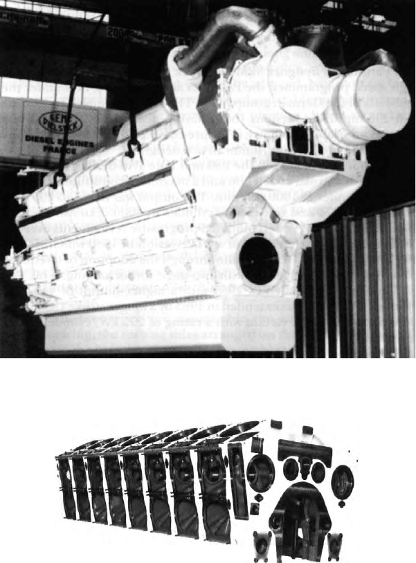
20PA6B STC model at 8100 kW is 5.2 kg/kW (Figure 30.33).
pa6B StC Design
High rigidity without compromising overall engine weight was achieved by a
stiff one-piece crankcase (Figure 30.34) of nodular cast iron specially treated
for shock resistance, with transverse bolt connections between both crankcase
sides through the underslung-type bearing caps. Integrated longitudinal steel
piping supplies lubricating oil to the main bearings.
Large dimension main journals yield a particularly large bearing surface
and conservative pressures which underwrite prolonged bearing life, as do
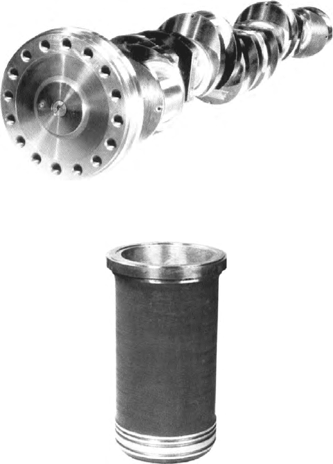
the large surface area connecting rod bearing shells. The alloy steel one-piece
forged crankshaft (Figure 30.35) has high frequency hardened crankpins and
journals, and is bored to feed lubricating oil to the connecting rods.
A nodular cast iron cylinder head was configured to achieve improved
air and gas flow rates for the PA6B STC version. The composite piston (steel
crown and aluminium skirt) is fitted with five rings. The forged steel connect-
ing rod is fitted with large surface bearing shells to yield high durability under
high firing pressures. Special low-wear characteristics were sought from the
centrifuged cast iron material specified for the cylinder liner (Figure 30.36).
The camshaft is formed from several sections for ease of dismantling.
SEmt-pielstick 813
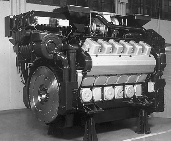
FigurE 30.33 SEmt-pielstick v20-cylinder pa6B StC engine with sequential turbo-
charging system; a rating of 8100 kW was oered for fast ferry propulsion
FigurE 30.34 SEmt-pielstick pa6B StC crankcase
814 High-Speed Engines
Operational flexibility and power output are fostered by the single-
stage sequential turbocharging system which is based on two turbochargers
and delivers a large combustion air excess at partial loads. Supercharging is
effected by one turbocharger for engine loads up to 50 per cent of the nomi-
nal power, its effort boosted by the second identical turbocharger at higher
loads. Switching from single to twin turbocharger mode is performed auto-
matically by opening two flap valves. Engine performance at prolonged low
load is thereby improved with respect to fuel consumption, smoke emissions,
fouling resistance and transient performance. Additionally, engine utilization is
expanded towards the high torque/low revolutions per minute area.
Developing the High-performance Derivative
Refining an established engine for high-speed vessel propulsion duty must
focus on achieving a lighter and more powerful package within a more com-
pact envelope, while also enhancing operating flexibility. The resulting
FigurE 30.35 SEmt-pielstick pa6B StC crankshaft
FigurE 30.36 SEmt-pielstick pa6B StC cylinder liner
PA6B STC design was released with a nominal maximum continuous rating
of 405 kW/cylinder at 1050 rev/min and a sprint rating of 445 kW/cylinder at
1084 rev/min (Figure 30.37).
SEMT-Pielstick’s development goals aimed to:
l Increase the power rating by 25 per cent.
l Use an operating field allowing operation following a double propeller
law.
SEmt-pielstick 815
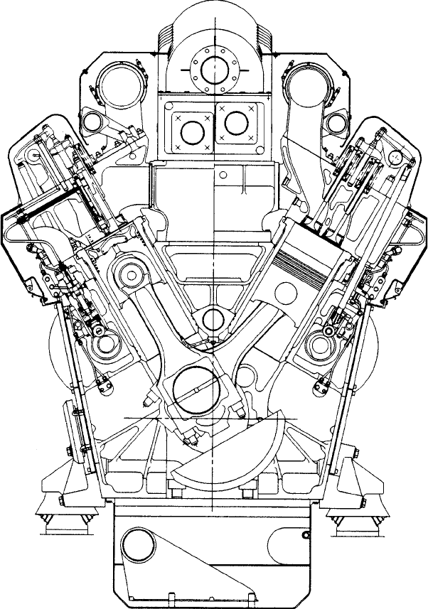
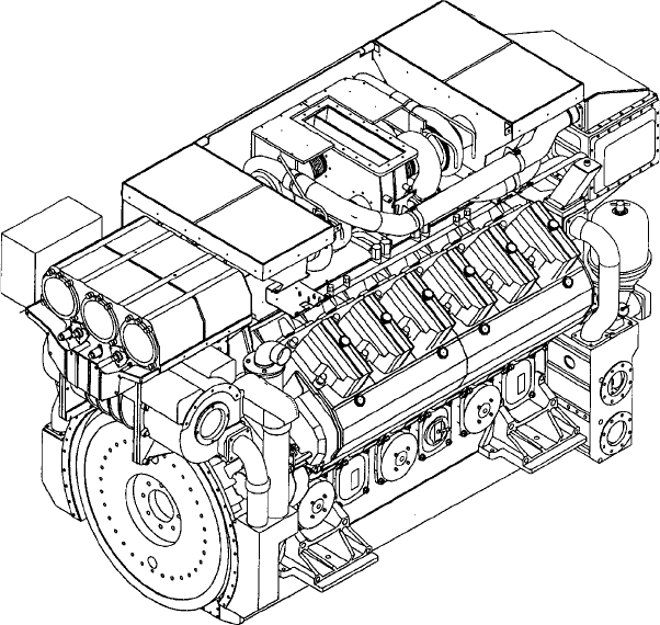
FigurE 30.37 Cross-section of SEmt-pielstick pa6B StC engine
816 High-Speed Engines
l Maintain, and if possible reduce, the specific fuel consumption.
l Reduce the weight/power ratio and enhance engine compactness.
l Reduce installation costs.
l Retain the maximum number of existing components.
Power can be raised in two ways: by increasing the brake mean effec-
tive pressure and by increasing the piston speed. Increasing piston speed can
be effected by increasing the revolutions per minute and by lengthening the
stroke. Increasing the revolutions per minute was not attractive because of a
need to maintain an acceptable synchronized speed for land power plant appli-
cations but also because of these drawbacks: increased specific fuel consump-
tion; higher wear rate; and higher noise levels.
Raising piston speed by lengthening the stroke is considered preferable
because it reduces specific fuel consumption and fosters optimum performance
at starting and low load (the compression ratio is secured without resorting to a
combustion chamber that is too flat). This route was therefore selected but with
the piston speed limited to 11.5 m/s (representing an increase of 14 per cent
with a stroke of 330 mm). To reach the required power rating, the brake mean
effective pressure had to be increased by 10 per cent; this was achieved by
adopting high-performance turbochargers. Attaining the desired specific fuel
consumption called for the maximum cylinder pressure to be raised to 160 bar.
Coping with these new parameters dictated redesigning some key compo-
nents. The existing cylinder head, for example, was incompatible with the tar-
geted specific fuel consumption level. This was partly because its mechanical
strength was insufficient in relation to the necessary peak combustion pressure,
and partly because the pressure loss through the inlet and exhaust ports would
be unacceptable in relation to the intervening gas flow dictated by the increased
power. A new cylinder head was therefore designed with a reinforced bore-
cooled fire plate and incorporating inlet and exhaust ports with large dimen-
sions. In addition, cooled seats were specified for the inlet valves as well as the
exhaust valves to maximize seat reliability and avoid risks of burning.
A redesigned connecting rod was also necessary to address the increased
peak compression pressures and the inertia efforts linked to the lengthening of
the stroke. The bevel-cut design of the original component was abandoned in
favour of a straight-cut rod to avoid weak points, such as the bevel-cut serra-
tions and the threading anchorage in the shank. Piston cooling by jet replaced
the traditional oil supply through the connecting rod from the crankpin, simpli-
fying machining and allowing the bearing shell grooves to be eliminated and
yield these benefits: increasing capacity of the bearing shells; stopping cam
wear of the crankpin (differential wearing of the pins between the side areas
of the plain bearing shell and the central area; that is, the area including the
groove); and cutting out the risk of cavitation erosion on the bearing shells at
the end of the grooves. The new connecting rod is 10 per cent lighter than its
bevel-cut forerunner. The weight reduction, along with an improved bearing
shell capacity, partly compensates for the increased inertia efforts.
Temperature measurements on the jet-cooled piston head indicated simi-
lar levels to those of the original piston, and even lower in some areas. Critical
points of the piston were modified to cope with the higher peak combustion
pressure: a spherical shape was given to the support spot face used for the piston
head/skirt tightening spacers; and the radius under the skirt vault was increased.
Crankshaft dimensions were modified to target the same reliability from
the component as before, despite the increased stroke and peak combustion
pressure. Finite element analyses of the crank webs and hydrodynamic calcula-
tions led to an increase in the journal diameter from 230 mm to 250 mm, and in
the crankpin diameter from 210 mm to 230 mm.
High-performance turbochargers were necessary to secure the brake mean
effective pressure increase with the required efficiency, a model from MAN
B&W’s then new NA series—the NA 34S—being selected to meet the perform-
ance and compactness parameters. Sequential turbocharging was applied, based on
the principle of reducing the number of turbochargers in operation as the engine
speed and load fall. The speed of the turbochargers still operating consequently
rises and significantly larger quantities of air are thus delivered to the engine.
A simple system was adopted using only two turbochargers, one being
switched off at below approximately 50 per cent of the nominal engine power rat-
ing. This was effected by closing two flap valves located at the compressor outlet
and at the turbine inlet of one of the turbochargers. The designer cited the follow-
ing benefits from the PA6 engine’s sequential turbocharging (STC) system:
l High torque and power ability at reduced engine speed.
l A gain in fuel economy at low and part loads.
l Capability to run the engine at very low loads for extended periods with
minimal fouling (the light deposits can be cleaned out by running for
half an hour at 50 per cent load).
l Invisible smoke emissions over a wide working range.
l Reduced exhaust temperature.
l Lower thermal stresses in the combustion chamber components at part
loads.
A higher output rating naturally reduced the engine’s weight/power ratio
but other measures were pursued to trim overall weight. The scope for using
aluminium alloy was explored for all components where operating stresses
(particularly thermal) and class rules allowed, leading to the engine supports,
turbocharger support, air manifolds (after the air cooler), lube oil and water
cooler support, and lube oil filter support being designed in cast aluminium.
Studies assessed other components for which aluminium could not be consid-
ered, either to use alternative materials with higher mechanical properties and
so reduce thickness, or simply to optimize existing shapes and thicknesses. As
an example, specifying high yield point steel sheet for the manifolds connect-
ing the turbocharger to the air cooler allowed a reduction in thickness from
10 mm to 4 mm. The lube oil sump plate was also modified by reducing the
material thickness.
SEmt-pielstick 817
818 High-Speed Engines
A 10 per cent reduction in the original engine weight, along with the
increased power output, contributed to a weight/power ratio of 4.8 kg/kW, includ-
ing all ancillaries. In parallel with the weight trimming studies, SEMT-Pielstick
focused on reducing the overall dimensions of both engine and ancillaries.
A key element in this regard was the combi-cooler, integrating one lube
oil and one freshwater plate cooler circulated by a common sea water sys-
tem (Figure 30.38). The combi-cooler’s support is used as the rear plate of
the cooler and includes as-cast part of the connections to the HT freshwater
and lube oil systems. Its front plate incorporates as-cast the connections to the
LT freshwater loop and the water thermostatic valve. The main self-cleaning
lube oil filter is incorporated axially in a cast support located under the combi-
cooler, and includes the lube oil thermostatic valve as well as the centrifugal
oil filters.
Such solutions fostered compactness, a simple pipeless configuration and
good access to the main subjects of maintenance. Integration of the ancillar-
ies on the engine further eases shipboard installation procedures. All pumps
(water, oil, fuel make-up), as before, are driven by the engine upon which the
fuel filter is also mounted.
A potential for burning an intermediate fuel oil grade such as IF30 was
addressed in the development programme, and reflected in the specification of
cooled valve seats and exhaust valve rotators. The 75°C temperature necessary to
reach an adequate viscosity for its injection could be derived by taking heat from
the engine’s HT freshwater system. In such installations, however, the engine
was derated to 360 kW/cylinder and the time-between-overhauls reduced.
WärtSilä
The medium-speed specialist Wärtsilä added high-speed designs to its four-
stroke engine portfolio with the acquisition in 1989 of SACM Diesel of France.
Engine outlet
Engine
inlet
Freshwater
drive pump
Freshwater circuit
Air cooler
Sea water circuit
Sea water-
driven pump
Oil cooler
Freshwater
cooler
Combi-cooler
FigurE 30.38 Fresh and sea water circuits integrated on the pa6B StC engine
The Finnish parent group saw the market potential for a new generation engine
blending the best features of high- and medium-speed designs for continu-
ous duty applications, resulting in the 1994 launch of the Wärtsilä 200 series
(Figures 30.39 and 30.40).
The 200 mm bore/240 mm stroke engine was produced by Wärtsilä
France for propulsion and genset drive applications, with an output band from
2100 kW to 3600 kW at 1200 rev/min or 1500 rev/min covered by V12-, 16-
and 18-cylinder models. High reliability in continuous duty (defined as 24 h a
day operation with an annual running period of over 6000 h) was sought from
an engine structure and main components designed for a maximum cylinder
pressure of 200 bar. Wärtsilä’s medium-speed engine technology was exploited
to achieve a high power density, low emissions and fuel consumption, and ease
of maintenance. Although W200 engine production was comparatively short
lived, its innovative features are worthy of study by engine designers.
A multi-functional connection piece or ‘multi-duct’ located between the
cylinder head, engine block and exhaust manifold has the following duties:
l Combustion air transfer from charge-air receiver to cylinder head.
l Introduction of an initial swirl to the inlet air for optimal part-load
combustion.
l Exhaust gas transfer to the exhaust system.
l Cooling water transfer from the cylinder head to the return channel in
the engine block.
Wärtsilä 819
FigurE 30.39 Wärtsilä W200 engine
820 High-Speed Engines
l Insulation/cooling of the exhaust transfer port.
l Support for the exhaust manifold and insulation.
l Inclined face towards the cylinder head facilitates easy removal/
remounting of the cylinder head. The exhaust gas piping and insula-
tion box, supported by the multi-duct, stay in place when the head is
removed.
The nodular cast iron engine block was designed for maximum stiffness
with a V60° configuration optimizing balancing and hence limiting vibra-
tion. Bolted supports dictate only four to six fixing points, and provision is
made for elastic mounting. The locations of the camshaft drive (integrated
in the flywheel end of the block) and the air receiver channel (in the middle
of the vee-bank and also integral with the block) reflect solutions adopted in
Wärtsilä medium-speed engines. Arranging the oil lubrication distribution
through a channel in the middle of the vee, however, was a new idea. The areas
of the block that support the camshafts and fuel injection pumps are designed
for high strength to accept the forces created by the high injection pressures.
Large openings on both sides of the block facilitate access for inspection and
maintenance.
FigurE 30.40 Wärtsilä W200 engine. the original automotive-type turbochargers
shown here were later replaced by aBB or Holset models