Woodyard D. (ed.) Pounders Marine diesel engines and Gas Turbines
Подождите немного. Документ загружается.

Structurally, the Series 8000 is the first MTU engine to feature modular
‘power units’, which can be quickly removed and replaced (Figure 30.19).
Each integrated module comprises:
l A cylinder head, including valve gear, fuel injector, exhaust T-piece and
coolant line segment.
l Cylinder liner.
l Piston and connecting rod.
l Spacer (for channelling coolant to the upper section of the liner and to
the coolant pipes).
Each power unit is attached to the crankcase by four hydraulically tight-
ened stud bolts which have to withstand the high ignition pressures but do not
perform a sealing function. A good seal is effected by securing the cylinder
liner directly to the cylinder head from below with 24 bolts. By separating the
functions of sealing and retention, MTU explains, wider design scope was cre-
ated for optimizing the channels, valve gear and cylinder head cooling.
High design rigidity and endurance strength were sought from the transverse-
flow nodular grey cast iron cylinder head. Its exhaust ports and particularly
the inlet ports are said to yield excellent flow coefficients which establish the
fundamental conditions for fuel economy and low emission levels. Circularity
of the cylinder liner when the engine is running is sustained by the 24 evenly
spaced bolts around its perimeter and by which it is attached to the cylinder
motoren- und turbinen-union 791
C-B2 C-B1
Exh.
flap
Exhaust
gas diffuser
T
T
C-A2 C-A1
Air flap
Carrier
housing
CAC
CAC
B1B2B3B4B5B6B7B8B9
B10
A1A2A3A4A5A6A7A8A9
A10
Air C: Compressor CAC: Charge-air cooler
Exhaust gas T: Turbine MDEC: MTU Diesel Engine Control
MDEC
T
T
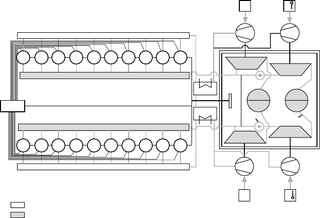
FigurE 30.18 thermodynamic model of the mtu 20 v 8000 m70 engine and its
sequential turbocharging system
792 High-Speed Engines
head. That circularity underwrites highly efficient sealing by the piston rings
and, combined with a special liner honing process developed by MTU, pro-
motes smooth running and durability. The high sealing efficiency of the rings
and liners is also the basis for the ‘exceptionally low blow-by levels’ dem-
onstrated by the Series 8000 engine, the designer reports. This significantly
extends the life of the lubricating oil by reducing the amount of dirt escaping
past the rings.
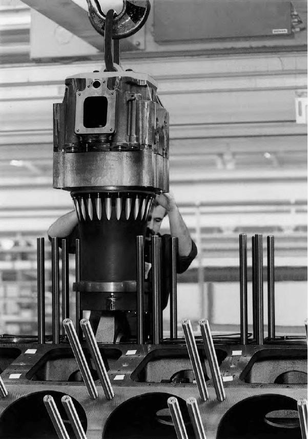
FigurE 30.19 all the cylinder components of the mtu Series 8000 engine are
combined in a functional module termed a ‘power unit’ for ease of withdrawal and
replacement
A robust nodular cast iron crankcase extending well below the centreline
of the crankshaft is described as particularly rigid, the structure offering large
inspection ports to ease checking and maintenance. Integrated in the crank-
case are large lateral charge-air ducts to the cylinders, the central bore for the
camshaft operating the valve gear and a centrally located main oil gallery. The
cylinder liner is cooled only in its upper region and the crankcase is therefore
completely coolant free.
Wide, cross-bolted bearing caps retain the crankshaft with its bolt-on coun-
terweights. Both big end and crankshaft main bearings are of the micro-groove
type, and the latter can be replaced in-situ. Other key elements of the running
gear are fully machined connecting rods with diagonally split big ends, and
composite pistons comprising a forged steel skirt (for the first time in an MTU
engine) bolted to a steel crown carrying two compression rings and an oil con-
trol ring. The pistons are cooled by nozzles spraying cooling oil.
Exceptional engine rigidity imparted by the power unit concept, and conse-
quently low-wear characteristics, were expected to help keep lube oil consump-
tion at a constantly low level throughout the period between major overhauls.
Confidence in a promised overhaul interval of up to 24 000 running hours—
depending on the engine’s load profile and power rating—was supported by trials
during which the test engines were subjected to an extremely severe alternating
load sequence as well as continuous operation at full and overload powers.
Minimizing the number and complexity of necessary interfaces, the pumps
for engine coolant, raw water, fuel (HP and LP) and lube oil, as well as the
associated filters and oil coolers, are mounted on the engine. The electronic
MDEC engine management unit is also arranged here. Locating all these
components together as a ‘service block’ on the free end of the engine fosters
accessibility and simplifies integration of the engine with the ship’s systems.
Installation work is further reduced by an engine mounting concept proven
with the Series 1163 engine in many high-speed ferries, the torsionally resil-
ient, offset-accommodating shaft couplings and a special arrangement of the
air intake and exhaust connections.
Engine starting is effected by an air starter, the sequence incorporating an
initial slow-turn phase which allows engine functioning to be quickly checked
without having to open the decompression valves. This is followed immedi-
ately by the main starting sequence.
Contributing to trouble-free, low-maintenance operation are: an automatic oil
filter and two oil centrifuges in the secondary oil circuit (an indicator filter is fitted
in the return line of the automatic filter for monitoring purposes); fuel filter car-
tridges with paper elements that can be replaced while the engine is running; and
an engine coolant filter. The circulation systems are also fitted with running-in
filters which trap any dirt that has found its way into the engine fluids during the
installation process.
Adopted from previous MTU engines is the TE cooling system. Raw water
never comes into contact with the engine components and the inlet temperature
of the coolant at the engine can be controlled to suit the operating conditions.
motoren- und turbinen-union 793

794 High-Speed Engines
At low ambient temperatures and/or low engine loads, for example, the recooler
is bypassed so that the coolant remains at a high temperature and heats up the
combustion air. ‘White smoke’ emissions produced by cold engines can thus be
eliminated. At full power, however, the system provides highly efficient cool-
ing and creates the optimum conditions for combustion, both in terms of fuel
economy and NOx emission levels, according to MTU.
MTU 20V 8000 M70 engine data
Bore
265 mm
Stroke 315 mm
Cylinders v20
output/cylinder 410 kW
power, max 9000 kW
power, continuous 8200 kW
rated speed 1150 rev/min
idle speed 380 rev/min
mean eective pressure 24.6 bar
mean piston speed 12.1 m/s
Weight/power ratio 5.3 kg/kW
Weight 43 tonnes
Specic fuel consumption
190–195 g/kW h
Dimensions (l W H) 7.4 m 1.9 m 3.3 m
uprated Series 8000 Design
The V20-cylinder Series 8000 engines have a continuous rating of 8200 kW
in M70 form and a peak power of 9000 kW in M90 form. Customer interest in
higher performance as well as anticipated stricter emission limits stimulated
the development of a 20V 8000 M71 variant of enhanced design with rated
outputs up to 9100 kW, which was unveiled in 2007. A challenge to the design-
ers was to raise the power while improving the engine’s characteristic qualities.
An 11 per cent power increase was achieved with the same bore and stroke
dimensions and rated speed by raising the brake mean effective pressure to
27.3 bar. To avoid increasing the thermal load on the engine, the charge-air
pressure was raised by developing the single-stage turbocharging system. At
rated power the charge-air pressure reaches an absolute value of 4.1 bar. The
high maximum permissible combustion pressure of 230 bar affords sufficient
possibilities for a high compression ratio, thus ensuring that the engine’s start-
ing and idling characteristics with the increased power are as favourable as the
original design.
Classifying the M71 application called for the engine to be run at 10 per cent
overload, thereby achieving an output of 10 000 kW. The resulting 20V 8000
M71 engine was released in both consumption-optimized IMO and emissions-
optimized EPA Tier II variants.
A new combustion process was developed to achieve an improvement in
emissions performance meeting future requirements at all the power output
options without compromising fuel economy. The configuration of the cylinder
crown recess in conjunction with the injection pattern and fuel injector design
was the most important variable in the combustion engineering. Computer-
aided 3D combustion modelling made it possible to refine the design in fewer
steps. Development of the sequential turbocharging system, based on four
MTU ZR265 turbochargers, also contributed to the achievement of low fuel
consumption and minimal smoke levels at low engine speeds.
Continual feedback from 20V 8000 engines in diverse service contributed
to design refinements seeking to maximize reliability and safety, MTU citing
these problems and solutions:
l Wear on the connecting rod axial bearing: coating of the bearing area
reduced the friction and significantly reduced the wear.
l Vibrations on the HP fuel pump were reduced by a new screw design
and optimized piping arrangement.
l Leakages in exhaust pipe gaskets between cylinders and turbochargers:
a modified vee-clamp, improved gasket and E-ring were able to com-
pensate for the higher axial deformation.
l Leakages due to vibration of the coolant water connection pipes to the
turbocharger carrier housing: design changes reduced the vibration level
and eliminated the leakage.
mtu/DDC Designs
An alliance formed by MTU in 1994 with DDC resulted in the creation of two
advanced high-speed designs for joint marketing by the German/US partners,
the Series 2000 and Series 4000 engines, which were launched in 1996. MTU
was responsible for the basic design development of both engines and the vari-
ants for propulsion applications. Both series have proven highly successful in
propulsion and genset drive sectors, benefiting from progressive refinements.
Series 2000
The Series 2000 design, with a 130 mm bore/150 mm stroke, is based on the
Mercedes-Benz 500 commercial vehicle engine (Figure 30.20). Models with
V90° 8, 10, 12 and 16 cylinders cover a propulsion band from 500 kW to
1790 kW, while genset drive applications start from 270 kW. The most powerful
version, intended for yachts, has a maximum speed of 2300 rev/min. A single-
stage turbocharging system is specified as standard but, when special require-
ments regarding power band width and acceleration characteristics are dictated,
Series 2000 engines can benefit from MTU’s sequential turbocharging system.
motoren- und turbinen-union 795
796 High-Speed Engines
Fuel injection, adapted from the commercial vehicle engine, was origi-
nally a solenoid valve-controlled pump/fuel line/injector system, each cylinder
having its own separate injection pump. MTU’s third-generation common rail
injection system was introduced from 2004 to create the more compact and
higher performance Series 2000CR engine, which reportedly set new standards
in power density in its class. The V16-cylinder version delivers 1790 kW from
a package weighing 3380 kg.
Marine versions are fitted with MTU’s TE twin-circuit cooling system
(detailed earlier in the section Series 396 Engine) which fosters an optimum
temperature for all operating conditions: intake air can be heated at idling
speeds or at partial throttle and cooled at full throttle.
Series 4000
A number of notable design and performance features were highlighted by MTU
for the 165 mm bore/190 mm stroke Series 4000 engine whose designers focused
on high reliability and ease of maintenance without compromising compact-
ness (Figures 30.21 and 30.22). A propulsion power band from around 840 kW
to 2720 kW at 2100 rev/min is covered by the V90° 8-, 12- and 16-cylinder
versions.
Testing confirmed fuel economy figures that reportedly set a new standard
for compact engines in the design’s performance class and speed range. A spe-
cific fuel consumption of 194 g/kW h was considered exceptional for an engine
with a power-to-weight ratio of between 2.7 kg/kW and 3.5 kg/kW.
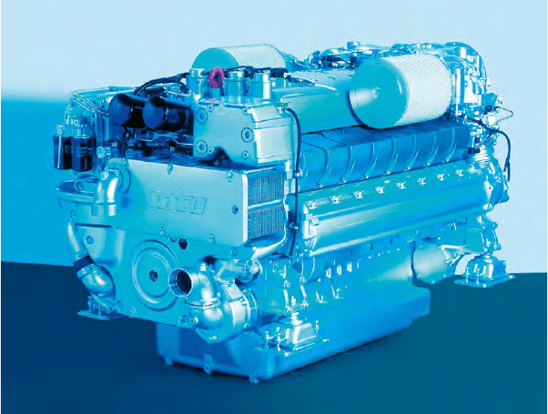
FigurE 30.20 an mtu v16-cylinder Series 2000Cr engine
A key contribution, along with a high peak firing pressure potential, is
made by the common rail fuel injection system—an innovation in this engine
category—whose development was carried out in conjunction with MTU’s
specialist subsidiary company, L’Orange (see Chapter 8).
The system, which allows infinite adjustment of fuel injection timing, vol-
ume and pressure, embraces an HP pump, a pressure accumulator, injectors and
an electronic control unit. The tasks of pressure generation and fuel proportion-
ing are assigned to different components: pressure generation is the job of the
HP pump while metering of the fuel relative to time is the job of the injectors.
The flexibility of the common rail system across the engine power band
enables it to deliver the same injection pressure (around 1200 bar) at all engine
speeds from full-rated speed down to idling (Figure 30.23). The HP fuel pump
and electronically controlled injectors are fully integrated in the ECS. Peak
pressures with the common rail system are around 20 per cent lower than with
conventional systems, reducing stress on the HP components. The pump is also
simpler and its plunger has no helices. Since the pressure-relief requirement
of conventional systems is eliminated, the mechanical effort is reduced, which
further enhances fuel economy.
motoren- und turbinen-union 797
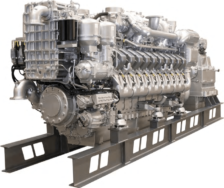
FigurE 30.21 mtu’s upgraded Series 4000 programme includes a v20-cylinder model
delivering up to 4300 kW
798 High-Speed Engines
One fuel rail is provided for the injectors and their respective solenoid
valves on each bank of cylinders. The fuel pressure is generated by the HP
pump driven via a gear train at the end of the crankcase. The electronic system
controls the amount of fuel delivered to the injectors by means of the solenoid
valves, while the injection pressure is optimized according to the engine power
demand. Separate fuel injection pumps for each cylinder are thus eliminated,
and hence the need for a complicated drive system for traditional pumps run-
ning off the camshafts. A reduced load on the camshaft and gearing system is
therefore realized, and the removal of the mounting holes for separate injection
pumps enhances the rigidity of the crankcase.
Maximum strength and optimized rigidity were sought from the crank-
case, with integration of the main lubrication and coolant circulation channels
reducing the number of separate components (Figure 30.24). The crankshaft,
machined all over and with bolted-on counterweights, is designed to withstand
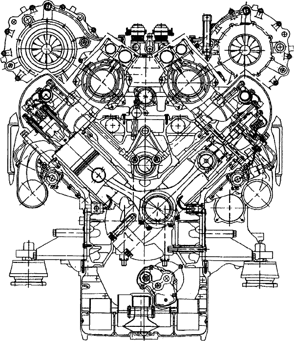
FigurE 30.22 Cross-section of mtu Series 4000 engine
maximum combustion pressures of up to 200 bar. Wear-resistant sleeve bear-
ings contribute to longer service intervals. The cylinder head design, with inte-
grated coolant channels and stiffened base, also addresses a 200 bar pressure.
Provision is made for two inlet and two exhaust valves, and a fuel injector
located in the centre of the head (Figure 30.25).
A piston comprising an aluminium skirt and a bolted-on steel crown is
provided with chrome-ceramic coated rings which, in combination with the
plateau-honed cylinder liner, foster low lubricating oil consumption and an
extended service life. An optimized combustion chamber shape and the bowl of
the composite piston promote low fuel consumption and low emission levels.
motoren- und turbinen-union 799
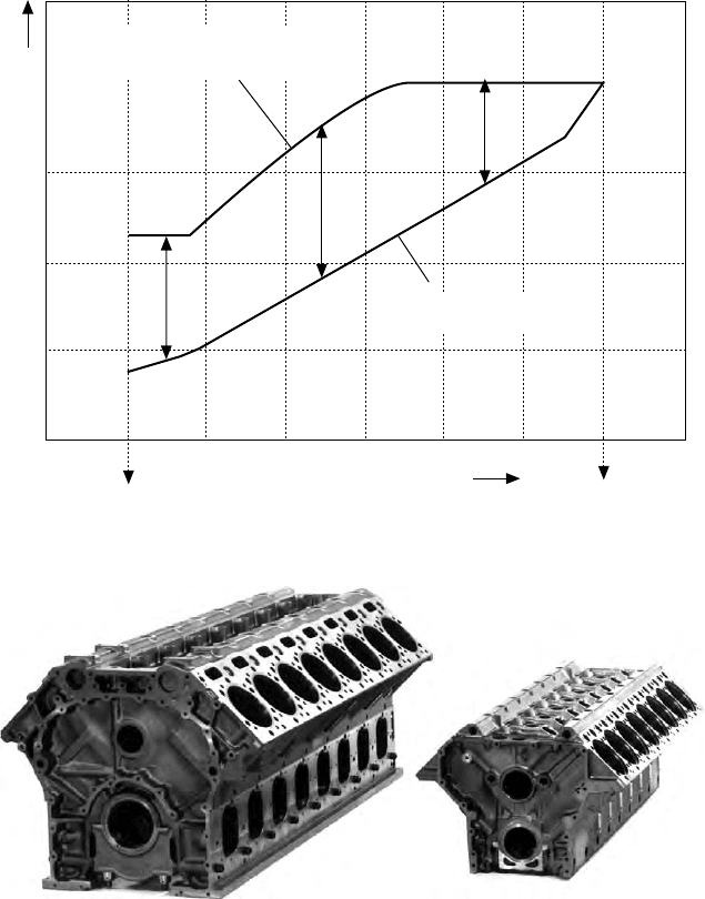
Idle speed
Injection pressure
Optimum injection pressure
with common rail system
Injection pressure with
conventional system
Nominal power
Engine speed
FigurE 30.23 performance of common rail fuel injection system of mtu’s Series
4000 engine
FigurE 30.24 the crankcases of mtu’s Series 2000 (right) and Series 4000 engines (left)
800 High-Speed Engines
Exhaust and turbocharging systems on the Series 4000 engine benefit
from established MTU practice. A triple-walled exhaust system, with an outer
water-cooled aluminium casing, ensures that the surface temperatures do not
exceed permissible levels at any point while also securing gas tightness. Heat
dissipation via the cooling system is reduced. The exhaust pipework is posi-
tioned centrally between the V-cylinder banks. The turbochargers are mounted
in a water-cooled housing. A sequential turbocharging system is exploited
to deliver high torque at low engine speeds. A wide power band at high fuel
economy is also claimed, along with excellent acceleration capabilities without
black smoke emission.
A split-circuit cooling system for the engine and intake air complements
the sequential turbocharging system. It acts as an ‘intelligent’ cooling system
to maintain engine coolant, lubricating oil and intake air at an optimum tem-
perature for all operating conditions. When the engine is idling or running at
low load the temperature of the intake air is raised in order to ensure smooth
and complete combustion without generating white smoke emissions.
On the front end of the engine is an integral service block providing ease
of inspection and maintenance of the sea-water cooler, oil cooler, oil filter, oil
centrifuge and fuel filter. The turbochargers and charge-air coolers are located
at the flywheel end.
Access openings in the crankcase are said to be large enough to allow all
running gear servicing to be performed without removing the engine, even
under restricted machinery space conditions. The application-tailored serv-
ice block integrated in the auxiliary power take-off end also simplifies routine
maintenance tasks. A variety of ancillary mounting options enable the engine
to be matched to specific customer requirements.
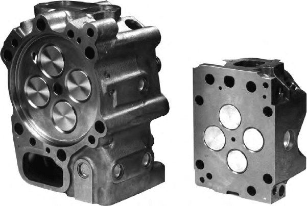
FigurE 30.25 the four-valve cylinder heads of mtu’s Series 2000 engine (right) and
Series 4000 engine (left) with central fuel injector