Woodyard D. (ed.) Pounders Marine diesel engines and Gas Turbines
Подождите немного. Документ загружается.

Early indication of necessary maintenance, based on the actual duty pro-
file, is provided by an electronic engine management system designed to foster
reduced downtime periods and lower servicing costs. A time-between-major-
overhauls of 18 000 h was anticipated by MTU.
uprated Series 4000 Engines
Four enhanced-power Series 4000 models developing 6 per cent to 10 per cent
more output than earlier versions were introduced in 2004 in response to the
demands of workboat and ferry operators. These V12- and V16-cylinder mod-
els benefited from extensive service experience with the original design, which
remained in the programme. Two V16 M61R and M61 models with respective
ratings of 1520 kW and 2000 kW were added to the range for workboat propul-
sion, while V12 and V16 M71 models were uprated to 1850 kW and 2465 kW
respectively for the ferry propulsion market.
Even higher power rises along with improved shock resistance, electromag-
netic compatibility and acoustic signatures were offered for Series 4000 mod-
els launched in 2006 for naval applications. These engines fulfil the strictest
military requirements, such as the latest NATO standards, and comply with US
EPA Tier II emission regulations. Output per cylinder was increased by over
26 per cent (from 170 kW to 215 kW) at a rated speed of 2170 rev/min. A V12-
cylinder model can thus deliver 2580 kW and a V16 model 3440 kW. In addi-
tion, the upper power limit of the Series 4000 programme was significantly
extended by the introduction, for the first time, of a V20-cylinder version offer-
ing outputs up to 4300 kW.
Advances in fuel injection, turbocharging and electronic management sys-
tems (all MTU in-house specialties) contributed to the higher performance and
lower emissions. A new generation common rail fuel injection system exploits
an HP in-line pump and LEAD injectors with individual fuel accumulators to
secure a virtually constant pressure of 1800 bar across the entire engine operat-
ing range. MTU’s latest generation ADEC (Advanced Diesel Engine Control)
electronic management system facilitates triple injection modes (pilot, main
and after-injection) which promote optimum control of the injection process
for low pollution, high-efficiency combustion.
Progress in own-design turbocharger development was also tapped. The new
engines are fitted with two turbochargers (V12- and 16-cylinder models) or four
turbochargers (for the V20-cylinder model) arranged in a single-stage sequen-
tial charging system, the turbochargers being switched-in or -out depending on
the engine speed.
niigata
The FX series from Niigata Engineering was completed in 1996 with a 205 mm
bore model to complement the established 165 mm and 260 mm high-speed
engines in a programme developed for fast commercial and military ves-
sel propulsion. The resulting 16FX, 20FX and 26FX models offer maximum
niigata 801
802 High-Speed Engines
continuous outputs from 1000 kW to 7200 kW in commercial service, with
slightly higher ratings available for naval propulsion. The 16FX engine is pro-
duced in in-line V8-, V12- and V16-cylinder versions running at 1950 rev/min,
the V20FX in V12 and V16 versions running at 1650 rev/min, and the V26FX
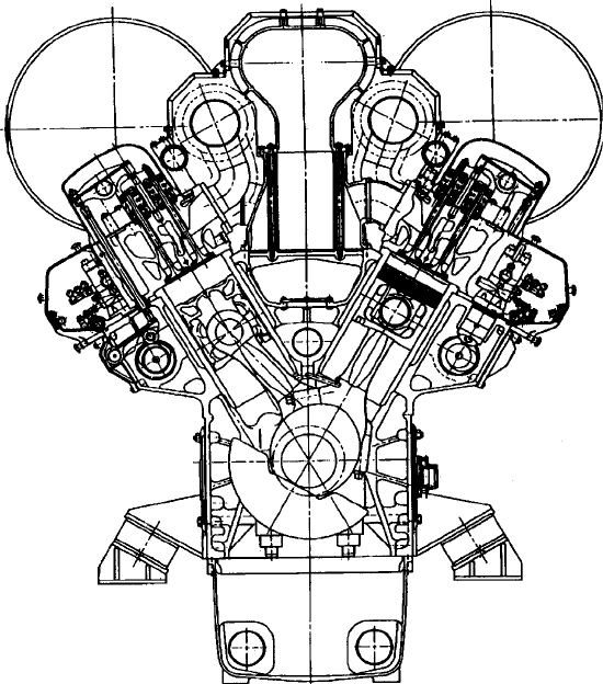
(Figure 30.26) in V12-, 16- and 18-cylinder versions running at 1300 rev/min.
Compact and highly rigid engines were sought by the Japanese designer
from a monobloc structure fabricated from nodular cast iron, with the exten-
sive use of light alloy elements contributing to a modest overall weight. Engine
width was minimized by adopting a V60° cylinder bank and overall length
reduced by minimizing the distance between cylinders while maintaining the
required bearing width.
A one-piece nodular cast iron piston was specified for the V16FX engine,
but the higher mechanical and thermal stresses imposed by the cylinder pres-
sure parameters of the V20FX ‘Blue Arrow’ engine influenced the selection
of a component with a steel crown and aluminium skirt for the larger design.
A bore cooling-type oil gallery structure on the crown reduces the temperature
of the piston at higher mean effective pressures. Higher cylinder pressures also
FigurE 30.26 Cross-section of niigata v26FX engine

foster increased piston blow-by, calling for a high sealing capability and wear
resistance from the piston rings. A chromium-ceramic coated top ring contrib-
utes to these properties, while an anti-polishing ring in the top of the cylinder
liner yields a lower lube oil consumption rate.
An output ceiling of 7200 kW at 1300 rev/min from the Niigata high-speed
engine portfolio is provided by the 18-cylinder version of the 260 mm bore
V26FX design. A monobloc frame of high-tensile strength ductile cast iron and
the use of light alloy parts where appropriate contribute to rigidity and light
weight from a compact envelope.
Niigata 16V20FX engine data
Bore
205 mm
Stroke 220 mm
Cylinders v16
output, mcr 4000 kW
Speed 1650 rev/min
mean piston speed 12.1 m/s
Specic fuel consumption 210 g/kW h
Weight 12 100 kg
Weight/power ratio 3.15 kg/kW
miller System for 32FX
The potential of the 32FX design was demonstrated by a development project
to create a lightweight, high-performance 320 mm bore medium-speed engine
series with a weight/power ratio of 4 kg/kW yielding outputs from around
8000 kW to 13 000 kW. Using the established 32CX engine as a basis, Niigata
reportedly achieved a rating of 769 kW/cylinder at 1030 rev/min from the 32FX
variant.
High output achieved by traditional development routes, Niigata explains,
is accompanied by an increase in mechanical load attributable to the higher
maximum pressure. Coping with the increased loading normally dictates the
specification of thicker and hence heavier components. Thermal loads also rise,
resulting in elevated NOx emissions. Reducing the compression ratio to main-
tain P
max
at a normal level, however, lowers efficiency and undermines overall
performance and starting capability.
Given these constraints, Niigata opted for the Miller system to keep the
P
max
and temperatures in the combustion chamber at a normal level, and reduce
NOx emissions, while increasing the brake mean effective pressure. The sys-
tem is designed to reduce charge-air temperature and pressure before compres-
sion (thus lowering the combustion temperature) by subjecting the charge air
in the cylinder to adiabatic expansion.
niigata 803
804 High-Speed Engines
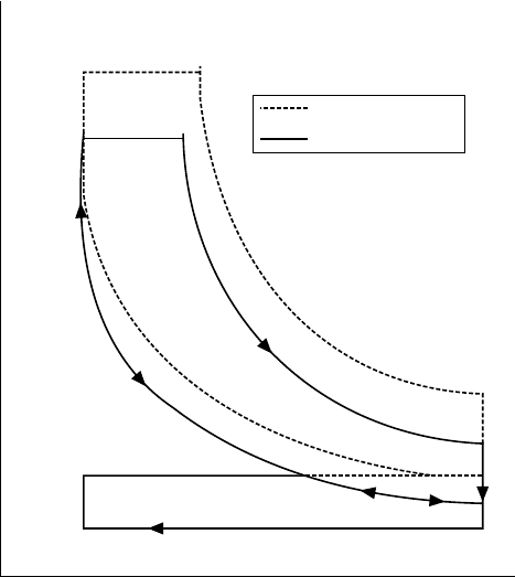
Miller systems come in two variants: an advanced closure timing, which
closes the intake valve before bottom dead centre; and a delayed closure tim-
ing, which closes the intake valve after BDC. Based on an engine performance
simulation analysis, Niigata selected the advanced closure timing route for the
6L32FX engine, adopting a closing timing of 10° before BDC in contrast to
the 35° after BDC applied in the 6L32CX engine (Figure 30.27).
In the Miller system, with the intake valve closed before BDC at the nor-
mal boost pressure, the exhaust temperature rises as the intake air volume is
reduced. This effect makes it necessary to increase the boost pressure to achieve
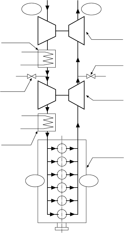
the targeted output, which lowers the exhaust temperature. Securing a higher
boost pressure than that obtainable with single-stage turbocharging called for
the adoption of a two-stage system in which the LP and HP turbochargers are
connected in series with two intervening air coolers (Figure 30.28).
Applying the Miller system in conjunction with two-stage turbocharg-
ing—LP and HP turbochargers connected in series with two intervening cool-
ers—secured the desired goal of a power rate of 38.2 (3.09 Mpa brake mean
effective pressure 12.4 m/s mean piston speed) at 110 per cent maximum
load—claimed to be the highest of any engine in the circa-320 mm bore class.
In addition, the NOx emission level with the Miller cam was 20 per cent lower
Conventional cam
Miller cam
Expansion
Exhaust
Volume V
Intake
Compression
Combustion
Pressuer P
FigurE 30.27 p–v diagram for miller system (niigata)
than with a conventional cam, equating to 5.8 g/kW h compared with the IMO
limit of 11.2 g/kWh at 1030 rev/min in E3 mode. Fuel consumption with a con-
ventional cam was lower than with the Miller cam at low loads (which could
anyway be improved by using a variable geometry cam) but it rose rapidly at
higher loads and exceeded the Miller cam at a load of around 75 per cent.
Supporting the performance boost, Niigata also investigated new materials
for key components to enhance engine reliability and reduce weight, notably:
a ceramic-sprayed bimetal cylinder liner; tri-alloy intake valves and pushrods;
and sodium-sealed and Waspaloy Inconel 718 exhaust valves. The ceramic-
sprayed coating was applied to the sliding part of the liner surface to improve
resistance to abrasion and seizure.
niigata 805
Intake
Exhaust
Low-stage
air cooler
Low-stage
turbocharger
Exhaust
bypass valve
High-stage
turbocharger
6L32FX test
engine
ExhaustIntake
High-stage
air cooler
Intake
bypass valve
FigurE 30.28 two-stage turbocharging system (niigata)

806 High-Speed Engines
paXman (man DiESEl)
Over 60 years experience in high-speed diesel design was exploited by Paxman
Diesels in creating the VP185 engine, launched in 1993 to join the UK-based
company’s established 160 mm bore Vega and 197 mm bore Valenta series
(Figure 30.29), which respectively offered specific outputs of 107 kW/cylinder
and 206 kW/cylinder. The new 185 mm bore design was introduced initially in
V12-cylinder form with outputs up to 2610 kW and complemented in 1998 by
a V18-cylinder version extending the power limit of the series to 4000 kW at
a maximum speed of 1950 rev/min. Paxman became a member of Germany’s
MAN B&W Diesel group (now MAN Diesel) in mid-2000, since when its pro-
gramme has ceased production.
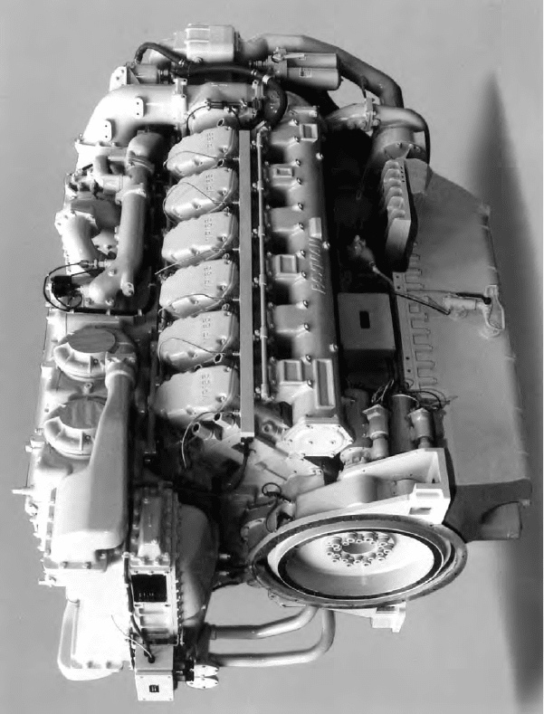
In designing the 12VP185 engine (Figure 30.30), Paxman sought improve-
ments in compactness and lightness over its earlier models, goals dictating a
smaller swept volume, slightly higher ratings and a review of piston speeds.
The first parameter to be fixed was the stroke which was set at 196 mm; this,
linked to a crankshaft speed of 1800 rev/min, gave a mean piston speed of
11.8 m/s for continuous duty. An improved speed platform for marine appli-
cations was derived, the edge of which is bounded by a maximum speed of
1950 rev/min with a mean piston speed of 12.8 m/s.
The cylinder bore was fixed at 185 mm which, coupled with a design
maximum mean effective pressure of 25.3 bar, delivered a maximum power of
FigurE 30.29 paxman v16-cylinder valenta engine
2610 kW at 1950 rev/min from the V12-cylinder configuration: a rating prima-
rily targeting high-speed military and commercial marine markets, as well as
mega-yacht propulsion. An unrestricted rating of 2180 kW at 1800 rev/min was
quoted (at 45°C air and 32°C sea water conditions) for continuous marine duties
(for example, fast ferry propulsion) where the engine’s high torque capability
over a broad speed range was considered especially attractive for hydrofoil
service.
The
18-cylinder VP185 model offers a maximum output of 4000 kW at
1950 rev/min, a 3300 kW continuous power rating for fast ferries and patrol
craft, and 3000 kW at 1770 rev/min for unrestricted marine duty.
paxman (man Diesel) 807
FigurE 30.30 paxman 12vp185 engine; note the compact turbocharging arrange-
ment along the top

808 High-Speed Engines
A smaller bore and stroke than the Valenta design, combined with a switch
from a 60° cylinder bank angle to a 90° configuration, achieved a layout which
was short and having a width under 1.5 m while providing an adequate plat-
form for the charge-air system mounted above the engine. The 90° bank angle
itself also lowered the profile of the charge-air system to foster space efficiency
(Figure 30.31).
FigurE 30.31 Cross-section of paxman vp185 engine
A higher mean effective pressure normally leads to a lower compres-
sion ratio which in turn promotes poor starting characteristics, reduced ther-
mal efficiency and possible exposure to ignition delay damage. Some of these
problems can be addressed by the use of inter-cylinder charge-air transfer
arrangements but Paxman decided to adopt a compression ratio in excess of
13:1. The resulting VP185 engine was claimed to be simple and easy to start
under cold conditions, with good thermal efficiency and the potential to satisfy
low NOx emission limits. The combination of high boost levels and compres-
sion ratios demands a robust construction but Paxman sought to avoid a heavy
and cumbersome engine by securing robustness within a small and hence a stiff
envelope.
The reciprocating assembly of the engine was designed for high strength
and rigidity in handling a high maximum cylinder pressure and securing high
reliability with a long lifetime. The backbone is a compact crankcase cast in
high-strength spheroidal graphite iron to provide a stiff and solid support for
the underslung crankshaft. Crankcase doors along each side of the engine
give access to the connecting rod large ends for in-situ servicing and piston
removal.
The crankshaft is a machined steel forging, fully nitrided to yield strength
and durability. It is secured by main bearing caps which are drawn internally
against the deep-fitting side faces of the crankcase by high-tensile set screws
and hydraulically tensioned main bearing studs. Such a configuration, the
designer asserted, delivered good strength and stiffness characteristics to the
bottom end of the crankcase and provided solid support for the crankshaft.
A generous overlap between the crankpin and main bearing journals added
to stiffness and strength. Both main and big end bearings are of steel-backed
aluminium–tin type with thrust washers controlling axial location. The crank-
shaft is provided with a viscous torsional damper totally enclosed within
the gearcase.
Connecting rods of side-by-side design are forged in high-tensile steel,
fully machined and ferritic nitro-carburized. The large end is obliquely split
to allow the rod to pass through the cylinder liner and the joint faces are ser-
rated. The one-piece nodular cast iron pistons incorporate a large oil-cooling
galley above the ring belt, oil being supplied by accurately aligned standing
jets mounted in the crankcase. The pistons run in wet cylinder liners made of
centrifugally cast high-grade iron.
The cast-iron cylinder heads are designed to withstand the high firing pres-
sures with an internal configuration ensuring maximum flame face stiffness and
high cooling efficiency. They incorporate two exhaust valves, two inlet valves
and a centrally mounted unit fuel injector (combined pump and injector) which
is fixed with a single screw. The valves and injectors are actuated through a
pushrod arrangement from a single large diameter camshaft mounted cen-
trally in the vee of the engine. The stiffness of the actuating system reportedly
achieves valve control similar to that of an overhead camshaft, while the spe-
cially designed unit injectors yield very high rates of fuel injection with clean
paxman (man Diesel) 809
810 High-Speed Engines
cut-off, contributing to low NOx generation and good fuel efficiency. The fuel
cam design was based on an optimized width for long life and a large base cir-
cle, coupled with high rates of lift to secure the key injection characteristics.
A maximum injection pressure of 1400 bar promotes good combustion
characteristics with low emissions and fuel consumption. The unit injector
is rack controlled, the rack itself being controlled by a linkage operated from
twin shafts in the centre vee of the engine. The shafts in turn are coupled to
the governor via an overspeed protection assembly which closes the fuel racks
independently of the governor in the event of the engine overspeeding.
A safety merit of the unit injector (which combines fuel pump and injec-
tor in one unit) is that it eliminated the need for HP fuel pipes. The LP fuel oil
is delivered to the injectors by a gear-driven lift pump mounted on the main
gearcase. The fuel is fed to a sub-assembly—comprising cooler, filter (duplex
optional), reservoir and solenoid-operated shut-off valve—mounted high at the
free end of the engine for convenient access.
A single camshaft reflects the policy adopted by the designers of minimizing
the number of components. This, allied to the 90° cylinder bank angle, allowed
the camshaft gear to mesh directly with the crankshaft gear and so eliminate the
need for idlers in a critical area and reduce the component count even further.
Charge air is delivered by a ‘valve-less’ two-stage turbocharging system
designed for simplicity and ease of maintenance. Preliminary explorations of
single-stage HP ratio turbocharging showed poor low-speed torque characteris-
tics due to surge limitation, along with poor acceleration and load acceptance.
Sequential turbocharging was considered but the necessary valve gear and asso-
ciated control system conflicted with the primary aim of keeping the engine
as simple as possible, Paxman explains. Another factor was that few turbo-
charger designs in the smaller size range were capable of meeting the pressure
ratio required.
A two-stage turbocharging arrangement with intercooling and aftercooling
was finally adopted for the VP185 engine, based on six Schwitzer automotive-
type turbochargers with broad and stable operating characteristics: four turbo-
chargers provide low-pressure charge air and two provide the HP air.
Inlet air compressed in the LP turbochargers is fed through a raw water inter-
cooler to the compressors of the HP turbochargers; HP air is then passed through
the jacket water aftercooler into the air manifolds on either side of the engine.
The HP stage exploits a pulsed exhaust system to give good low-end per-
formance without recourse to complex valve systems associated with sequen-
tially turbocharged configurations. The turbocharging system’s high air/fuel
ratios, coupled with HP/high rate fuel injection, address low NOx emission
requirements. A highly responsive performance with good engine torque char-
acteristics is reported throughout the speed range (Figure 30.32).
All six turbochargers are mounted in the walls of a water-cooled gas-tight
casing, the turbine sides arranged on the inside and the compressors on the out-
side. The rotating assembly and compressor casing of each turbocharger form
a cartridge which can be replaced quickly without the need for lifting gear