Torrieri D. Principles of Spread-Spectrum Communication Systems
Подождите немного. Документ загружается.

218
CHAPTER 4.
CODE SYNCHRONIZATION
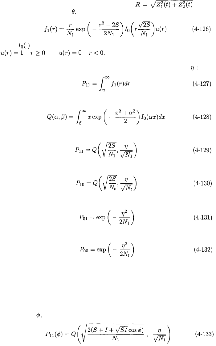
The probability density function of the envelope is ob-
tained by integration over The application of (1-59) gives
where is the modified Bessel function of the first kind and order zero, and
if and if
The detection probability for the threshold detector in the branch is the
probability that the envelope-detector output R exceeds the threshold
The Marcum Q-function is defined as
Applying this definition,
In the absence of noise interference, the detection probability is
If the acquisition tone is absent, but the noise interference is present, the false-
alarm probability is
In the absence of both the acquisition tone and the noise interference, the false-
alarm probability is
In (4-129) to (4-132), the first subscript is 1 when the acquisition tone is present
and 0 otherwise, whereas the second subscript is 1 when interference is present
and 0 otherwise.
Suppose that tone interference is present in a branch. We make the pes-
simistic assumption that this tone has a frequency exactly equal to that of the
acquisition tone, as indicted in (4-118). A trigonometric expansion of the in-
terference term and a derivation similar to that of (4-129) indicates that given
the value of the conditional detection probability is
4.5.
FREQUENCY-HOPPING PATTERNS
219
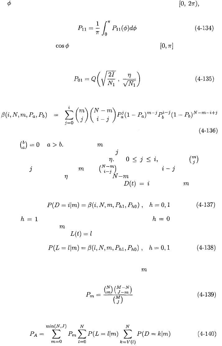
If is modeled as a random variable uniformly distributed over then
the detection probability is
where the fact that takes all its possible values over has been used
to shorten the integration interval. If the acquisition tone is absent, but the
tone interference is present, the false-alarm probability is
It is convenient to define the function
where if Given that of the N matched-filter branches receive
interference of equal power, let the index represent the number of interfered
channels with detector outputs above If there are ways
to choose channels out of and ways to choose channels with
detector outputs above from among the channels that are not interfered.
Therefore, the conditional probability that given that channels
receive interference is
where if the acquisition tones are present and if they are not.
Similarly, given that of N acquisition channels receive interference, the con-
ditional probability that is
If there are J interference signals randomly distributed among a hopset of
M
frequency channels, then the probability that out of N matched-filter
branches have interference is
The probability that acquisition is declared at a particular sampling time is
220
CHAPTER 4.
CODE SYNCHRONIZATION
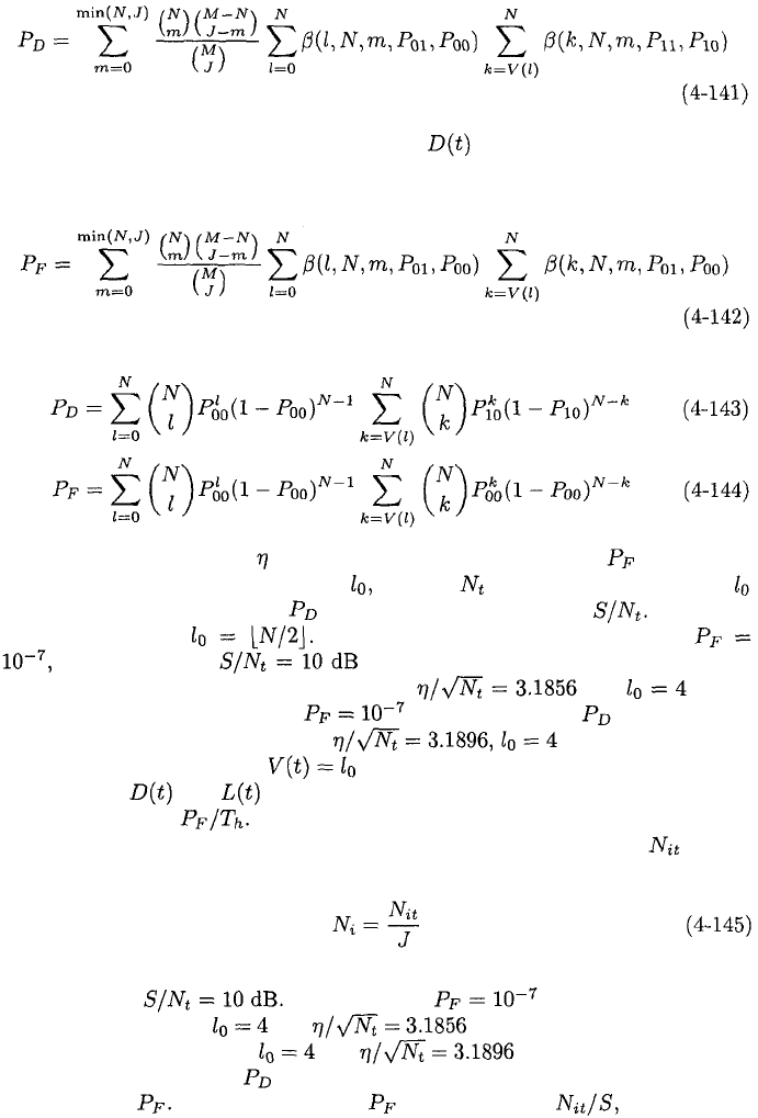
When the acquisition tones are received in succession, the probability of detec-
tion is determined from (4-137) to (4-140). The result is
For simplicity in evaluating the probability of a false alarm, we ignore the
sampling time preceding the peak value of in Figure 4.19 because this
probability is negligible at that time. Since the acquisition tones are absent,
the probability of a false alarm is
If there is no interference so that J = 0, then (4-141) and (4-142) reduce to
The channel threshold is selected to maintain a required when there
is no interference and the values of N, and are given. The value of
is then selected to maximize given the values of N and The best
choice is generally For example, suppose that N = 8,
and the SNR is when an acquisition tone is received. A
numerical evaluation of (4-144) then yields and as the
parameter values that maintain while maximizing in the absence
of interference. The threshold pair is the choice when a
fixed comparator threshold is used instead of the adaptive threshold
of (4-117). If and are sampled once every hop dwell interval, then the
false-alarm rate is
As an example, suppose that noise jamming with total power is uni-
formly distributed over J matched-filter frequency channels so that
is the power in each of these channels. Interference tones are absent and N =8,
M = 128, and To ensure that in the absence of jam-
ming, we assume that and when an adaptive comparator
threshold is used, and that and when a fixed comparator
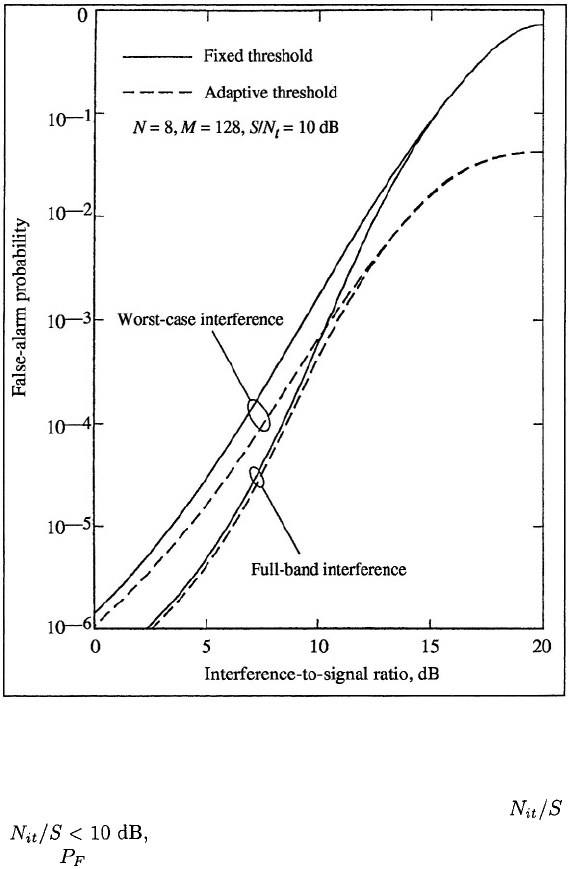
threshold is used. Since is relatively insensitive to J, its effect is assessed
by examining Figure 4.20 depicts as a function of the jamming-
to-signal ratio. The figure indicates that an adaptive threshold is much more
4.5.
FREQUENCY-HOPPING PATTERNS
221
Figure 4.20: False-alarm probability for matched-filter acquisition system.
resistant to partial-band jamming than a fixed threshold when is large.
When the worst-case partial-band jamming causes a consider-
ably higher than full-band jamming. It is found that multitone jamming
tends to produce fewer false alarms than noise jamming. Various other perfor-
mance and design issues and the impact of frequency-hopping interference are
addressed in [13].
Serial-Search Acquisition
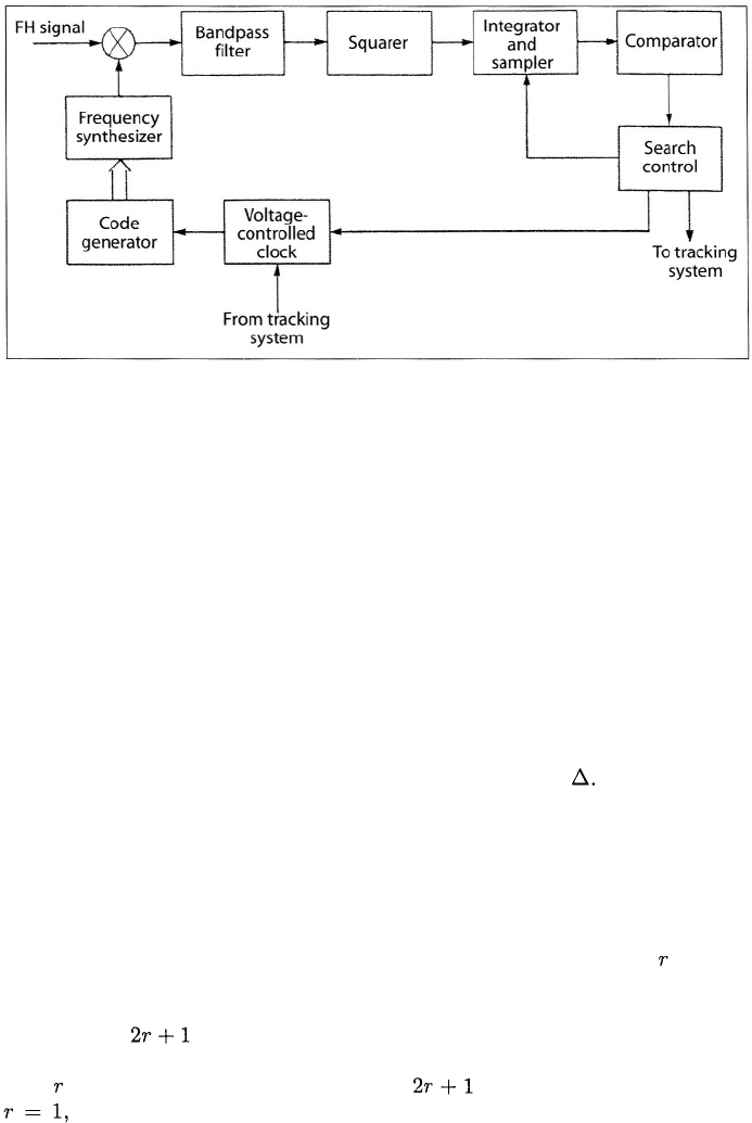
As illustrated by Figure 4.21, a serial-search acquisition system for frequency-
hopping signals determines acquisition by attempting to downconvert the re-
ceived frequency-hopping pattern to a fixed intermediate frequency, and then
comparing the output of an energy detector (Chapter 7) to a threshold. A
222
CHAPTER 4.
CODE SYNCHRONIZATION
Figure 4.21: Serial-search acquisition system.
trial alignment of the frequency-hopping pattern synthesized by the receiver
with the received pattern is called a cell. If a cell passes certain tests, acquisi-
tion is declared and the tracking system is activated. If not, the cell is rejected.
A new candidate cell is produced when the reference pattern synthesized by the
receiver is either advanced or delayed relative to the received pattern.
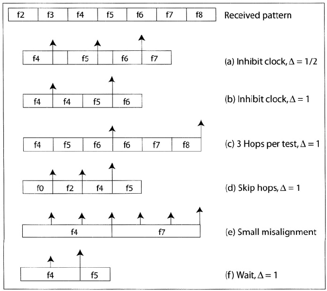
A number of search techniques are illustrated in Figure 4.22, which depicts
successive frequencies in the received pattern and six possible receiver-generated
patterns. Each search technique is implemented as part of a uniform or Z-search
of the timing uncertainty. The small arrows indicate test times at which cells
are rejected, and the large arrows indicate typical times at which acquisition
is declared or subsequent verification testing begins. The step size, which is
the separation in hop durations between cells, is denoted by Techniques (a)
and (b) entail inhibiting the code-generator clock after each unsuccessful test.
Technique (c) is the same as technique (b) but extends the test duration to 3
hops. Technique (d) advances the reference pattern by skipping frequencies
in the pattern after each unsuccessful test. The inhibiting or advancing of
techniques (a) to (d) or an alternation of them continues until acquisition is
declared. The small misalignment technique (e) is effective when there is a
high probability that the reference and received patterns are within hops of
each other, which usually is true immediately after the tracking system loses
lock. The code generator temporarily forces the reference signal to remain at a
frequency for
hop intervals extending both before and after the interval in
which the frequency would ordinarily be synthesized. If the misalignment is less
than hops, then acquisition occurs within hop durations. In the figure,
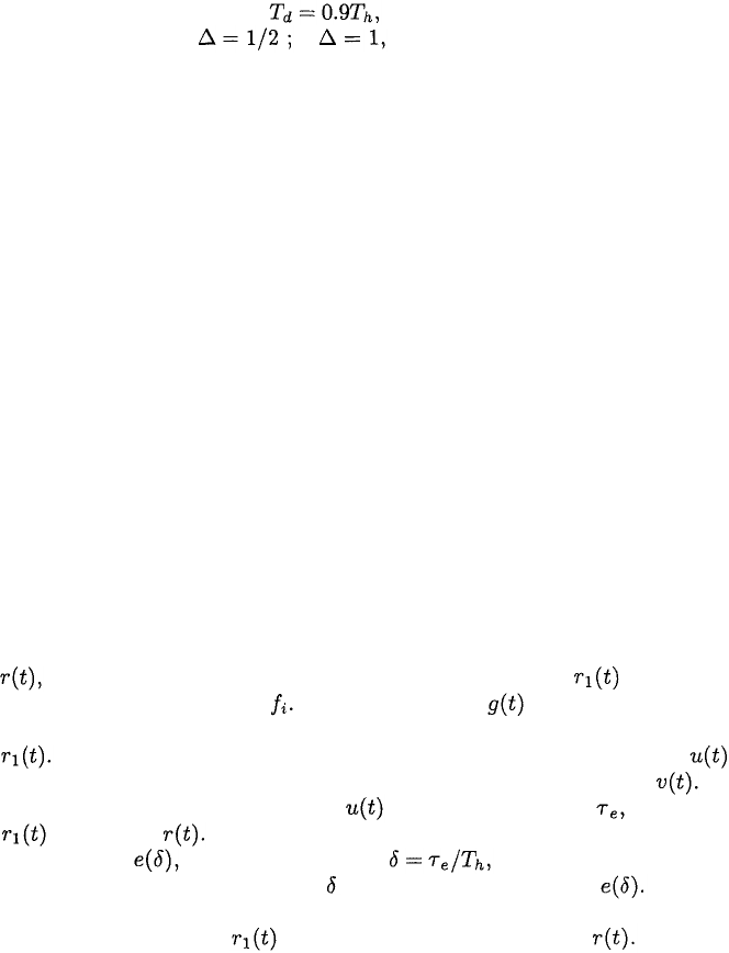
the initial misalignment is one-half hop duration, and it is assumed
that the first time the reference and received frequencies coincide, detection
fails, but the second time results in acquisition. Technique (f) entails waiting
at a fixed synchronization frequency until this frequency is received. This
4.5.
FREQUENCY-HOPPING PATTERNS
223
Figure 4.22: Search techniques for acquisition.
technique results in a rapid search if the reference frequency can be selected
so that it is soon reached by the received pattern. The reference frequency
is determined from an estimate of the timing uncertainty, the key bits, and
the TOD bits (Chapter 3), but must be periodically shifted by at least the
coherence bandwidth so that neither fading nor interference in any particular
frequency channel prevents acquisition.
When the period of the frequency-hopping pattern is large, special mea-
sures may be required to reduce the timing uncertainty. A reduced hopset
with a short pattern period may be used temporarily to reduce the timing un-
certainty and, hence, the acquisition time. A feedback signal from the receiver
may be used to adjust the timing of the transmitted pattern. In a network,
a separate communication channel or cueing frequency may provide the TOD
to subscribers. After detection of the TOD, a receiver might use the small
misalignment technique for acquisition.
The search control system determines the integration intervals, the thresh-
olds, and the logic of the tests to be conducted before acquisition is declared
and the tracking system is activated. The details of the search control strat-
224
CHAPTER 4.
CODE SYNCHRONIZATION
egy determine the statistics of the acquisition time. The control strategy is
usually a multiple-dwell strategy that uses an initial test to quickly eliminate
improbable cells. Subsequent tests are used for verification testing of cells that
pass the initial test. The multiple-dwell strategy may be a consecutive-count
strategy, in which a failed test causes a cell to be immediately rejected, or an
up-down strategy, in which a failed test causes a repetition of a previous test.
The up-down strategy is preferable when the interference or noise level is high
[14].
Since acquisition for frequency-hopping signals is analogous to acquisition
for direct-sequence signals, the statistical description of acquisition given in
Section 4.2 is applicable if the chips are interpreted as hops. Only the specific
equations of the detection and false-alarm probabilities are sometimes different.
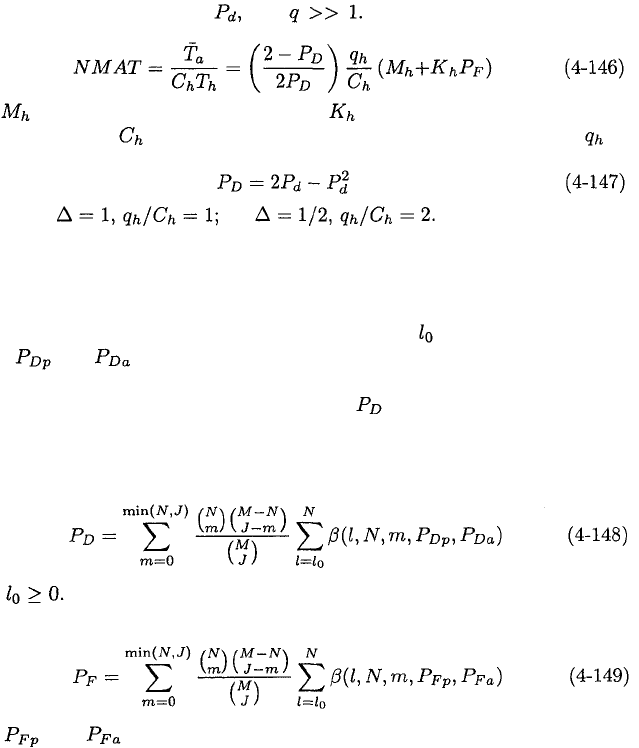
For example, consider a single-dwell system with a uniform search, a uniform a
priori correct-cell location distribution, two independent correct cells with the
common detection probability and In analogy with (4-93), the
NMAT is
where is the number of hops per test, is the number of hops in the
mean penalty time, is the number of hops in the timing uncertainty, is
the number of cells, and
For step size for
If the detector integration is over several hop intervals, strong interference
or deep fading over a single hop interval can cause a false alarm with high prob-
ability. This problem is mitigated by making a hard decision after integrating
over each hop interval. After N decisions, a test for acquisition is passed or
failed if the comparator threshold has been exceeded or more times out of
N. Let and denote the probabilities that the comparator threshold is
exceeded at the end of a hop interval when the correct cell is tested and inter-
ference is present and absent, respectively. Let denote the probability that
an acquisition test is passed when the correct cell is tested. If the N acquisition
tones in a test are distinct, then a derivation similar to the one for matched
filters yields
where Similarly, the probability that an acquisition test is passed when
an incorrect cell is tested and no acquisition tones are present is
where and are the probabilities that the threshold is exceeded when
an incorrect cell is tested and interference is present and absent, respectively.
4.5.
FREQUENCY-HOPPING PATTERNS
225
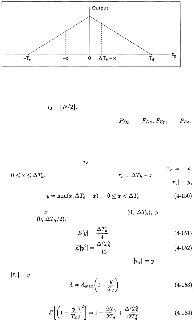
Figure 4.23: Amplitude of integrator output as function of relative pattern
delay.
A suitable choice for is Since the serial-search system of Figure 4.21
has an embedded radiometer, the performance analysis of the radiometer given
in Chapter 7 can be used to obtain expressions for and and
Although a large step size limits the number of incorrect cells that must
be tested before the correct cell is tested, it causes a loss in the average signal
energy in the integrator output of Figure 4.21 when a correct cell is tested. This
issue and the role of the hop dwell time are illustrated by Figure 4.23, which
depicts the idealized output for a single pulse of the received and reference
signals in the absence of noise. Let denote the delay of the reference pattern
relative to the received pattern. Suppose that one tested cell has
where and the next tested cell has following a cell
rejection. The largest amplitude of the integrator output occurs when
where
Assuming that is uniformly distributed over is uniformly
distributed over Therefore,
The correct cell is considered to be the one for which If the output
function approximates the triangular shape depicted in the figure, its amplitude
when is
Therefore, the average signal energy in the integrator output is
226
CHAPTER 4.
CODE SYNCHRONIZATION
which indicates the loss due to the misalignment of patterns when the correct
cell is tested. For example, if then (4-154) indicates that the average
loss is 1.26 dB when if then the loss is 2.62 dB.
The serial-search acquisition of frequency-hopping signals is faster than the
acquisition of direct-sequence signals because the hop duration is much greater
than a spreading-sequence chip duration for practical systems. Given the same
timing uncertainty, fewer cells have to be searched to acquire frequency-hopping
signals because each step covers a larger portion of the region.
Tracking System
The acquisition system ensures that the receiver-synthesized frequency-hopping
pattern is aligned in time with the received pattern to within a fraction of a hop
duration. The tracking system must provide a fine synchronization by reducing
the residual misalignment after acquisition. Although the delay-locked and tau-
dither loops used for the tracking of direct-sequence signals can be adapted to
frequency-hopping signals [17], the predominant form of tracking in frequency-
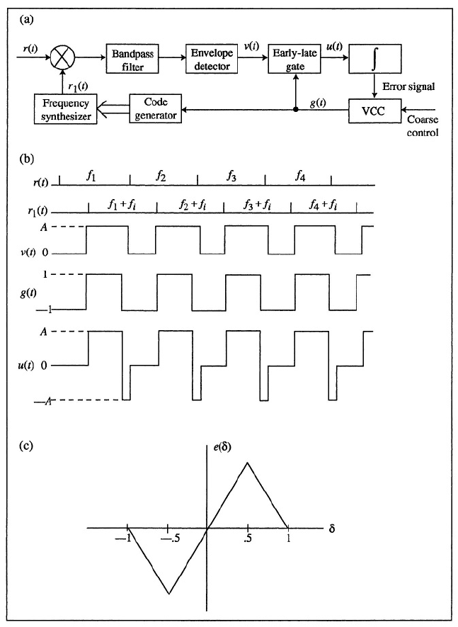
hopping systems is provided by the early-late-gate tracking loop [15]. This
loop is shown in Figure 4.24 along with the ideal associated waveforms for
a typical example in which there is a single carrier frequency during a hop
dwell interval. If the data modulation is MFSK, then the outputs of parallel
branches, each with a bandpass filter and envelope detector can be combined
and applied to the early-late gate. In the absence of noise, the envelope detector
produces a positive output only when the received frequency-hopping signal
and the receiver-generated frequency-hopping replica are offset by
the intermediate frequency The gating signal is a square-wave clock
signal with transitions from –1 to +1 that control the frequency transitions of
The early-late gate functions as a signal multiplier. Its output is
the product of the gating signal and the envelope-detector output The
error signal is the time integral of and is a function of the delay of
relative to The error signal can be expressed as the discriminator
characteristic which is a function of the normalized delay error.
For the typical waveforms shown, is positive, and hence so is Therefore,
the voltage-controlled clock (VCC) will increase the transition rate of the gating
signal, which will bring into better time-alignment with
If the tracking system loses lock and the small-misalignment test fails, then
the wait technique of Figure 4.22 can be used to expedite the reacquisition.
After dehopping the received signal to baseband, demodulating, and producing
oversampled information bits, the receiver establishes bit synchronization by
searching for a special sequence of marker bits that match a stored reference
sequence, as is often done for frame synchronization [16]. After this matching
occurs, information is extracted from subsequent bits. The information could
specify the time of occurrence and the spectral location of the next synchro-
nization frequency at which the receiver waits.
4.5.
FREQUENCY-HOPPING PATTERNS
227
Figure 4.24: Early-late gate tracking: (a) loop, (b) signals, and (c) discriminator
characteristic.