Tong W. Wind Power Generation and Wind Turbine Design
Подождите немного. Документ загружается.

Blade Materials, Testing Methods and Structural Design 425
All tests should be done in fl apwise direction towards both the downwind (suction)
and upwind (pressure) sides and in edgewise directions towards both the leading
and trailing edges. If it is important for the design, also a torsion test is needed
in order to determine the torsional stiffness distribution. The tests are undertaken
to obtain two separate types of information. One set of information relates to the
blade’s ability to resist the loads that the blade has been designed for. The second
set of information relates to blade properties, strains and defl ections arising from
the applied loads.
All tests in a given direction and in a given area of a blade shall be performed on
the same blade part. The fl ap- and edgewise sequence of testing may be performed
on two separate blades. However, if an area of the blade is critical due to the
combination of fl ap- and edgewise loading, then the entire test sequence shall be
performed on one blade.
3.3 Examples of full-scale tests used to determine deformation
and failure modes
In the following, the focus is on the ultimate strength of the rotor blades. Results
and fi ndings from recent full-scale tests to failure are studied.
A 25 m blade was tested to failure in three sections in the study by Sørensen
et al . [ 2 ]. The blade was loaded in the fl apwise direction. The purpose of the test
was to gain detailed information about failure mechanisms in a wind turbine blade
especially with focus on failures in the compression side (downwind side) of the
blade. Prior to the tests the blade was inspected by ultrasonic scanning to get an
overview if any imperfections and damages were present already before starting
the test. The supports and loading of the blade was changed during the test such
that it was possible to use the same blade in three tests, i.e. having independent
failures in three different sections of the blade. During each of the tests the behav-
ior of the blade was recorded by means of video and photos, strain gauges, acous-
tic emission and defl ection sensors. Two different types of defl ection sensors were
mounted on the blade, one giving the total defl ection of the blade and another
giving skin and main spar displacements, locally. The identifi ed failure modes are
presented in the next section (Section 4).
In a study by Jensen et al . [ 8 ], results from a full-scale test of a 34 m blade were
compared with fi nite element (FE) analysis. The blade was loaded to catastrophic
failure. Measurements supported by FE results show that detachment (delamina-
tion) of the outer skin from the box girder was the initial failure mechanism
followed by delamination of the load-carrying laminate, leading to collapse.
4 Failure modes of wind turbine blades
4.1 Defi nition of blade failure modes
Wind turbine blades can fail by a number of failure and damage modes. Obviously,
the details of damage evolution will differ from one blade design to another. How-
ever, experience shows that, irrespective of specifi c blade design, several types of
426 Wind Power Generation and Wind Turbine Design
material-related damage modes can develop in a blade. In some instances, these
damage modes can lead to blade failure or require blade repair or replacement.
It is useful to defi ne a few key concepts. The term failure is used here as a
broad term covering various processes that creates damage or cracking. Blade
failure indicates the critical state where the wind turbine blade loses its load-
carrying capability. Failure mode describes classifi cation of the macroscopic
types of failure which can occur. Defi ne damage as non-reversible processes that
occur as distributed phenomena (e.g. multiple matrix cracking or fi ber failure).
Damage modes is the term used to characterize specifi c types of damage at the
material scale. Fracture indicates damage in the form of macroscopic cracks.
Fracture modes indicate specifi c types of cracking (e.g. cracks between different
plies or cracks along interfaces between different materials). Crack initiation is
defi ned as the process of the formation of a sharp crack from a pre-existing fl aw.
The precise occurrence of crack initiation depends on microstructural details,
such as the size and distribution of porosity or other defects and the fracture
resistance of interfaces; all of these depend on the materials and processing
methods used. Crack propagation concerns the growth of sharp crack. Depend-
ing upon the crack size and load level, a crack may extend in a stable manner
(i.e. in small increments), or stop (crack arrest) or rapidly (unstable).
The load-carrying laminates in the blade aeroshell and box girder are made of
composite materials and adhesive joints that are damage tolerant. Damage tolerant
behavior implies that the fi rst mode of damage does not lead directly to failure, but
propagates in a stable manner and gives detectable changes so that the damage can
be detected before it reaches a critical size where it leads to failure. Therefore, failure
of wind turbine blades does not occur as a direct result of crack initiation along an
interface or by progressive damage to the fi bers and matrix. Rather, global failure of
a wind turbine blade involves the progression of several damage mechanisms that
can act in series or in parallel. This hierarchical failure evolution can be thought into
the blade design, creating a damage tolerant design. For example, interface debond-
ing along an adhesive joint can cause a detectable reduction in structural stiffness
while the redistribution of stresses causes corresponding higher cyclic strain ampli-
tudes in the blade or the initiation of cracks in laminates or sandwich structures in the
vicinity of the debond. However, global blade failure will not occur until a damage
type (typically a crack) reaches a critical size leading to unstable fracture.
4.2 Identifi ed blade failure modes
A considerable amount of knowledge is required to assess how damage devel-
ops in a wind turbine blade and to design a blade against failure using analytical
or numerical methods. Therefore, in order to validate the design, and to provide
insight into possible damage modes and their severity, blades are sometimes
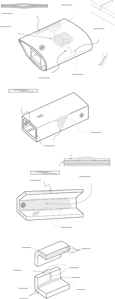
tested to failure by full-scale testing. Figure 5 shows sketches of the failure modes
( summarized in Table 1 ) found in a wind turbine blade tested to failure [ 2 ].
The consequences of the various damage and failure modes listed in Table 1
are widely different. For instance, cracking of the gelcoat fi lm is not as severe as
Blade Materials, Testing Methods and Structural Design 427
Figure 5: Sketches of observed failure modes in a wind turbine blade purposely
tested to failure [ 2 ]; damages in the aeroshell (top) and box girder
(below).
Type 2: Adhesive joint failure
Type 4:
Delamination
(+/-45°)
Type 2: Adhesive joint failure
Type 7: Cracks
in gelcoat
(chanal cracks)
Type 5: Splitting
along fibres
Type 1
:
Skin/adhesive
debonding
Type 3: Sandwich
debonding
Laminate
Foam
Type 4:
Delamination
Type 5:
Split
cracks
Type 5:
Split
cracks
Type 4: Delaminatio
n
Type 4
:
Compression
failure
Type 4:
Delamination
Type 4: Delaminatio
n
Type 4: Multipl
e
delaminations
Type 5
:
Split cracks in
surface layer
Type 5
:
Splitting
Type 5
:
Splitting
Type 4
:
Buckling-driven
delamination
Type 4: Compression failur
e

428 Wind Power Generation and Wind Turbine Design
Table 1: Failure modes and appropriate strength and fracture concepts used for
the design and analysis of wind turbine blades.
Basic damage modes Material property (static strength)
Adhesive joint failure
Crack in adhesive layer
G
Ic
(fracture energy)
Laminate/adhesive interface cracking
G
c
( y ) (interface fracture energy)
Interface cracking with fi ber bridging s ( d ) (cohesive law)
Sandwich failure
Interface cracking
G
c
( y ) (interface fracture energy)
Interface cracking with fi ber bridging s ( d ) (cohesive law)
Laminate failure
Tensile failure (fi ber fracture mode) –
damage zone
Lu
s
+
(tensile strength in fi ber direction)
Compressive failure (fi ber fracture
mode) – damage zone
Lu
s
−
(compressive strength in fi ber direction)
Tensile failure (matrix fracture
mode) – cracking
Tu
s
+
(tensile strength perpendicular to
fi bers)
Shear failure t
LTu
(shear strength)
Splitting crack (crack parallel with
fi ber direction)
G
c
( y ) (mixed mode fracture energy)
Delamination crack between plies
G
c
( y ) (interface fracture energy)
Gelcoat/skin delamination
Interface cracking
G
c
( y ) (interface fracture energy)
Interface cracking with fi ber bridging
s ( d ) (cohesive law), J
c
(work of separation)
Gelcoat cracking
Thin fi lm cracking
G
Ic
(fracture energy)
tensile failure (fi ber fracture) in a laminate. When the gelcoat cracks, the laminate
loses its protection against environmental exposure – which can lead to laminate
damage over a long time. In contrast, tensile failure in the form of fi ber fractures
decreases the stiffness and residual strength of the load-carrying laminates – this
can lead to rapid failure within a short period of time. Models and criteria for
assessing the various types of damages will be described in Section 7.
5 Material properties
5.1 Elastic properties
Modern wind turbine blades are three-dimensional structures made by the use
of several different materials and the elastic properties and thermal–physical con-
stants, such as thermal expansion coeffi cient, of materials infl uence the damage
developed in a blade. As a result, the stress fi eld depends on the elastic properties of
the materials used. For isotropic materials, the elastic properties are the Young's modu-
lus, E , and the Poisson's ratio, n . Orthotropic materials, such as composite laminates

Blade Materials, Testing Methods and Structural Design 429
with aligned continuous fi bers, have different elastic properties in different directions.
Therefore, the elastic properties must be related to a coordinate system. It is con-
venient to use a global x – y – z coordinate system (see Fig. 2 ) and a local coordinate
system that follows the direction of the fi bers. The longitudinal direction (the fi ber
direction) is assigned the subscript L, the (in-plane) direction perpendicular to
the longitudinal direction is called the transverse direction and given subscript
T, and the out-of-plane direction, orthogonal to the L and T directions is denoted
TT, i.e. T with a prime. Then, the elastic properties are specifi ed in terms of E
L
,
E
T
, E
T
′
, n
LT
, n
LT′
, n
TT′
, G
LT
, G
LT′
and G
TT
′
where E
i
denotes the Young's modulus
in the i -direction and n
ij
is the Poisson's ratio in direction j due to a normal stress
in the i -direction, and G
ij
is the shear modulus in the i – j -plane. Table 2 lists some
common materials used in wind turbine blades and their anisotropy classifi cation.
5.2 Strength and fracture toughness properties
Damage and failure modes are described by various parameters that may be stress-
based, energy-based or length-based (e.g. critical defect length). A damage mode
that involves a distributed damage zone is usually described in terms of a critical
stress value, i.e. by a maximum stress criterion (tensile or compressive strength).
Crack growth along a fracture plane is a localized phenomenon. The onset of crack
growth can be described in terms of a maximum stress intensity factor (fracture
toughness) or a maximum energy release rate (fracture energy). A crack experi-
encing fi ber bridging requires modeling of the bridging fi bers. This can be done by
a cohesive law (a traction-separation law). The area under the traction-separation
law is the work of separation. Table 1 lists parameters that are typically used to
characterize common damage and failure modes. These concepts are applicable
to static failure. A similar distinction can be made for cyclic damage evolution.
A complete analysis that would involve the design against the failure modes listed
in Table 1 will require the knowledge of all the relevant materials parameters.
A maximum stress criterion (or maximum strain criterion) can be used for mate-
rials that develop a damage zone (using appropriate safety factors, typically around
1.5–1.8). As an example, unidirectional fi ber composites, loaded in uniaxial ten-
sion in the fi ber direction, usually display a distributed damage zone during fail-
ure. Consequently, an appropriate strength measure is the tensile strength,
Lu
s
+
(here, subscript L indicates the longitudinal direction, subscript u indicates ulti-
mate strength and superscript + indicates tension). Other failure modes that are
usually characterized in terms of stress criteria are the compressive strength of
Table 2: Classifi cation of various materials used in wind turbine blades and the
anisotropy level used to characterize their elastic constants.
Isotropic materials Orthotropic materials
Adhesive Glass fi ber/polyester composites
Steel Carbon fi ber/epoxy composites
Polymer foam Wood (e.g. birch or balsa)
Gelcoat Bamboo
430 Wind Power Generation and Wind Turbine Design
fi ber composites loaded in the fi ber direction,
Lu
s
−
and the composite shear
strength, t
LTu
. As for elastic properties (Section 5.1) the strength properties of an
orthotropic material, such as a unidirectional fi ber composite, must be related to
specifi c directions. The longitudinal direction is assigned the subscript L, the
(in-plane) direction orthogonal to the longitudinal direction is called the transverse
direction and given subscript T. For a unidirectional fi ber composite, the tensile
strength in the fi ber direction,
Lu
s
+
, is usually much higher than the tensile strength
perpendicular to the fi ber direction,
Tu
s
+
.
Fracture by a single sharp crack is most often characterized by linear-elastic frac-
ture mechanics concept such as fracture toughness (the critical stress intensity fac-
tor) or equivalently the fracture energy (the critical energy release rate G
c
). The crack
opening is described in 3 pure opening modes: Pure normal opening (Mode I), pure
tangential crack opening/shearing (Mode II) and tearing (Mode III). The fracture
toughness and fracture energy are material constants but are infl uenced by tempera-
ture, loading rate and environmental conditions such as humidity level. In homoge-
nous materials, cracks tend to propagate under pure Mode I. Materials interfaces are
usually weaker than the surrounding materials; therefore cracks tend to remain at
interfaces. Therefore, the fracture energy, G
c
, of an interface between two dissimilar
materials is a function of the mode mixity y , where the mode mixity, y , is defi ned
from the complex stress intensity factor and a characteristic length scale, see [ 9 ] (in
isotropic materials, pure normal crack opening displacement corresponds to y = 0°,
whereas pure tangential opening corresponds to y = 90°). As noted earlier, the inter-
action of aerodynamic and gravity loading during blade rotation produces multiaxial
loading in wind turbine blades, which results in mixed mode loading of interfaces
and cracks. Thus, the fracture energy of interface cracks in wind turbine blades must
be measured for various load cases, corresponding to different mode mixities that
exist in a given cross section and along the blade length. This is the case for gelcoat/
laminate delamination, skin/core delamination, cracking along interfaces in adhe-
sive joints and delamination of laminates. Because fracture energy is a material con-
stant, it can be used for different geometries so long as the mode mixity is the same.
As discussed later, this simplifi es the testing requirements.
The energy required for crack initiation is less than the energy required for
crack propagation. Thus, the fracture energy of an interface is typically separated
into the energy required for initiation and the energy required for further crack
extension; however both values are strong functions of mode mixity.
As indicated in Fig. 5 , laminated fi ber composites can fail by delamination,
which is a cracking mode that can involve fi ber bridging between the crack faces .
If the fi ber composite develops a large scale fi ber bridging zone, it cannot be prop-
erly characterized by linear-elastic fracture mechanics. Instead, the mechanical
behavior of a large scale fracture process zone can be characterized by non-linear
fracture mechanics, in terms of the J integral [ 10 ] and a cohesive law [ 11 ]. A cohe-
sive law is the relationship between the local crack opening, d , and the local stress,
s , across the failure process zone. The cohesive stress is assumed to depend upon
the local crack opening only, s = s ( d ). The cohesive stresses can be normal and
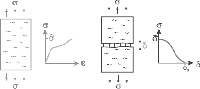
shear stresses (mixed mode cohesive laws). Figure 6 illustrates the concepts of
stress–strain and cohesive laws.
Blade Materials, Testing Methods and Structural Design 431
6 Materials testing methods
Because the cost of full-scale blade testing and certifi cation is signifi cant, various
laboratory tests are being developed to better access the structural reliability of com-
posite laminates and adhesive joints under conditions that simulate expected stress or
strain states in the turbine blade. In this section, test methods that can be used for the
measurement of relevant material properties are reviewed. The material properties
that infl uence the damage development in a wind turbine blade can be divided into
the elastic properties, the strength properties and fracture mechanics properties.
6.1 Test methods for strength determination
Different test methods are used for tensile and compressive strength determination.
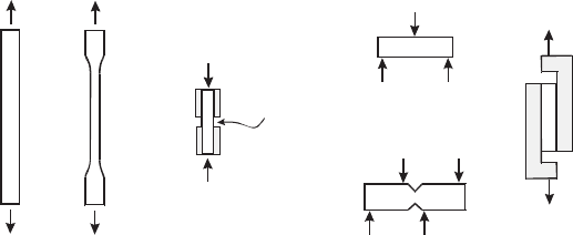
An overview of common test methods for strength measurements is given in Fig. 7 .
Tensile strength is determined by uniaxial tensile tests [ 12 , 13 ]. Tensile test speci-
mens are usually long, straight-sided or have a narrow gauge section (dog-bone shape)
to ensure that failure develops in the gauge section region where the stress fi eld is uni-
form. Bending tests can sometimes be used to estimate tensile strength [ 14 , 15 ]; but
bending failure can also occur by shear or compression failure and the failure mode
and test results must be carefully analyzed. Moreover, because of the non-linear stress
state developed in bending, the initiation of damage on one side of a specimen will
result in a shift of the neutral axis of the specimen which further complicates interpre-
tation of test results. Therefore, tensile tests which provide a uniform volume of stressed
material are preferred in order to avoid invalid determination of tensile strength.
Specimens for compressive failure are short in order to avoid buckling of the spec-
imen [ 16 ]. Unfortunately, the stress fi eld is not uniform in the specimens and
speci mens frequently fail away from the gauge section. In an effort to improve the
accuracy of compressive testing, various approaches have been developed to
reduce bending and transverse loading. In a test compressive test fi xture designed by
Bech et al . [ 17 ], hemispherical bearings are used to reduce transverse loading bend-
ing strains during compressive loading. The test fi xture provides more accurate
(a) (b)
Figure 6: Schematic illustration of (a) stress–strain behavior, which describes
the continuum response up to the peak stress,
ˆ
s
(onset of localization)
and (b) behavior after localization which is described in terms of a
traction-separation relationship called a cohesive law.
432 Wind Power Generation and Wind Turbine Design
(a)
(b)
(c)
(d)
Gauge
Section
(e)
Figure 7: Schematics illustration of test specimens for the determination of
strength data. (a) Specimens for determination of tensile strength
are usually straight-sided for unidirectional composites or dog-bone
shaped, (b) specimens for determination of compressive strength are
short to prevent global buckling, (c) shear strength of laminates can be
determined using the short-beam-shear test or (d) the V-notched beam
(Iosipescu) test. For sandwich structures, rail shear testing is typically
utilized for shear strength measurements (e).
measurements of compressive stress–strain behavior for both monotonic and
fatigue loading of composites.
The shear strength of composite laminates can be measured by the use of a short
beam subjected to three-point bending [ 18 ] or by the Iosipescu shear test [ 19 ].
Again, the test results must be carefully analyzed and the failure mode documented
since tensile failure can occur prior to shear failure for laminates that possess a
high shear strength. For sandwich structures, shear testing is commonly performed
using a rail shear approach [ 20 ].
6.2 Test methods for determination of fracture mechanics properties
Fracture properties are determined from tests of specimens having an artifi cial
crack in the form of a pre-cut notch or a thin slip foil (e.g. by use of Tefl on between
interfaces) introduced during specimen manufacture. However, a machined or arti-
fi cial notch is not as sharp as a real crack. Thus, as discussed later, test methods
that allow the initiation and arrest of cracking are preferred, since they enable
the fracture properties to be determined from a truly sharp crack. An overview
of commonly used specimen geometries for fracture mechanics-based testing of
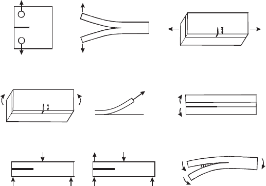
composite interfaces is given in Fig. 8 .
First, methods for determination of the fracture energy of elastically isotropic
materials are reviewed. The Mode I (pure normal opening) fracture properties of
isotropic materials are often determined from the compact tension (CT) specimen.
For thin (isotropic and orthotropic) laminated structures manufactured with the same
material layers, such as composites and sandwich structures, double cantilever beam
(DCB) specimens loaded with wedge forces are commonly employed, both for static
and cyclic crack growth [ 21 ]. For both these specimens the energy release rate depends
Blade Materials, Testing Methods and Structural Design 433
on the crack length; for the determination of the energy release rate, the crack length
must thus be measured experimentally and correlated with the applied force.
To determine the Mode II fracture energy of composites (pure tangential crack
opening displacements) the end-notched specimen (ENS) is commonly used [ 22 ].
The ENS specimen is loaded by compressive forces; part of the applied force is
transmitted from one beam to the other by contact between the beams. However, this
method does not provide stable crack growth, so the value of the fracture energy may
be overestimated due to crack initiation and due to friction between the crack faces.
A mixed mode bending (MMB) specimen, also loaded by transverse forces, was
proposed by Reeder and Crews [ 23 ]. The MMB specimen allows the entire range
of mode mixities, from pure mode I to pure mode II, for the same specimen geom-
etry. The energy release rate depends on the crack length. For Mode II dominated
loading the crack propagation can be unstable. As shown in Fig. 8 , another
approach is to load DCB specimens with uneven bending moments (DCB-UBM)
[ 24 , 25 ]. For the DCB-UBM specimen confi guration, the energy release rate is
independent of crack length and stable crack growth occurs for all mode mixities
making the specimen well suited for measuring the interface fracture behavior of
various materials, including laminates and sandwich structures.
For large-scale bridging problems, such as cracking with cross-over bridging, it
is of relevance to determine cohesive laws which can be used to describe the
mechanical response of the bridging zone and thus represents large-scale bridging
(a)
P
P
P
P
P
1
P
3
P
(b)
P
P
a
(c)
M
M
a
(d)
(e)
(f)
M
M
P
M
1
M
2
M+M
12
P/2 P
2
P
4
P/2
(g)
(h)
(i)
Figure 8: Overview of fracture mechanics test methods: (a) CT specimen, (b)
DCB specimen loaded by wedge forces, (c) thin fi lm on a substrate
loaded in tension or bending (d), (e) the peel test; (f) DCB sandwich
specimens loaded with pure bending moments, (g) the end lap shear
(ENS), (h) the MMB specimen, and (i) the DCB loaded with uneven
bending moments (DCB-UBM).
434 Wind Power Generation and Wind Turbine Design
in models. Few direct measurement methods exist. For pure mode I, the cohesive
law can be determined by direct tension tests [ 26 ]. Another method is to determine
the bridging stresses from the crack opening profi le [ 27 ]. Yet another method is to
derive the bridging law from the J integral [ 28 ]. In that respect a DCB specimen
loaded with pure bending moments is preferred [ 29 ], since the J integral can be
expressed in closed analytical form [ 11 ].
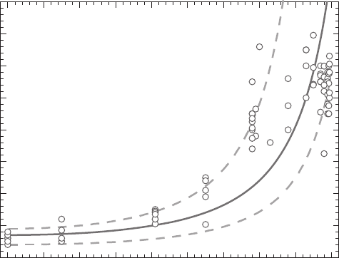
Figure 9 shows a typical example of the dependency of the fracture energy on
mode mixity for a unidirectional glass fi ber composite laminate; the testing was
conducted using the DCB-UBM specimen [ 30 ]. The initiation fracture energy
increases signifi cantly with increasing mode mixity (increasing amount of tangential
crack opening displacement).
Very few studies address the determination of mixed mode cohesive laws. In
some studies, only pure mode I and mode II cohesive laws are determined from
pure mode I and mode II tests and treat them as independent cohesive laws [ 31 ,
32 ]. A more recent approach is to obtain mixed mode cohesive laws from results
of a DCB-UBM specimen. For this specimen and loading confi guration, the J
integral is obtained in closed form even in the case of large-scale bridging. With
the closed-form solution for the J integral, cohesive laws can be obtained by partial
differentiation of the J integral with respect to the end-opening and end-sliding
displacements of the crack [ 30 , 33 ].
0 102030405060708090
0
200
400
600
800
1000
1200
1400
1600
Initial Fracture Toughness, J
0
(J/m
2
)
Mode Mixity, ψ (degrees)
Figure 9: Initial interface fracture energy as a function of mode mixity for
interlaminar cracking of a unidirectional glass fi ber/polyester composite
[ 30 ]. A mode mixity of 0° corresponds to a crack opening displacement
normal to the cracking plane and a mode mixity of 90° corresponds to
tangential crack opening displacements.
