Tong W. Wind Power Generation and Wind Turbine Design
Подождите немного. Документ загружается.

Blade Materials, Testing Methods and Structural Design 435
Testing of thin surface layers, such as gelcoats on wind turbine blades, offers
special challenges, since standard fracture mechanics test methods cannot be
applied. The determination of the fracture energy of a gelcoat can be determined
by tensile [ 34 ] or bending experiments based on the concept of steady-state crack-
ing of a channeling crack [ 35 , 36 ]. The peel test can be used for measuring the
fracture energy of the interfaced between a gelcoat and a substrate [ 37 ]; however,
large-scale plasticity in the gelcoat may lead to erroneous results if this is not
accounted for [ 38 ]. Alternatively, a DCB sandwich specimen can be made by
bonding an additional beam onto the gelcoat attached to a substrate.
6.3 Failure under cyclic loads
Test methods used under static loads can in many cases also be used for the study of
fatigue damage evolution. In some cases, however, special requirements mean that spe-
cial concerns have to be accounted for in the selection of test specimens. Moreover, the
data collection, the data analysis and materials properties used for describing fatigue
are different from those used to describe strength properties under static loading.
Under cyclic loading, it is useful to distinguish between failure due to a damage
zone and failure due to crack growth. For materials that fail by a damage zone,
such as a unidirectional fi ber reinforced composite loaded in the fi ber direction,
the life under cyclic loading can be described by a so-called S–N curve, which is
the relationship between the maximum applied stress, s
max
, and the number of
cycles to failure, N
f
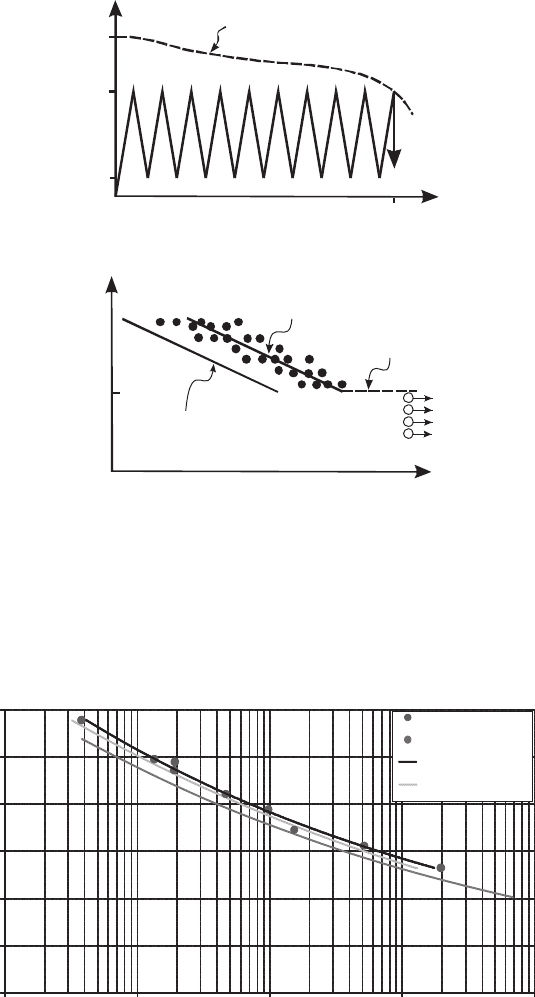
. A schematics of an S–N curve is given in Fig. 10 . The applica-
tion of S–N data in design is straightforward. For example, assume that a compo-
nent should be designed such that it safely survives a given number of load cycles.
Then, from the S–N curve one reads off the maximum applied stress, s
max
, corre-
sponding to that number of cycles. The S–N curve depends on the minimum applied
stress, s
min
; usually expressed in terms of the R -ratio, which is R = s
min
/ s
max
. The
approach can refi ned to predict for a small fraction, say 1/1000 of failed specimens
(instead of the average fatigue life) and to account for different maximum load
(load spectrums), e.g. by the use of the Palmer-Miners rule [ 39 ].
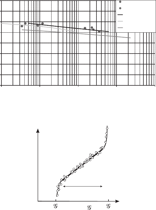
S–N curves for tension–tension and compression–compression testing of
glass-epoxy unidirectional laminates for the spar beam for wind turbine blades are
shown in Figs 11 and 12 . The data are from the Optidat database [ 40 ]. The mea-
sured fatigue data are evaluated according to ASTM E739, and the 50% median
line and the lower 95% confi dence limit are shown in these diagrams. The statisti-
cal 95% lower confi dence limits based on the 95% survival line for the Siemens
Wind Power shell materials is also shown in the fi gure. This analysis is based on
the work by DNV [ 41 ]. The fatigue lifetime depends on both the applied amplitude
and the applied mean value and can be presented in other useful graphs [ 42 ].
Of particular importance is whether or not an endurance fatigue limit exists for a
material. A fatigue limit implies that a stress limit exists, such that if the material is
never loaded beyond this value,
fl
s , then the material will never fail due to fatigue.
In addition to buckling and failure due to static overload, perhaps the most
important mode of damage that needs to be addressed in design is the cyclic growth
436 Wind Power Generation and Wind Turbine Design
0.00
0.20
0.40
0.60
0.80
1.00
1.20
1000 10000 100000 1000000 10000000
Maximum Strain (%)
Number of cycles to faliure
Sample: Optimat, UD2, R=0.1, Fatigue test
R = 0.10
R = 0.10 run out
Power (S independent)
Lower 95% confi.
Figure 11: S–N curve for tension–tension fatigue of a glass fi ber/epoxy composite [ 40 ].
(a)
Residual
Strength
Fatigue
Failure
Number of Cycles, N
σ
max
σ
min
σ
u
Applied Stress
N
f
(b)
σ
fl
Run-out
Number of Cycles to Failure, N
f
Maximum Applied Stress,
σ
max
Fatigue
Limit
Design
line
Average
Figure 10: Description of fatigue of materials experiencing damage. (a) The num-
ber of cycles to failure, N
f
, is determined by cycling specimens to a pre-
selected maximum stress, s
max
. (b) A schematics of an S–N curve,
which is the relationship between the maximum applied stress and the
number of cycled to failure.
Blade Materials, Testing Methods and Structural Design 437
0.00
0.20
0.40
0.60
0.80
1.00
1.20
1.40
1.60
1000 10000 100000 1000000 10000000
Maximum Strain (%)
Number of cycles to faliure
Sample: Optimat, UD2, R=10, Fatigue test
R = 0.10
R = 0.10 run out
Power (S independent)
Lower 95% confi.
95%/95% -line
Figure 12: S–N curve for compression–compression fatigue of a glass fi ber/epoxy
composite [ 40 ].
log(Δ )
th
Ic
log(da/dN)
Paris-Erdogan
Regime
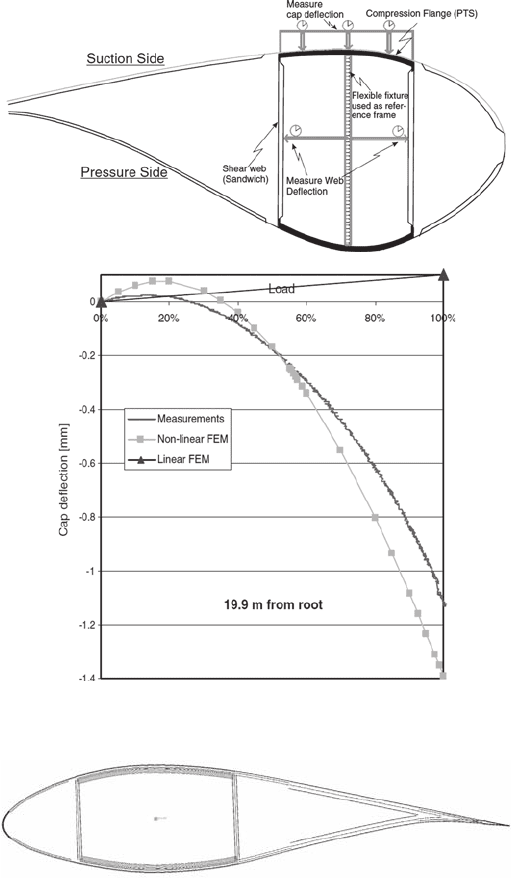
Figure 13: Schematics of a typical relationship between cyclic crack growth rate
(d a /d N ) and maximum applied energy release rate, G
max
for cyclic
crack growth. A threshold value, G
t
h
, often exists, below which no
crack growth is assumed to occur. As G
max
approaches the fracture
energy, G
Ic
, the crack growth rate increases asymptotically. In between
these regimes, the crack growth rate can be described in terms of the
Paris-Erdogan relationship.
rate of cracks along laminate and adhesive interfaces. If an interface is not prop-
erly designed for damage tolerance, even small initial cracks could potentially
grow to a critical size over the 20-year design life of a wind turbine blade. For
materials or interfaces containing cracks, the cyclic crack growth rate, d a /d N , can
be measured as a function of the applied energy release rate. Figure 13 shows a

438 Wind Power Generation and Wind Turbine Design
schematic drawing of typical material behavior. For most materials, a threshold,
G
th
, exists, below which no crack growth occurs. For G
max
> G
th
, crack grow
occurs, but the rate depends on Δ G = G
max
− G
min
, where G
min
is the minimum
cyclic applied energy release rate. For G
max
increasing close to G
Ic
(the fracture
energy), the crack growth rate increases rapidly. For intermediate values of Δ G the
crack growth rate can be described in terms of the Paris-Erdogan relation [ 43 ]. For
Mode I cracking, the Paris-Erdogan relation can be written as [ 44 ]:
d
()
d
n
a
AG
N
=Δ
( 1 )
where a is the crack size, N is the number of cycles, A and n are the fi tting param-
eters. The crack growth rate, d a /d N can be understood as the crack extension per
load cycle and has the units mm/cycle.
As an example, results from cyclic crack growth experiments are shown in Fig. 14
[ 44 ]. The results are obtained from tests of DCB specimens loaded with wedge
forces under constant load amplitudes. For this specimen confi guration, the range
of the energy release rate increases with increasing crack length. Thus, a single test
gives data for the crack growth rate under various values of Δ G . A curve-fi t, based
on the Paris-Erdogan relation (1), is shown as a solid line in the fi gure.
For materials experiencing large-scale bridging under cyclic crack growth, the
situation is more complicated. As the crack tip advances, a large-scale bridging
zone develops. The bridging stresses restrain the crack opening, leading to a
decreasing crack growth rate [ 45 ]. However, the cohesive laws that operate under
cyclic loading are likely to be different from those present under monotonic crack
opening. Thus, the cohesive laws should be characterized as a function of the num-
ber of cycles. Precisely how this should be done is not quite clear, although a few
ideas have been developed [ 45– 47 ].
Mode I
da/dN = 2.16 × 10 × (
Δ
)
–11 1.49
10
-3
10
-4
10
-5
10
-6
10
1
10
2
10
3
Δ
I
(J/m )
2
da/dN (mm/cycle)
Figure 14: The crack growth rate, d a /d N , is shown as a function of the energy release
rate range, Δ G , for a unidirectional glass fi ber/epoxy composite [ 44 ].
Blade Materials, Testing Methods and Structural Design 439
7 Modeling of wind turbine blades
7.1 Modeling of structural behavior of wind turbine blades
7.1.1 Modeling of entire wind turbine blade
This section outlines basic rules for structural design of wind turbine blades.
A more thorough description of the overall design of wind turbines for various
onshore and offshore applications can be found in the DNV/Risø guidelines [ 48 ]
and in other chapters of this book.
Some designs are constructed with a load-carrying box girder (main spar) that
supports the outer aeroshell as shown in Fig. 2 , which illustrates a typical struc-
tural layout for a wind turbine blade with a load-carrying girder. The purpose of
the box girder is to give the blade suffi cient strength and stiffness, both globally
and locally. Globally, the blade should be suffi ciently stiff in order not to collide
with the tower under all types of loading. Locally, the webs, together with the stiffness
of the outer shell, ensure that the shape of the aerodynamic profi le is maintained.
The box girder or the webs usually extend from the root of the blade to a position
close to the tip. The load-carrying fl ange of the box girder, sometimes called the cap,
is usually a single skin construction (i.e. consisting of a single thick laminate, with
most of the fi bers aligned along the blade length, i.e. the z -direction, see Fig. 2 ). The
webs are usually quite thin sandwich structures; the main purpose of these is to take
the shear loads of the blade. The proper design of the blade requires careful analysis.
For example, geometrical non-linear effects can result in higher than expected loading
of the webs which may result in blade failure at a stress level that is much lower than
predicted when the design is based on linear calculations. The design should ensure
that the failure criteria discussed in the previous section are not exceeded anywhere in
the blade during regular and extreme load situations. This section presents an
overview of modeling tools used to predict the static and dynamic behavior of wind
turbine blades and to determine the stress and strain distribution within a blade.
7.1.2 Beam models
The global defl ection of wind turbine blades, Eigen frequencies and other global
behavior can in general be analyzed with good accuracy by use of beam models.
However, if greater accuracy is needed or more locally structural phenomena need
to be analyzed, more detailed shell and/or solid FE models must be used.
The idea of a beam model is to describe the cross section properties in terms of
suitable coeffi cients, such as area, moment of inertia, torsional stiffness, etc. The
behavior of the beam is then described entirely in terms of one-dimensional func-
tions, such as axial and transverse displacement and torsion. In order for such a
theory to give an accurate representation of the actual behavior of a wind turbine
blade, it is important that the description of the cross section parameters contain all
the relevant information. This includes stiffness parameters, the center of mass, the
elastic center and the center of torsion. For a typical wind turbine blade these three
centers will be located fairly close to each other, but are not coincident.
While the basic properties of cylindrical beams date back to the late 19th century,
consistent theories accounting for cross section variation, pre-twist of the blade
440 Wind Power Generation and Wind Turbine Design
and material anisotropy are much more recent and theories describing these fea-
tures are not yet fully developed.
An important non-linear large-defl ection effect is called the Brazier effect [ 49 ].
The Brazier effect is a non-linear effect resulting from curvature when bending a
beam or a slender structure. Because of the curvature the longitudinal compressive
and tensile stresses result in transverse stresses towards the neutral plane of the
beam. This causes fl attening of a hollow cylinder or suck-in deformation or a
hollow box. This then result in reduction of the bending stiffness of the section.
A fully consistent representation including the three centers has been given
e.g. by Krenk and co-workers [ 50– 52 ]. This theory incorporates the effect of pre-
twist in the form a geometric coupling of extension and twist [ 52 ]. A numerical
procedure was developed for the parameters of a moderately thin-walled cell cross
section often used for wind turbine blades [ 53 ]. A further development of these
principles has been carried out later under the name of Variational Asymptotical
Beam Section Analysis (VABS) by Hodges [ 54 ]. In this method, a beam with arbitrary
cross sections consisting of different materials can be analyzed by a one-dimensional
beam theory. The method provides a simply way to characterize strain in an initial
curved and twisted beam and all components of cross sectional strain and stress can be
accurately recovered from the one-dimensional beam analysis.
7.1.3 FE models
In FE analysis a structure is modeled with a fi nite number of discrete elements
represented by some element nodes in which the elements are connected. Because
of the blade size, and lack of symmetry, most published research on wind turbine
blade design using FE analysis is done using relatively coarse meshes.
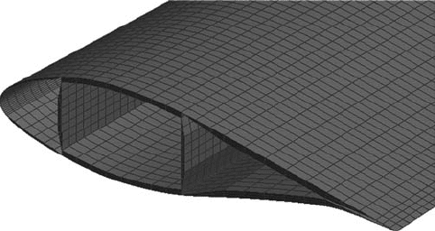
A comparison between a geometrically non-linear FE analysis and full-scale
blade testing has been investigated by Jensen et al . [ 8 ]. In their experiments, a 34 m
glass fi ber PMC blade was statically loaded to catastrophic failure. Strong non-
linearities in various blade responses were found. The Brazier effect was found to
dominate in the inner part of the blade. The relative defl ection of the box girder cap
was measured during the experiments and compared with linear and non-linear FE
analysis (see Fig. 15 ). The linear analysis was not capable of predicting these relative
cap defl ections, in particular at high loads. The non-linear analysis provided reason-
able agreement with experimental measurements. It is clear from this that non-linear
FE analysis is required for certain aspects of blade design.
The most common types of FE models used for the structural design of wind
turbine blades are:
Outer surface shell model – using shell element offset •
Mid-thickness shell model •
Combined shell/solid model •
The application of these various models is described below.
The outer surface model of a blade is a shell model based on shell elements that are
located on the physical outer surface of the aerodynamic shell. This approach is conve-
nient since the outer surface is often specifi ed from aerodynamical purposes. The
material is then offset inwards in order to locate it at the correct physical position,
Blade Materials, Testing Methods and Structural Design 441
Figure 15: Measured relative defl ection of the box girder cap compared with linear
and non-linear FE analysis [ 8 ].
Figure 16: Outer surface shell FE model with material offset inwards from the
outer surface.
see Fig. 16 . This type of model is typically used for the practical design of wind
turbine blades today.
The mid-thickness model is also created from the geometry of the aerodynamic
shell. However, here the shell elements are located at the mid-plane for the different
parts of the cross section. The different material thicknesses in the cross section
imply that the FE shell will not have a continuous surface like the outer surface
442 Wind Power Generation and Wind Turbine Design
model. The discontinuous surfaces are connected by rigid (fi xed) elements. These
rigid elements are capable of transferring all displacements and rotations from one
node to another without deforming.
The combined shell/solid model is a combined shell/solid model constructed
based on the following surfaces representing the blade section:
Outer aerodynamic surface (outer sandwich skins) •
Inner sandwich skins in the leading and trailing part of the blade •
Leading and trailing edge •
Web sandwich skins •
Box girder caps •
After creating the surfaces, the solids are then created from two opposing surfaces.
The solids represent the following:
Sandwich core in the leading and trailing part of the blade •
Sandwich core in the webs •
Adhesive bonds between the aerodynamic shell and the spar •
Layered shell elements are then used to represent the composite laminates on both
sides of the solids. An example is shown in Fig. 17 . The combined shell/solid
model provides the highest degree of accuracy.
7.1.4 Limitations with shell models
A number of studies have shown that there is limited correlation between the
torsional response obtained by numerical structural models and measurements.
Madsen [ 55 ] compared the responses of a beam model and a shell FE model.
Poor correlation was found for predictions of torsional Eigen frequency and Eigen
mode. Larsen [ 56 ] compared the response of the numerical models from Madsen
[ 55 ] with a number of measured modal modes; the correlation related to torsional
response was limited especially for the higher torsional modes. In predicting tor-
sional behavior, problems associated with the use of offset nodes for layered shell
elements in FE analysis has also been reported by Laird et al . [ 57 ].
Figure 17: Meshed part of shell/solid FE model. Solid elements are used for sand-
wich cores and for the adhesive connection between the box girder and the
aerodynamic shell. Shell elements are used for the other structural part.
Blade Materials, Testing Methods and Structural Design 443
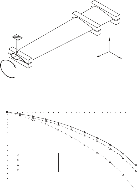
Branner et al . [ 58 ] recently investigated how well different FE modeling
techniques can predict bending and torsion behavior of a wind turbine blade. The
results from the numerical investigations were directly compared with measure-
ments obtained from experimental testing of a section of a full-scale wind turbine
blade. Torsional testing was performed by locking the tip cross section in a point
directly over the center of the box girder (see Fig. 18 ). This point is fi xed, but the
cross section can rotate around the z -axis and translate in the horizontal ( x – z ) plane,
since the vertical bar, indicated in Fig. 18 , is able to rotate in both ends. The move-
ment in the horizontal plane is not entirely free since the movement is restricted to a
circular arc. The numerical and experimental results are in shown in Fig. 19 .
T
z
y
x
Figure 18: Locked torsion of blade section. The vertical bar is able to rotate in
both ends. The cross section can rotate and is restricted to move along
a circular arc.
-0.03
-0.025
-0.02
-0.015
-0.01
-0.005
0
0 0.5 1 1.5 2 2.5 3 3.5 4 4.5 5
Spanwise distance (z-direction) [m]
Twist (rotation about z) [rad]
Experimental data
Outer surface model
Mid thickness model
Shell solid model
Figure 19: The twist angle of the blade section (see Fig. 18 ) is shown as a function of
the distance from the root, z . The experimental results are shown as points
and the model predictions for various FE models are shown as lines [ 58 ].

444 Wind Power Generation and Wind Turbine Design
The twist angle predicted by the outer surface shell model deviates from the
experimental values by as much as 32% near the loaded end of the blade section
(see Fig. 19 ). The major reason for this disagreement is the offset confi guration of
the shell elements. As also found by Laird et al . [ 57 ], this confi guration has serious
problems modeling correct torsional behavior. In contrast, it was found that the
outer surface shell FE model can accurately predict fl apwise bending response
and, to a reasonable degree, accurate edgewise bending response [ 58 ].
Mid-thickness FE models are generally not capable of modeling accurate fl ap-
wise and edgewise bending when the model includes details like ply-drops in the
spar cap [ 58 ]. Using rigid elements to connect regions with different material
thickness can therefore not in general be recommended.
Finally, by comparing results from experiments with the global displacements
and rotations for the combined shell/solid FE models, it can be concluded that the
shell/solid model provides good accuracy for predicting fl apwise, edgewise and
torsional behavior. Also, by comparing results from the shell/solid model of the
modifi ed blade section with experiments, it has been shown that this FE model
type can also be used to model bend-twist coupling [ 58 ]. These studies will con-
tinue in order to develop more understanding regarding why shell models with
material offsets have problems with modeling the torsional behavior.
The combined shell/solid model is more detailed and accurate than the other
two shell models but degrees of freedom needed for the combined shell/solid
model is also considerable larger and therefore more time consuming to analyze.
7.2 Models of specifi c failure modes
7.2.1 Criteria for laminate failure
Stress- or strain-based criteria are widely used for prediction damage and fracture
of individual laminas in laminated structures [ 59 ]. Such criteria are easy to use in
connection with numerical modeling of wind turbine blades, since the stress (or
strain) is usually calculated as a part of the analysis. Denote the in-plane stresses
as follows: s
L
is the normal stress acting in the fi ber direction (the L direction
defi ned in Section 5.1), s
T
is the normal stress acting perpendicular to the fi ber
direction (the T direction) and t
LT
is the in-plane shear stress.
The simplest type of stress-based criteria assumes that failure is governed by
one stress component. Thus the criterion for tensile failure in the fi ber direction
(the L direction) is ( s
L
> 0):
L
Lu
1
s
s
+
≥
( 2 )
where
Lu
s
+
is the tensile strength when the material is loaded in uniaxial tension
along the fi bers (the longitudinal direction), as described in Section 5.2. The criterion
for compression failure in the fi ber direction ( s < 0) is:
L
Lu
1
s
s
−
≥
( 3 )
