Taylor D.A. Introduction to marine engineering
Подождите немного. Документ загружается.

220
Steering
gear
4,.
Tiller
Crosshead
Cylinder
Pump
J
h~T
'U
Motor
Motor
Replenishing
tank
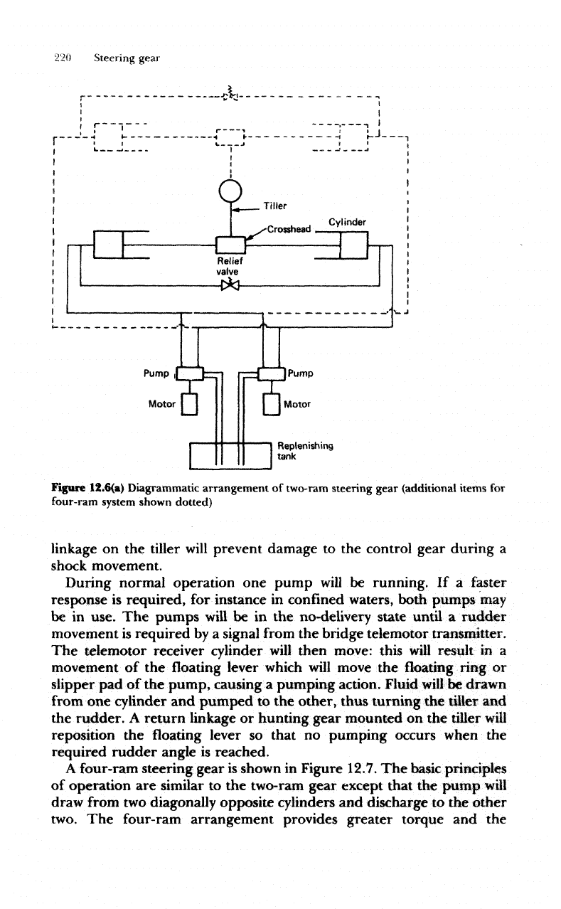
Figure
12.6(a)
Diagrammatic arrangement
of
two-ram
steering gear (additional items
for
four-ram
system
shown
dotted)
linkage
on the
tiller
will
prevent damage
to the
control gear during
a
shock
movement.
During
normal operation
one
pump
will
be
running.
If a
faster
response
is
required,
for
instance
in
confined waters, both pumps
may
be
in
use.
The
pumps
will
be in the
no-delivery state
until
a
rudder
movement
is
required
by a
signal
from
the
bridge telemotor transmitter.
The
telemotor receiver cylinder
will
then move: this
will
result
in a
movement
of the
floating
lever
which
will
move
the
floating ring
or
slipper
pad of the
pump, causing
a
pumping
action. Fluid
will
be
drawn
from
one
cylinder
and
pumped
to the
other,
thus turning
the
tiller
and
the
rudder.
A
return linkage
or
hunting gear mounted
on the
tiller
will
reposition
the
floating lever
so
that
no
pumping occurs
when
the
required rudder angle
is
reached.
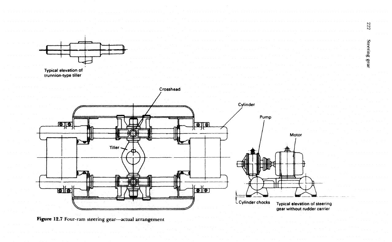
A
four-ram steering gear
is
shown
in
Figure
12.7.
The
bask
principles
of
operation
are
similar
to the
two-ram
gear
except that
the
pump
will
draw
from
two
diagonally opposite cylinders
and
discharge
to the
other
two.
The
four-ram arrangement provides greater torque
and the
Steering
gear
221
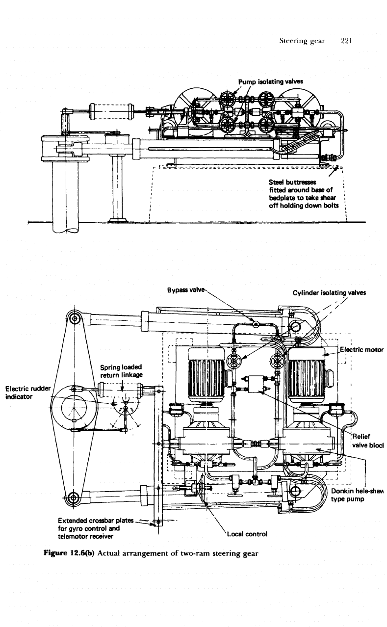
Pump
isolating
valves
Steel
buttresses
fitted
around
base
of
bedplate
to
take
shear
off
holding
down bolts
Bypass
valve-
Cylinder
isolating
valves
Electric
rudder
indicator
Electric motor
j
[Relief
'
valve
blocl
Donkin
hele-shaw
type pump
Extended
crossbar plates
for
gyro
control
and
telemotor
receiver
Local
control
Figure
I2.6(b)
Actual
arrangement
of
two-ram
steering gear
Typical elevation
of
trunnion-type
tiller
Crosshead
Cylinder
Pump
Motor
Cylinder
chocks
Typical
elevation
of
steering
gear
without
rudder
carrier
Figure
12.7
Four-ram steering
gear—actual
arrangement

Steering gear
223
flexibility of
different
arrangements
in the
event
of
component
failure.
Either
pump
can be
used
with
all
cylinders
or
with
either
the two
port
or
two
starboard
cylinders. Various valves must
be
open
or
closed
to
provide
these arrangements.
The use of a
control
valve
block incorporating rudder shock relief
valves,
pump isolating valves,
ram
isolating
and
bypass valves,
offers
greater
flexibility
with
a
four-ram
steering gear.
In
normal operation
one
pump
can
operate
all
cylinders.
In an
emergency situation
the
motor
or a
pair
of
hand pumps could
be
used
to
operate
two
port
rams,
two
starboard rams,
two
forward rams
or two
after
rams.
The
crosshead arrangement
on the
four-ram type steering gear
described
incorporates
what
is
known
as the
'Rapson
Slide'.
This
provides
a
mechanical advantage
which
increases
with
the
angle turned
through.
The
crosshead arrangement
may use
either
a
forked
tiller
or a
round
arm
tiller (Figure 12.8).
The
round
arm
tiller
has a
centre
crosshead
which
is
free
to
slide along
the
tiller.
Each
pair
of
rams
is
joined
so as to
form
a
double bearing
in
which
the
trunnion arms
of the
crosshead
are
mounted.
The
straight line movement
of the
rams
is
thus
converted into
an
angular tiller movement.
In the
forked
tiller
arrangement
the ram
movement
is
transferred
to the
tiller through
swivel
blocks.
To
charge
the
system
with
fluid
it is first
necessary
to fill
each
cylinder
then
replace
the filling
plugs
and
close
the air
cocks.
The
cylinder bypass
valves
should
be
opened
and the
replenishing tanks
filled. The air
vents
on the
pumps should
be
opened
until
oil
discharges
free
of
air,
the
pumps
set to
pump
and
then turned
by
hand, releasing
air at the
appropriate pair
of
cylinders
and
pumping into each pair
of
cylinders
in
Ram
Ram
Round
arm
tiller
C
N
;
>
•10
•!
]
•
.
j
t V
\J
o
Forked
"tiller
I/
(a]
Round
arm
tiller
Figure
12.8
Crosshead
arrangements
(b)
Forked
tiller
224
Steering gear
turn
using
the
hand control mechanism.
The
motor should then
be
started
up
and, using
the
local hand control, operation
of the
steering
gear checked.
Air
should again
be
released from
the
pressurised
cylinders
and the
pumps through
the
appropriate vents.
During
normal operation
the
steering gear should
be
made
to
move
at
least once every
two
hours
to
ensure
self lubrication
of the
moving
parts.
No
valves
in the
system, except bypass
and air
vent, should
be
closed.
The
replenishing tank
level
should
be
regularly checked and,
if
low,
refilled
and the
source
of
leakage found. When
not in
use, that
is, in
port,
the
steering motors should
be
switched off.
Also
the
couplings
of
the
motors should
be
turned
by
hand
to
check that
the
pump
is
moving
freely.
If
there
is any
stiffness
the
pump should
be
overhauled.
As
with
any
hydraulic
system
cleanliness
is
essential
when
overhauling equip-
ment
and
only
linen
cleaning
cloths should
be
used.
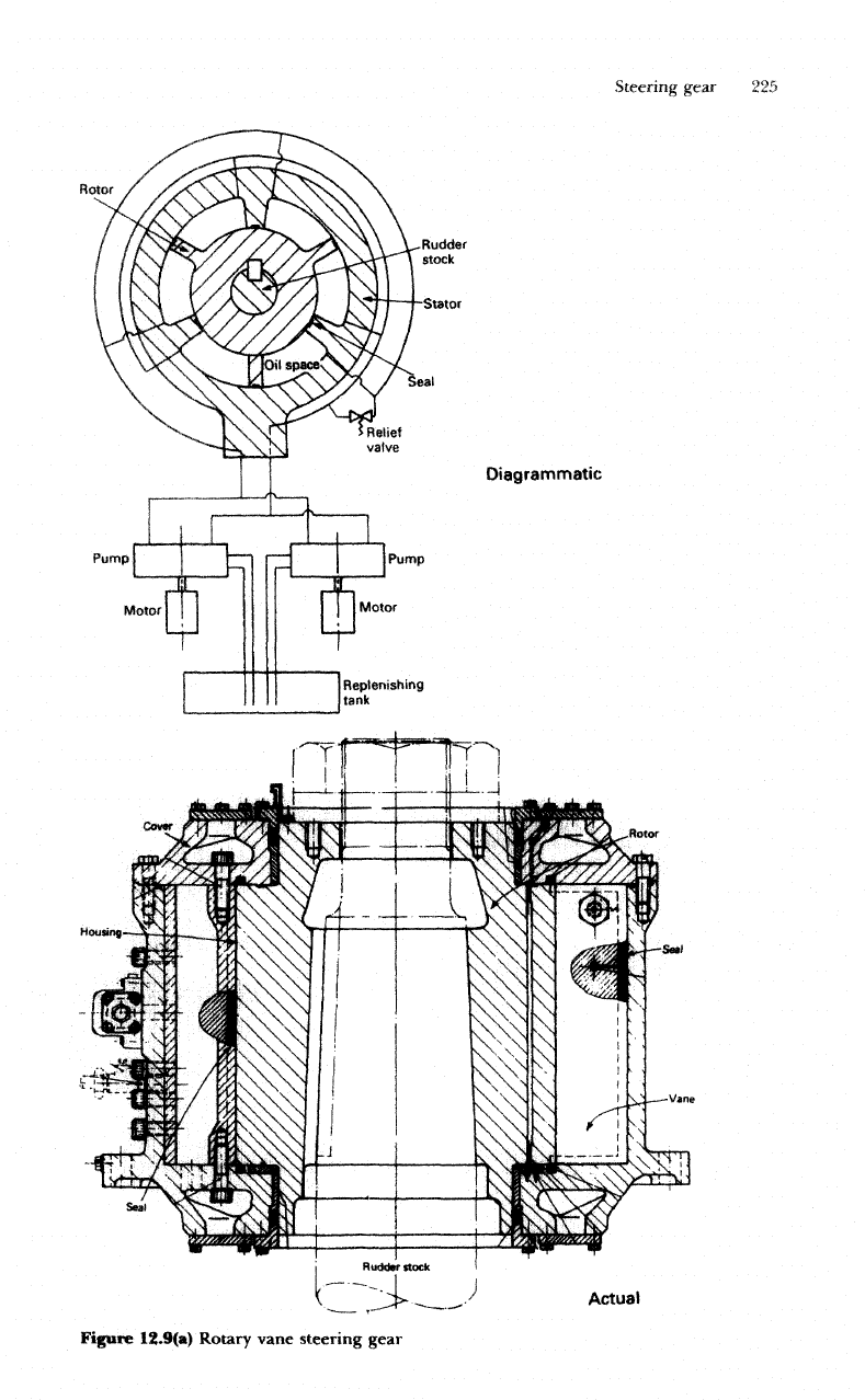
Rotary
vane
type
With
this type
of
steering gear
a
vaned rotor
is
securely fastened onto
the
rudder
stock
(Figure
12.9).
The
rotor
is
able
to
move
in a
housing
which
is
solidly attached
to the
ship's structure. Chambers
are
formed
between
the
vanes
on the
rotor
and the
vanes
in the
housing.
These
chambers
will
vary
in
size
as the
rotor
moves
and can be
pressurised
since
sealing strips
are fitted on the
moving
faces.
The
chambers either
side
of the
moving vane
are
connected
to
separate pipe systems
or
manifolds.
Thus
by
supplying
hydraulic
fluid
to
all
the
chambers
to the
left
of the
moving vane
and
drawing
fluid
from
all the
chambers
on
the
right, the
rudder
stock
can be
made
to
turn anti-clockwise. Clockwise
movement
will
occur
if
pressure
and
suction
supplies
are
reversed.
Three
vanes
are
usual
and
permit
an
angular movement
of
70°:
the
vanes
also
act as
stops
limiting
rudder movement.
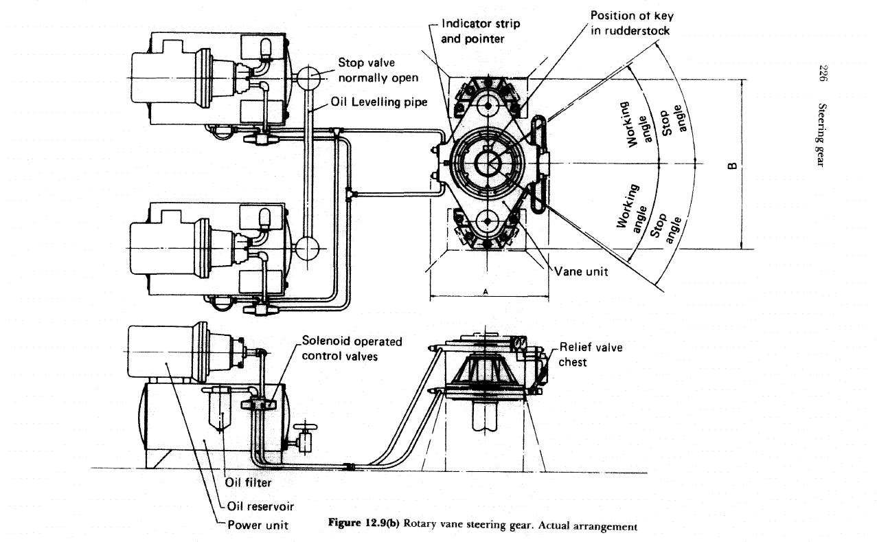
The
hydraulic
fluid is
supplied
by a
variable delivery pump
and
control
will
be
electrical,
as
described earlier.
A
relief
valve
is fitted in the
system
to
prevent
overpressure
and
allow
for
shock
loading
of the
rudder.
All-electric
steering
Steering gears
which
comprise electric control, electric power unit
and
electrical transmission,
are of two
types,
the
Ward—Leonard
system
and
the
Direct Single Motor system. Both types have
a
geared-down motor
drive
via a
pinion
to a
toothed quadrant.
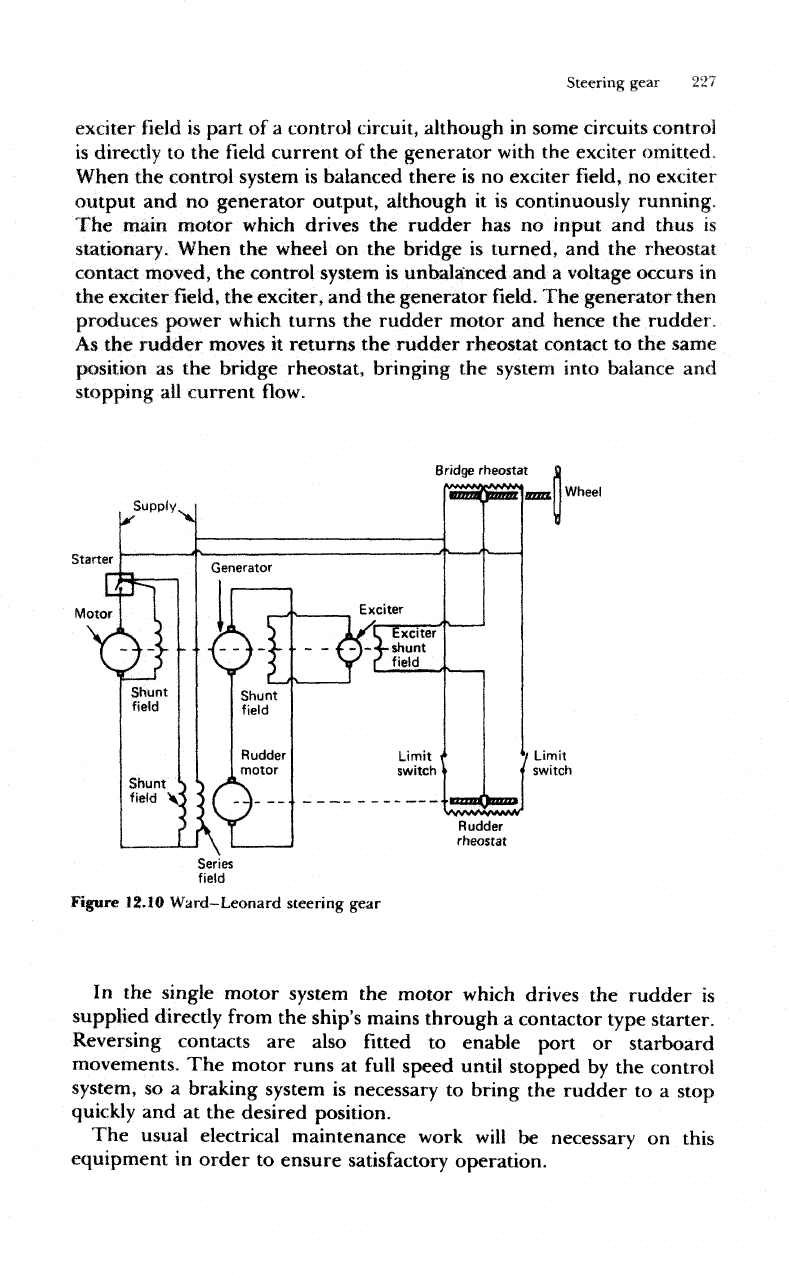
A
Ward—Leonard
arrangement
is
shown
diagrammatically
in
Figure
12.10.
A
continuously running motor-generator
set has a
directly
coupled
exciter
to
provide
the field
current
of the
generator.
The
Steering gear
225
Rotor
Diagrammatic
Actual
Figure
12.9(a)
Rotary vane steering gear
Indicator
strip
and
pointer
Position
of
key
in
rudderstock
Stop
valve
normally
open
Solenoid
operated
control
valves
Oil
filter
-Oil reservoir
•Power
unit Figure
12.9(b)
Rotary
vane
steering gear,
Actuai
arrangement
C/5
I
1
era
Steering
gear
227
exciter
field
is
part
of a
control circuit, although
in
some circuits
control
is
directly
to the
field
current
of the
generator
with
the
exciter omitted,
When
the
control system
is
balanced there
is no
exciter
field, no
exciter
output
and no
generator output, although
it is
continuously running.
The
main motor which drives
the
rudder
has no
input
and
thus
is
stationary.
When
the
wheel
on the
bridge
is
turned,
and the
rheostat
contact
moved,
the
control system
is
unbalanced
and a
voltage occurs
in
the
exciter
field, the
exciter,
and the
generator
field. The
generator then
produces power which turns
the
rudder
motor
and
hence
the
rudder,
As
the
rudder
moves
it
returns
the
rudder
rheostat
contact
to the
same
position
as the
bridge rheostat, bringing
the
system
into
balance
and
stopping
all
current
flow.
Supply
Starter
Motor
Rudder
rheostat
Figure
12.10
Ward-Leonard
steering
gear
In
the
single motor system
the
motor which drives
the
rudder
is
supplied directly
from
the
ship's mains through
a
contactor type
starter.
Reversing
contacts
are
also
fitted
to
enable port
or
starboard
movements.
The
motor runs
at
full
speed until stopped
by the
control
system,
so a
braking system
is
necessary
to
bring
the
rudder
to a
stop
quickly
and at the
desired
position.
The
usual electrical maintenance
work
will
be
necessary
on
this
equipment
in
order
to
ensure
satisfactory
operation.
228
Steering gear
Twin
system
steering
gears
To
meet
the
automatic changeover
within
the 45
seconds required
for
tankers
of
10000
ton
gross tonnage
and
above,
a
number
of
designs
are
available.
Two
will
be
described,
one
for a ram
type steering gear
and
one for a
rotary
vane
type steering
gear.
In
each case
two
independent
systems
provide
the
power source
to
move
the
tiller,
the
failure
of one
resulting
in a
changeover
to the
other.
The
changeover
is
automatic
and
is
achieved
within
45
seconds.
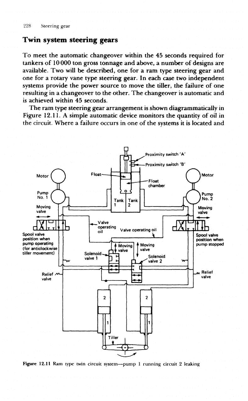
The ram
type steering gear arrangement
is
shown
diagrammatically
in
Figure
12.11.
A
simple automatic device monitors
the
quantity
of oil in
the
circuit. Where
a
failure
occurs
in one of the
systems
it is
located
and
Proximity
switch
'A'
Proximity switch
'B'
Motor
Pump
No.
1
Motor
Pump
No,
2
Spool
valve
position
when
pump
stopped
Spool
valve
position
when
pump
operating
(for anticlockwise
tiller
movement)
Figure
12.11
Ram
type
twin
circuit
system—pump
1
running
circuit
2
leaking
Steering gear
229
that
circuit
is
isolated.
The
other
system provides uninterrupted steering
and
alarms
are
sounded
and
displayed.
Consider pump
1 in
operation
and
pump
2
placed
on
automatic
reserve
by the
selector
switch.
If a
leak
develops
in
circuit
2 the float
chamber
oil
level
will
fall
and
proximity
switch
A on the
monitor
will
be
activated
to
close
the
solenoid
valve
2
which
isolates
circuit
2 and
bypasses
the
cylinders
in
that circuit.
An
alarm
will
also
be
given.
If the
leak
is in
circuit
1
however,
the float
chamber
oil
level
will
fall
further
until
proximity
switch
B
is
activated. This
will
cut off the
power
supply
to
motor
1 and
solenoid
valve
1 and
connect
the
supply
to
motor
2 and
solenoid
valve
2,
thus isolating circuit
1. If
pump
2
were running
and
pump
1
in.reserve,
a
similar changeover would occur. While
a
two
cylinder
system
has
been described this system
will
operate equally
well
with
four
double acting cylinders.
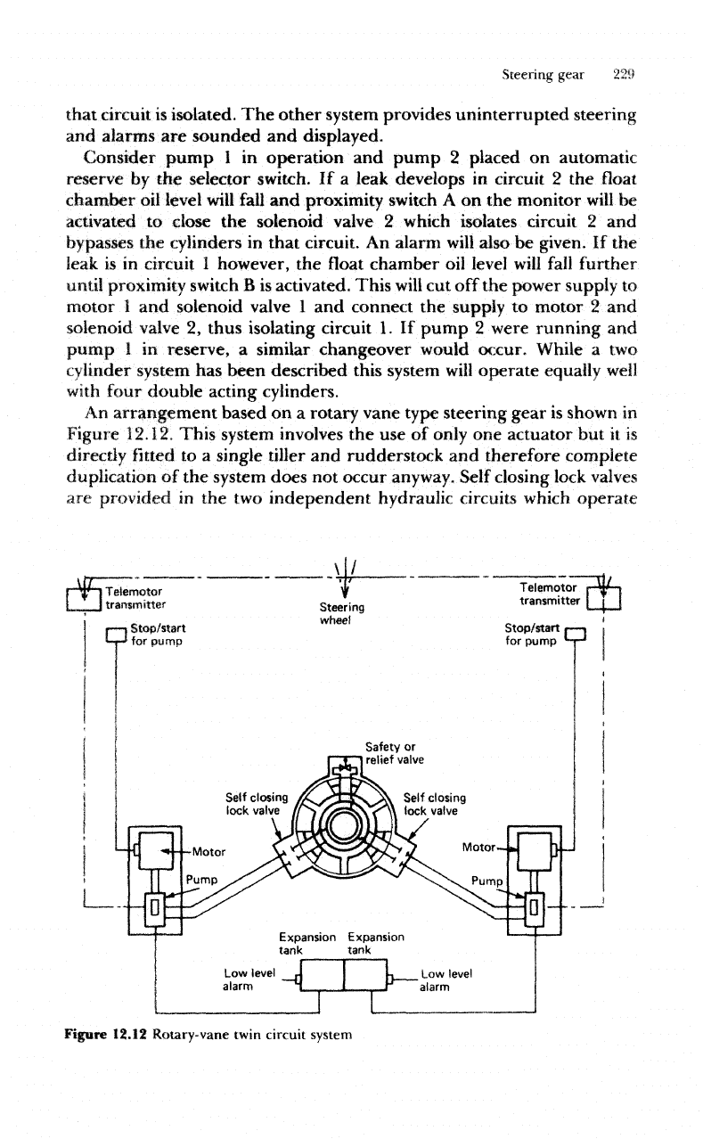
An
arrangement based
on a
rotary vane type steering gear
is
shown
in
Figure
12.12,
This system
involves
the use of
only
one
actuator
but it is
directly
fitted to a
single tiller
and
rudderstock
and
therefore complete
duplication
of the
system
does
not
occur
anyway.
Self closing lock
valves
are
provided
in the two
independent hydraulic circuits which operate
F
W
I
Telemotor
L_
i
transmitter
n
Stop/start
for
pump
Steering
wheel
Telemotor
r
W
i
transmitter
III
Stop/start
f—|
Expansion
Expansion
tank tank
Figure 12.12 Rotary-vane
twin
circuit system