Taylor D.A. Introduction to marine engineering
Подождите немного. Документ загружается.

210
Shafting
and
propellers
welding
and
subsequent heat treatment.
A
temporary repair
for
deep
pits
or
holes
could
be
done
with
a
suitable
resin
filler.
The
steering gear provides
a
movement
of the
rudder
in
response
to a
signal
from
the
bridge.
The
total system
may be
considered made
up
of
three
parts,
control
equipment,
a
power
unit
and a
transmission
to
the
rudder
stock.
The
control equipment conveys
a
signal
of
desired
rudder
angle
from
the
bridge
and
activates
the
power unit
and
transmission system
until
the
desired angle
is
reached.
The
power unit provides
the
force,
when
required
and
with
immediate
effect,
to
move
the
rudder
to the
desired
angle.
The
transmission system,
the
steering gear,
is the
means
by
which
the
movement
of the
rudder
is
accomplished.
Certain requirements
must
currently
be met by a
ship's
steering
system.
There
must
be two
independent means
of
steering, although
where
two
identical power units
are
provided
an
auxiliary
unit
is not
required.
The
power
and
torque capability must
be
such that
the
rudder
can
be
swung
from
35° one
side
to 35* the
other side
with
the
ship
at
maximum
speed,
and
also
the
time
to
swing
from
35° one
side
to 30° the
other side must
not
exceed
28
seconds.
The
system must
be
protected
from
shock loading
and
have pipework
which
is
exclusive
to it as
well
as
be
constructed
from
approved materials. Control
of the
steering
gear
must
be
provided
in the
steering gear compartment.
Tankers
of
10000
ton
gross tonnage
and
upwards must have
two
independent
steering
gear control systems
which
are
operated
from
the
bridge.
Where
one
fails,
changeover
to the
other must
be
immediate
and
achieved
from
the
bridge position.
The
steering gear
itself
must
comprise
two
independent systems where
a
failure
of one
results
in an
automatic
changeover
to the
other
within
45
seconds.
Any of
these
failures
should result
in
audible
and
visual alarms
on the
bridge.
Steering gears
can be
arranged
with
hydraulic control equipment
known
as
a
'telemeter',
or
with
electrical control equipment.
The
power
unit
may in
turn
be
hydraulic
or
electrically operated. Each
of
these
units
will
be
considered
in
turn,
with
the
hydraulic unit pump being
considered
first.
A
pump
is
required
in the
hydraulic
system
which
can
immediately
pump
fluid
in
order
to
provide
a
hydraulic
force
that
will
move
the
rudder. Instant response does
not
allow
time
for the
pump
to
211
Chapter
12
Steering
gear
212
Steering gear
be
switched
on and
therefore
a
constantly
running pump
is
required
which
pumps
fluid
only
when
required.
A
variable
delivery
pump
provides
this
facility.
Variable
delivery
pumps
A
number
of
different
designs
of
variable
delivery
pump exist. Each
has
a
means
of
altering
the
pump stroke
so
that
the
amount
of oil
displaced
will
vary
from
zero
to
some designed maximum value. This
is
achieved
by
use of a floating
ring,
a
swash
plate
or a
slipper pad.
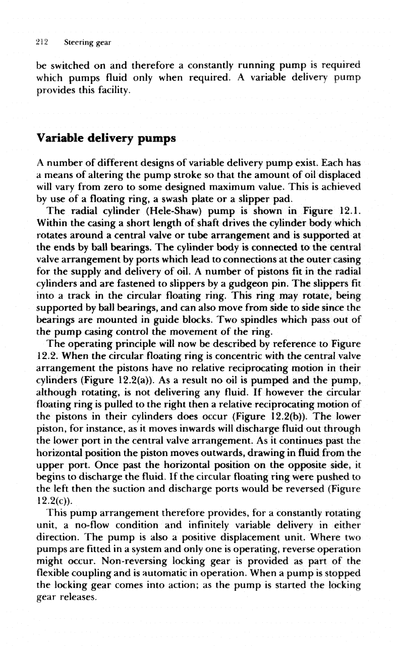
The
radial
cylinder
(Hele-Shaw)
pump
is
shown
in
Figure
12.1.
Within
the
casing
a
short length
of
shaft
drives
the
cylinder body which
rotates around
a
central valve
or
tube arrangement
and is
supported
at
the
ends
by
ball
bearings.
The
cylinder body
is
connected
to the
central
valve
arrangement
by
ports
which
lead
to
connections
at the
outer
casing
for
the
supply
and
delivery
of
oil.
A
number
of
pistons
fit in the
radial
cylinders
and are
fastened
to
slippers
by a
gudgeon pin.
The
slippers
fit
into
a
track
in the
circular floating ring.
This
ring
may
rotate,
being
supported
by
ball bearings,
and can
also move
from
side
to
side since
the
bearings
are
mounted
in
guide blocks.
Two
spindles which pass
out of
the
pump casing control
the
movement
of the
ring.
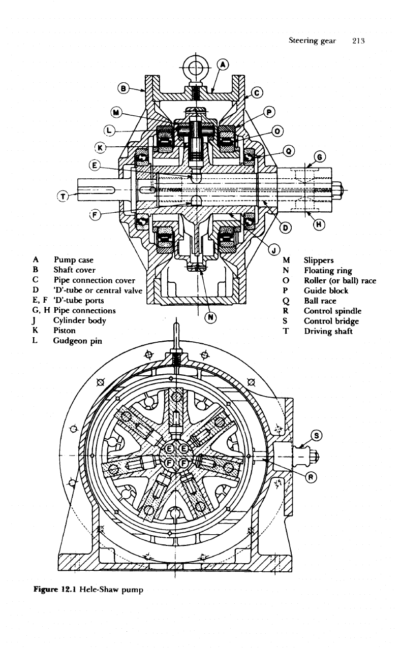
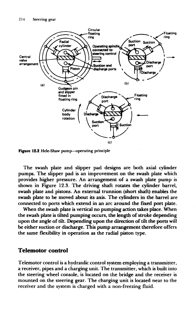
The
operating
principle
will
now be
described
by
reference
to
Figure
12.2.
When
the
circular
floating
ring
is
concentric
with
the
central
valve
arrangement
the
pistons have
no
relative reciprocating motion
in
their
cylinders (Figure
12.2(a)).
As a
result
no oil is
pumped
and the
pump,
although rotating,
is not
delivering
any fluid. If
however
the
circular
floating
ring
is
pulled
to the
right then
a
relative reciprocating motion
of
the
pistons
in
their cylinders
does
occur (Figure
12.2(b)).
The
lower
piston,
for
instance,
as it
moves inwards
will
discharge
fluid out
through
the
lower port
in the
central
valve
arrangement.
As it
continues past
the
horizontal position
the
piston moves outwards, drawing
in fluid
from
the
upper
port.
Once past
the
horizontal position
on the
opposite
side,
it
begins
to
discharge
the fluid. If the
circular
floating
ring were pushed
to
the
left
then
the
suction
and
discharge ports would
be
reversed (Figure
12.2(c)).
This
pump arrangement therefore provides,
for a
constantly rotating
unit,
a
no-flow
condition
and
infinitely
variable delivery
in
either
direction.
The
pump
is
also
a
positive displacement unit. Where
two
pumps
are fitted in a
system
and
only
one is
operating, reverse operation
might
occur. Non-reversing locking gear
is
provided
as
part
of the
flexible
coupling
and is
automatic
in
operation. When
a
pump
is
stopped
the
locking gear comes into action;
as the
pump
is
started
the
locking
gear releases.
Steering
gear
233
A
Pump case
B
Shaft cover
C
Pipe connection cover
D
'D'-tube
or
central
valve
E,
F
'D'-tube
ports
G,
H
Pipe connections
j
Cylinder body
K
Piston
L
Gudgeon
pin
Slippers
Floating ring
Roller
(or
ball) race
Guide block
Ball
race
Control spindle
Control bridge
Driving
shaft
Figure 12.1 Hele-Shaw pump
214
Steering gear
Circular
•floating
ring
Floating
ring
Central
valve
arrangement
(a)
(b)
Gudgeon
pin
and
dipper
fitted
in
floating ring
Cylinder
body
rotation
Floating
ring
Figure 12.2
Hele-Shaw
pump—operating
principle
The
swash
plate
and
slipper
pad
designs
are
both axial cylinder
pumps.
The
slipper
pad is an
improvement
on the
swash
plate
which
provides higher pressure.
An
arrangement
of a
swash
plate pump
is
shown
in
Figure
12.3.
The
driving
shaft
rotates
the
cylinder barrel,
swash
plate
and
pistons.
An
external
trunnion (short shaft) enables
the
swash
plate
to be
moved
about
its
axis.
The
cylinders
in the
barrel
are
connected
to
ports
which
extend
in an arc
around
the
fixed
pott
plate.
When
the
swash
plate
is
vertical
no
pumping action takes
place.
When
the
swash plate
is
tilted
pumping occurs,
the
length
of
stroke depending
upon
the
angle
of
tilt. Depending upon
the
direction
of
tilt
the
ports
will
be
either suction
or
discharge. This pump arrangement therefore
offers
the
same
flexibility
in
operation
as the
radial
piston type.
Telemotor
control
Telemotor control
is a
hydraulic control
system
employing
a
transmitter,
a
receiver, pipes
and a
charging unit.
The
transmitter,
which
is
built
into
the
steering
wheel
console,
is
located
on the
bridge
and the
receiver
is
mounted
on the
steering
gear.
The
charging unit
is
located near
to
the
receiver
and the
system
is
charged
with
a
non-freezing
fluid.
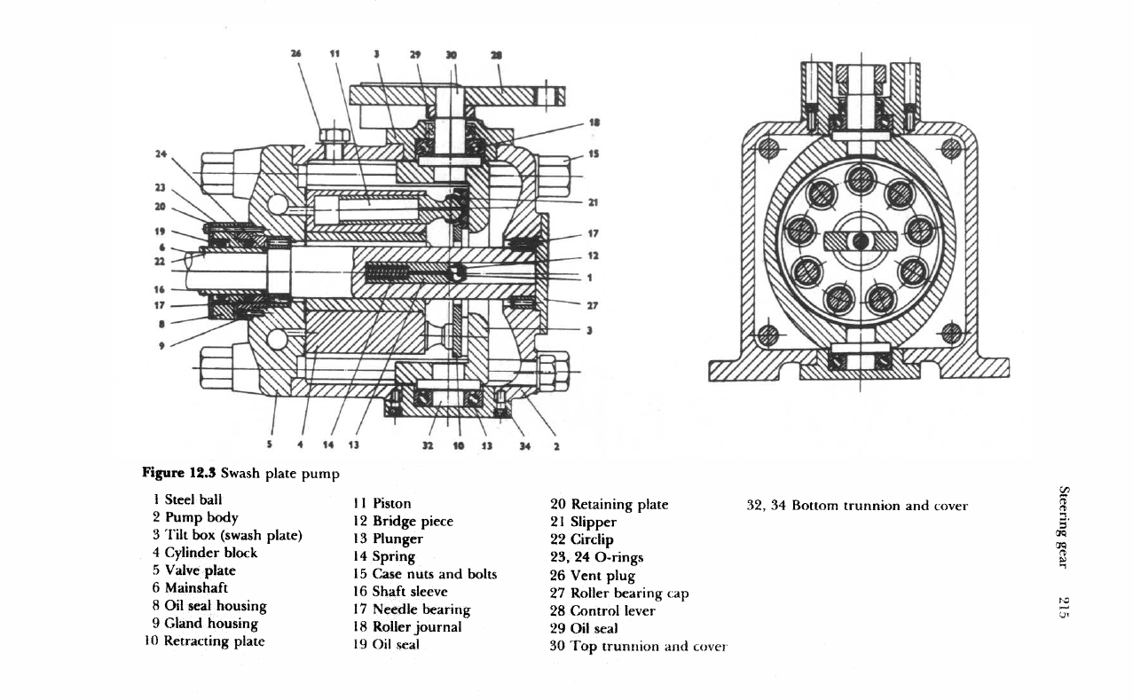
Figure 12.3
Swash
piate pump
1
Steel ball
2
Pump body
3
Tilt
box
(swash plate)
4
Cylinder block
5
Valve
plate
6
Mainshaft
8 Oil
seal
housing
9
Gland housing
10
Retracting plate
11
Piston
12
Bridge
piece
13
Plunger
14
Spring
15
Case nuts
and
bolts
16
Shaft
sleeve
17
Needle bearing
18
Roller journal
19
Oil
seal
20
Retaining plate
21
Slipper
22
Circlip
23, 24
O-rings
26
Vent
plug
27
Roller bearing
cap
28
Control
lever
29 Oil
seal
30
Top
trunnion
and
cover
32, 34
Bottom
trunnion
and
cover
216
Stee
ring gear
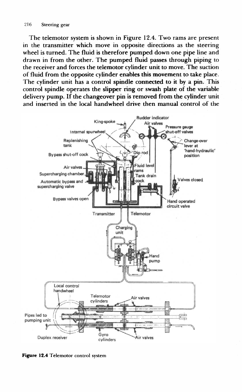
The
telemotor
system
is
shown
in
Figure 12.4.
Two
rams
are
present
in
the
transmitter
which
move
in
opposite directions
as the
steering
wheel
is
turned.
The fluid is
therefore pumped down
one
pipe line
and
drawn
in
from
the
other.
The
pumped
fluid
passes
through piping
to
the
receiver
and
forces
the
telemotor cylinder unit
to
move.
The
suction
of
fluid
from
the
opposite
cylinder
enables this movement
to
take place.
The
cylinder unit
has a
control spindle connected
to it by a
pin. This
control
spindle
operates
the
slipper
ring
or
swash
plate
of the
variable
delivery
pump.
If the
changeover
pin is
removed from
the
cylinder unit
and
inserted
in the
local
handwheel
drive then manual control
of the
King-spoke
_i
I
nternal
spu
rwheei
_
-"
""'^
Replenishing
tank
Rudder
indicator
Air
valves
Pressure
gauge
shut-off
valves
By
pass
shut-off
code
Air
valves
Supercharging
chamber
Automatic
bypass
and
supercharging
valve
Bypass
valves
open
Pipes
led to
pumping
unit
Change-over
lever
at
'hand-hydraulic'
position
Valves
closed.
Gyro
cylinders
Duplex
receiver
Figure 12.4
Telemotor
control
system
Air
valves
Steering gear
21"
steering
gear
is
possible. Stops
are
fitted
on the
receiver
to
limit
movement
to the
maximum
rudder angle required.
The
charging unit
consists
of a
tank,
a
pump,
and
shut-off
cocks
for
each
and is
fitted
in the
main
piping between
the
transmitter
and
receiver.
In
the
transmitter
a
replenishing tank surrounds
the
rams, ensuring
that
air
cannot enter
the
system.
A
bypass between
the two
cylinders
opens
as the
wheel passes midships.
Also
at mid
position
the
supercharging unit provides
a
pressure
in the
system which ensures
rapid response
of the
system
to a
movement
of the
wheel. This
supercharging unit also draws
in
replenishing
fluid
if
required
in the
system,
and
provides
a
relief valve arrangement
if the
pressure
is too
high.
Pressure gauges
are
connected
to
each
main
pipeline
and air
vent
cocks
are
also provided.
In
normal operation
the
working pressure
of
about
20 to 30
bar,
or
the
manufacturer's given figure, should
not be
exceeded.
The
wheel
should
not be
forced beyond
the
'hard
over'
position
as
this
will
strain
the
gear.
The
replenishing
tank
should
be
checked regularly
and any
lubrication
points should receive attention.
Any
leaking
or
damaged
equipment
must
be
repaired
or
replaced
as
soon
as
possible.
The
system
should
be
regularly checked
for
pressure tightness.
The
rudder
response
to
wheel movement should
be
checked
and if
sluggish
or
slow
then
air
venting undertaken.
If,
after long service,
air
venting
does
not
remove
sluggishness,
it may be
necessary
to
recharge
the
system
with
new fluid.
Wheel
To
pump
control
rod
Mains
supply
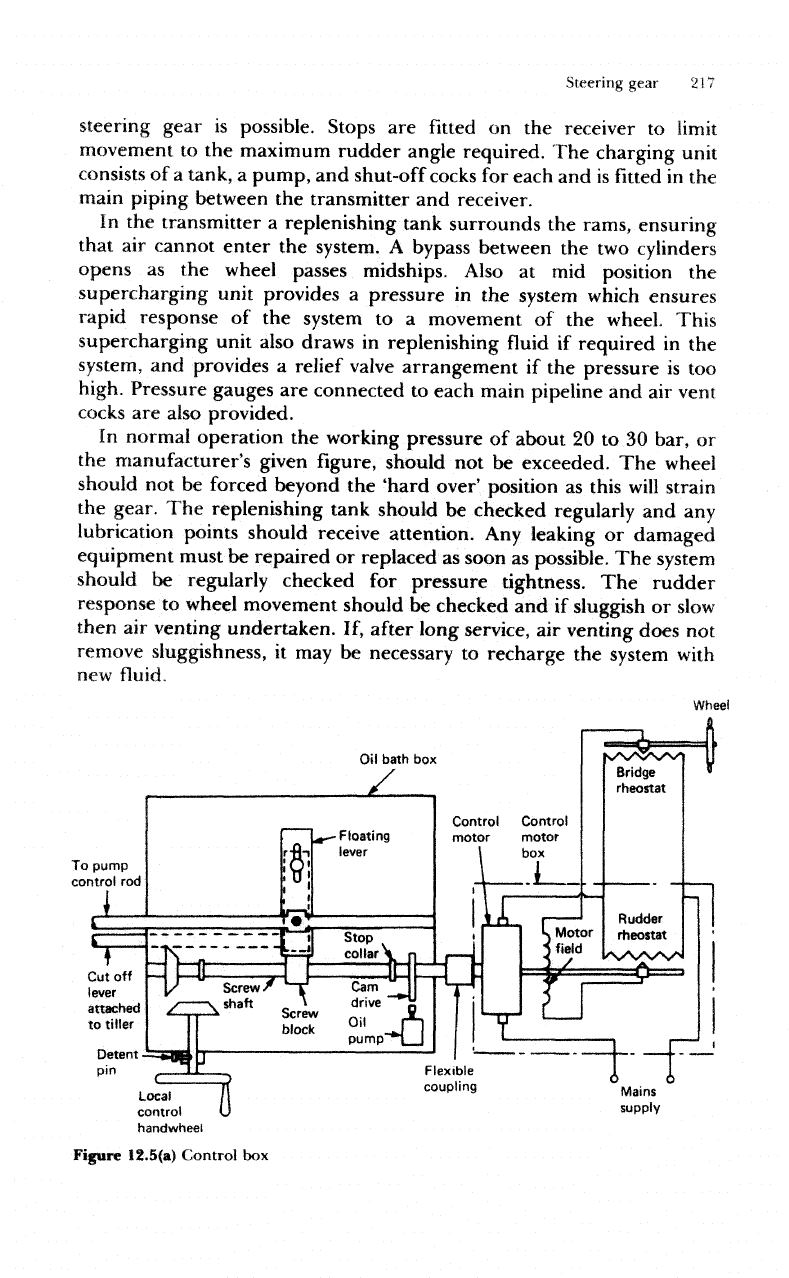
Figure
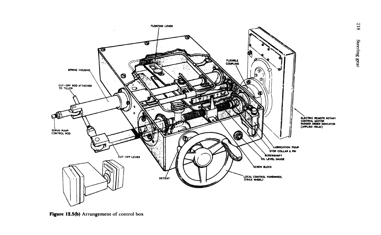
12.5(a)
Control
box
218
Steering gear
8
g.
Steering
gear
239
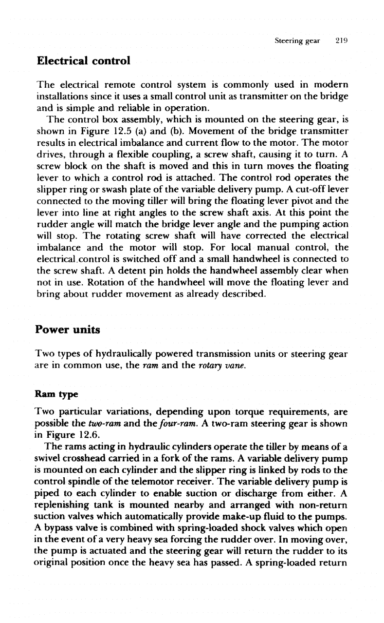
Electrical
control
The
electrical remote control
system
is
commonly
used
in
modern
installations
since
it
uses
a
small control unit
as
transmitter
on the
bridge
and is
simple
and
reliable
in
operation.
The
control
box
assembly,
which
is
mounted
on the
steering gear,
is
shown
in
Figure 12.5
(a) and
(b). Movement
of the
bridge transmitter
results
in
electrical imbalance
and
current
flow to the
motor.
The
motor
drives,
through
a
flexible
coupling,
a
screw
shaft,
causing
it to
turn.
A
screw
block
on the
shaft
is
moved
and
this
in
turn moves
the
floating
lever
to
which
a
control
rod is
attached.
The
control
rod
operates
the
slipper ring
or
swash
plate
of the
variable delivery pump.
A
cut-off lever
connected
to the
moving
tiller
will
bring
the
floating lever pivot
and the
lever
into
line
at
right angles
to the
screw
shaft
axis.
At
this point
the
rudder angle
will
match
the
bridge lever angle
and the
pumping action
will
stop.
The
rotating screw
shaft
will
have corrected
the
electrical
imbalance
and the
motor
will
stop.
For
local manual control,
the
electrical.control
is
switched
off and a
small
handwheel
is
connected
to
the
screw
shaft.
A
detent
pin
holds
the
handwheel assembly clear when
not in
use. Rotation
of the
handwheel
will
move
the
floating
lever
and
bring
about rudder
movement
as
already described.
Power
units
Two
types
of
hydraulically powered transmission
units
or
steering gear
are in
common use,
the ram and the
rotary
vane.
Ram
type
Two
particular variations, depending upon
torque
requirements,
are
possible
the
two-ram
and the
four-ram.
A
two-ram
steering gear
is
shown
in
Figure 12.6.
The
rams acting
in
hydraulic cylinders
operate
the
tiller
by
means
of a
swivel
crosshead
carried
in a
fork
of the
rams.
A
variable
delivery
pump
is
mounted
on
each cylinder
and the
slipper ring
is
linked
by
rods
to the
control spindle
of the
telemotor
receiver.
The
variable delivery pump
is
piped
to
each cylinder
to
enable suction
or
discharge from
either.
A
replenishing tank
is
mounted nearby
and
arranged
with non-return
suction
valves
which
automatically
provide make-up
fluid
to the
pumps.
A
bypass valve
is
combined
with
spring-loaded
shock valves which
open
in
the
event
of a
very heavy
sea
forcing
the
rudder
over.
In
moving over,
the
pump
is
actuated
and the
steering
gear
will
return
the
rudder
to its
original
position once
the
heavy
sea has
passed.
A
spring-loaded return