Tarek Ahmed. Reservoir engineering handbook
Подождите немного. Документ загружается.


where Q
g
= gas flow rate, Mscf/day
k = permeability, md
T = temperature, °R
z = gas compressibility factor
m
g
= gas viscosity, cp
It is recommended that the z-factor and gas viscosity be evaluated at
the average pressure p
avg
as defined by:
The method of calculating the gas flow rate by Equation 8-11 is called
the pressure-squared approximation method.
If both p
–
r
and p
wf
are lower than 2000 psi, Equation 8-11 can be
expressed in terms of the productivity index J as:
with
where
Example 8-1
The PVT properties of a gas sample taken from a dry gas reservoir are
given in the following table:
J
kh
Tz
r
r
s
g avg
e
w
=
Ê
Ë
Á
ˆ
¯
˜
-+
È
Î
Í
Í
˘
˚
˙
˙
1422 0 75( ) ln .m
(8 -14)
()
max
Q AOF J p
g
r
==
2
(8 -13)
QJpp
grwf
=-()
22
(8 -12)
p
pp
avg
r
wf
=
+
2
2
2
Q
kh p p
Tz
r
r
s
g
rwf
g avg
e
w
=
-
Ê
Ë
Á
ˆ
¯
˜
-+
È
Î
Í
Í
˘
˚
˙
˙
()
( ) ln .
22
1422 0 75m
(8 -11)
538 Reservoir Engineering Handbook
Reservoir Eng Hndbk Ch 08 2001-10-24 11:13 Page 538

p, psi m
g
, cp Z y, psi
2
/cp B
g
, bbl/scf
0 0.01270 1.000 0 —
400 0.01286 0.937 13.2 ¥ 10
6
0.007080
1200 0.01530 0.832 113.1 ¥ 10
6
0.00210
1600 0.01680 0.794 198.0 ¥ 10
6
0.00150
2000 0.01840 0.770 304.0 ¥ 10
6
0.00116
3200 0.02340 0.797 678.0 ¥ 10
6
0.00075
3600 0.02500 0.827 816.0 ¥ 10
6
0.000695
4000 0.02660 0.860 950.0 ¥ 10
6
0.000650
The reservoir is producing under the pseudosteady-state condition. The
following additional data is available:
k = 65 md h = 15¢ T = 600°R
r
e
= 1000¢ r
w
= 0.25¢ s = 0.4
Calculate the gas flow rate under the following conditions:
a. p
–
r
= 4000 psi, p
wf
= 3200 psi
b. p
–
r
= 2000 psi, p
wf
= 1200 psi
Use the appropriate approximation methods and compare results with
the exact solution.
Solution
a. Calculate Q
g
at p
–
r
= 4000 and p
wf
= 3200 psi:
Step 1. Select the approximation method. Because p
–
r
and p
wf
are both >
3000, the pressure-approximation method is used, i.e., Equation 8-9.
Step 2. Calculate average pressure and determine the corresponding gas
properties.
m
g
= 0.025 B
g
= 0.000695
p psi=
+
=
4000 3200
2
3600
Gas Well Performance 539
Reservoir Eng Hndbk Ch 08 2001-10-24 11:13 Page 539

Step 3. Calculate the gas flow rate by applying Equation 8-9.
Step 4. Recalculate Q
g
by using the pseudopressure equation, i.e., Equa-
tion 8-1.
b. Calculate Q
g
at p
–
r
= 2000 and p
wf
= 1058:
Step 1. Select the appropriate approximation method. Because p
–
r
and p
wf
≤ 2000, use the pressure-squared approximation.
Step 2. Calculate average pressure and the corresponding m
g
and z.
m
g
= 0.017 z = 0.791
Step 3. Calculate Q
g
by using the pressure-squared equation, i.e., Equa-
tion 8-11.
Q
Mscf day
g
=
-
Ê
Ë
ˆ
¯
--
È
Î
Í
˘
˚
˙
=
()()( )
()(.)(.)ln
.
..
,/
65 15 2000 1200
1422 600 0 017 0 791
1000
025
075 04
30 453
22
p psi=
+
=
2000 1200
2
1649
22
Q Mscf day
g
=
-
Ê
Ë
ˆ
¯
--
È
Î
Í
˘
˚
˙
=
()()( . .)()()
()()ln
.
..
,/
65 15 950 0 678 0 65 15 10
1422 600
1000
025
075 04
43 509
6
Q
Mscf day
g
=
-
Ê
Ë
ˆ
¯
--
È
Î
Í
˘
˚
˙
=
-
7 08 10 65 15 4000 3200
0 025 0 000695
1000
025
075 04
44 490
6
. ( )( )( )( )
(. )(. )ln
.
..
,/
540 Reservoir Engineering Handbook
Reservoir Eng Hndbk Ch 08 2001-10-24 11:13 Page 540

Step 4. Compare Q
g
with the exact value from Equation 8-1:
All of the mathematical formulations presented thus far in this chapter
are based on the assumption that laminar (viscous) flow conditions are
observed during the gas flow. During radial flow, the flow velocity
increases as the wellbore is approached. This increase of the gas velocity
might cause the development of a turbulent flow around the wellbore. If
turbulent flow does exist, it causes an additional pressure drop similar to
that caused by the mechanical skin effect.
As presented in Chapter 6 by Equations 6-164 through 6-166, the
semisteady-state flow equation for compressible fluids can be modified
to account for the additional pressure drop due the turbulent flow by
including the rate-dependent skin factor DQ
g
. The resulting pseu-
dosteady-state equations are given in the following three forms:
First Form : Pressure-Squared Approximation Form
where D is the inertial or turbulent flow factor and is given by Equation
6-160 as:
where the non-Darcy flow coefficient F is defined by Equation 6-156 as:
F
T
hr
g
gw
=
È
Î
Í
Í
˘
˚
˙
˙
-
3 161 10
12
2
.( )
bg
m
(8 -17)
D
FKh
T
=
1422
(8 -16)
Q
kh p p
Tz
r
r
sDQ
g
r
wf
g avg
e
w
g
=
-
(
)
Ê
Ë
Á
ˆ
¯
˜
-++
È
Î
Í
Í
˘
˚
˙
˙
2
2
1422 0 75( ) ln .m
(8 -15)
Q
Mscf day
g
=
-
Ê
Ë
ˆ
¯
--
È
Î
Í
˘
˚
˙
=
()()( . .)
()()ln
.
..
,/
65 15 304 0 113 1 10
1422 600
1000
025
075 04
30 536
6
Gas Well Performance 541
Reservoir Eng Hndbk Ch 08 2001-10-24 11:13 Page 541

where F = non-Darcy flow coefficient
k = permeability, md
T = temperature, °R
g
g
= gas gravity
r
w
= wellbore radius, ft
h = thickness, ft
b=turbulence parameter as given by Equation 6-157 as
b = 1.88 (10
-10
) k
-1.47
f
-0.53
Second Form: Pressure-Approximation Form
Third Form: Real Gas Potential (Pseudopressure) Form
Equations 8-15, 8-18, and 8-19 are essentially quadratic relationships
in Q
g
and, thus, they do not represent explicit expressions for calculating
the gas flow rate. There are two separate empirical treatments that can be
used to represent the turbulent flow problem in gas wells. Both treat-
ments, with varying degrees of approximation, are directly derived and
formulated from the three forms of the pseudosteady-state equations, i.e.,
Equations 8-15 through 8-17. These two treatments are called:
• Simplified treatment approach
• Laminar-inertial-turbulent (LIT) treatment
The above two empirical treatments of the gas flow equation are pre-
sented on the following pages.
Q
kh
T
r
r
sDQ
g
rwf
e
w
g
=
-
Ê
Ë
Á
ˆ
¯
˜
-++
È
Î
Í
Í
˘
˚
˙
˙
()
ln .
yy
1422 0 75
(8 -19)
Q
kh p p
T
r
r
sDQ
g
rwf
g g avg
e
w
g
=
-
Ê
Ë
Á
ˆ
¯
˜
-++
È
Î
Í
Í
˘
˚
˙
˙
-
708 10
075
6
.( ) ( )
( ) ln .mb
(8 -18)
542 Reservoir Engineering Handbook
Reservoir Eng Hndbk Ch 08 2001-10-24 11:13 Page 542

The Simplified Treatment Approach
Based on the analysis for flow data obtained from a large member of
gas wells, Rawlins and Schellhardt (1936) postulated that the relationship
between the gas flow rate and pressure can be expressed as:
where Q
g
= gas flow rate, Mscf/day
p
–
r
= average reservoir pressure, psi
n = exponent
C = performance coefficient, Mscf/day/psi
2
The exponent n is intended to account for the additional pressure drop
caused by the high-velocity gas flow, i.e., turbulence. Depending on the
flowing conditions, the exponent n may vary from 1.0 for completely
laminar flow to 0.5 for fully turbulent flow. The performance coefficient
C in Equation 8-20 is included to account for:
• Reservoir rock properties
• Fluid properties
• Reservoir flow geometry
Equation 8-20 is commonly called the deliverability or back-pres-
sure equation. If the coefficients of the equation (i.e., n and C) can be
determined, the gas flow rate Q
g
at any bottom-hole flow pressure p
wf
can be calculated and the IPR curve constructed.
Taking the logarithm of both sides of Equation 8-20 gives:
log (Q
g
) = log (C) + n log (p
–
r
2
- p
2
wf
) (8 - 21)
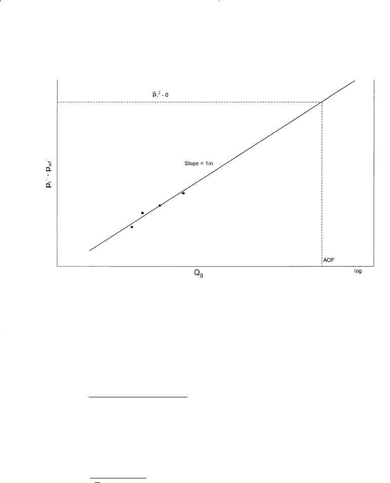
Equation 8-22 suggests that a plot of Q
g
versus (p
–
r
2
- p
2
wf
) on log-log
scales should yield a straight line having a slope of n. In the natural gas
industry the plot is traditionally reversed by plotting (p
–
r
2
- p
2
wf
) versus Q
g
on the logarithmic scales to produce a straight line with a slope of (1/n).
This plot as shown schematically in Figure 8-3 is commonly referred to
as the deliverability graph or the back-pressure plot.
QCpp
grwf
n
=-()
22
(8 - 20)
Gas Well Performance 543
Reservoir Eng Hndbk Ch 08 2001-10-24 11:13 Page 543

The deliverability exponent n can be determined from any two points
on the straight line, i.e., (Q
g1
, Dp
1
2
) and (Q
g2
, Dp
2
2
), according to the flow-
ing expression:
Given n, any point on the straight line can be used to compute the per-
formance coefficient C from:
The coefficients of the back-pressure equation or any of the other
empirical equations are traditionally determined from analyzing gas well
testing data. Deliverability testing has been used for more than sixty
years by the petroleum industry to characterize and determine the flow
potential of gas wells. There are essentially three types of deliverability
tests and these are:
C
Q
pp
g
rwf
n
=
-()
22
(8 - 23)
n
QQ
pp
gg
=
-
-
log( ) log( )
log( ) log ( )
12
1
2
2
2
DD
(8 - 22)
544 Reservoir Engineering Handbook
Figure 8-3. Well deliverability graph.
Reservoir Eng Hndbk Ch 08 2001-10-24 11:13 Page 544

• Conventional deliverability (back-pressure) test
• Isochronal test
• Modified isochronal test
These tests basically consist of flowing wells at multiple rates and
measuring the bottom-hole flowing pressure as a function of time. When
the recorded data is properly analyzed, it is possible to determine the
flow potential and establish the inflow performance relationships of the
gas well. The deliverability test is discussed later in this chapter for the
purpose of introducing basic techniques used in analyzing the test data.
The Laminar-Inertial-Turbulent (LIT) Approach
The three forms of the semisteady-state equation as presented by
Equations 8-15, 8-18, and 8-19 can be rearranged in quadratic forms for
the purpose of separating the laminar and inertial-turbulent terms com-
posing these equations as follows:
a. Pressure-Squared Quadratic Form
Equation 8-15 can be written in a more simplified form as:
with
where a = laminar flow coefficient
b = inertial-turbulent flow coefficient
Q
g
= gas flow rate, Mscf/day
z = gas deviation factor
k = permeability, md
m
g
= gas viscosity, cp
b
Tz
kh
D
g
=
Ê
Ë
Á
ˆ
¯
˜
1422 m
(8 - 26)
a
Tz
kh
r
r
s
g
e
w
=
Ê
Ë
Á
ˆ
¯
˜
Ê
Ë
Á
ˆ
¯
˜
-+
È
Î
Í
Í
˘
˚
˙
˙
1422
075
m
ln . (8 - 25)
pp aQbQ
rwf g
g
22 2
-= + (8 - 24)
Gas Well Performance 545
Reservoir Eng Hndbk Ch 08 2001-10-24 11:13 Page 545

The term (a Q
g
) in Equation 8-26 represents the pressure-squared
drop due to laminar flow while the term (b Q
2
g
) accounts for the pres-
sure-squared drop due to inertial-turbulent flow effects.
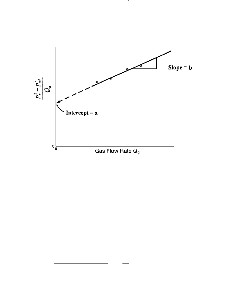
Equation 8-24 can be linearized by dividing both sides of the equa-
tion by Q
g
to yield:
The coefficients a and b can be determined by plotting
versus Q
g
on a Cartesian scale and should yield a straight line with a
slope of b and intercept of a. As presented later in this chapter, data
from deliverability tests can be used to construct the linear relation-
ship as shown schematically in Figure 8-4.
Given the values of a and b, the quadratic flow equation, i.e., Equa-
tion 8-24, can be solved for Q
g
at any p
wf
from:
Furthermore, by assuming various values of p
wf
and calculating the
corresponding Q
g
from Equation 8-28, the current IPR of the gas well
at the current reservoir pressure p
–
r
can be generated.
It should be pointed out the following assumptions were made in
developing Equation 8-24:
• Single phase flow in the reservoir
• Homogeneous and isotropic reservoir system
• Permeability is independent of pressure
• The product of the gas viscosity and compressibility factor, i.e., (m
g
z)
is constant.
This method is recommended for applications at pressures below
2000 psi.
Q
aa bp p
b
g
r
wf
=
-+ + -
(
)
2
2
2
4
2
(8 - 28)
pp
Q
rwf
g
22
-
Ê
Ë
Á
ˆ
¯
˜
pp
Q
abQ
rwf
g
g
22
-
=+ (8 - 27)
546 Reservoir Engineering Handbook
Reservoir Eng Hndbk Ch 08 2001-10-24 11:13 Page 546

b. Pressure-Quadratic Form
The pressure-approximation equation, i.e., Equation 8-18, can be
rearranged and expressed in the following quadratic form.
where
The term (a
1
Q
g
) represents the pressure drop due to laminar flow,
while the term (b
1
Q
2
g
) accounts for the additional pressure drop due to
b
B
kh
D
gg
1
3
141 2 10
=
È
Î
Í
Í
˘
˚
˙
˙
-
.( )( )m
(8 - 31)
a
B
kh
r
r
s
gg
e
w
1
3
141 2 10
075=
Ê
Ë
Á
ˆ
¯
˜
-+
È
Î
Í
Í
˘
˚
˙
˙
-
.( )( )
ln .
m
(8 - 30)
pp aQbQ
rwf g g
-= +
11
2
(8 - 29)
Gas Well Performance 547
Figure 8-4. Graph of the pressure-squared data.
Reservoir Eng Hndbk Ch 08 2001-10-24 11:13 Page 547
