Tarek Ahmed. Reservoir engineering handbook
Подождите немного. Документ загружается.


Solution
Step 1. Calculate the normalized water saturation for each core sample by
using Equation 5-36.
Core Sample #1 Core Sample #2 Core Sample #3
S*
w
S*
w
S*
w
S*
w
0.20 — — 0.000
0.25 0.000 — 0.111
0.30 0.125 0.000 0.222
0.40 0.375 0.238 0.444
0.50 0.625 0.476 0.667
0.60 0.875 0.714 0.889
0.65 1.000 0.833 1.000
0.72 — 1.000 —
Step 2. Determine relative permeability values at critical saturation for
each core sample.
Core 1 Core 2 Core 3
(k
ro
)S
wc
0.850 0.800 1.000
(k
rw
)S
or
0.400 0.500 0.35
Step 3. Calculate (k
–
ro
)
S
wc
and (k
–
rw
)
S
or
by applying Equations 5-39 and
5-40 to give:
(k
–
ro
)
S
wc
= 0.906
(k
–
rw
)
S
oc
= 0.402
Step 4. Calculate the normalized k
*
ro
and k
*
rw
for all core samples:
Core 1 Core 2 Core 3
S
w
S*
w
k*
ro
k*
rw
S*
w
k*
ro
k*
rw
S*
w
k*
ro
k*
rw
0.20 — — — — — — 0.000 1.000 0
0.25 0.000 1.000 0 — — — 0.111 0.872 0.023
0.30 0.125 0.887 0.045 0.000 1.000 0 0.222 0.839 0.077
0.40 0.375 0.655 0.230 0.238 0.741 0.154 0.444 0.663 0.251
0.50 0.625 0.414 0.495 0.476 0.491 0.382 0.667 0.463 0.503
0.60 0.875 0.154 0.818 0.714 0.252 0.646 0.889 0.215 0.817
0.65 1.000 0.000 1.000 0.833 0.139 0.788 1.000 0.000 1.000
0.72 — — — 1.000 0.000 1.000 — — —
308 Reservoir Engineering Handbook
Reservoir Eng Hndbk Ch 05 2001-10-24 09:52 Page 308

Step 5. Plot the normalized values of k
*
ro
and k
*
rw
versus S
*
w
for each core
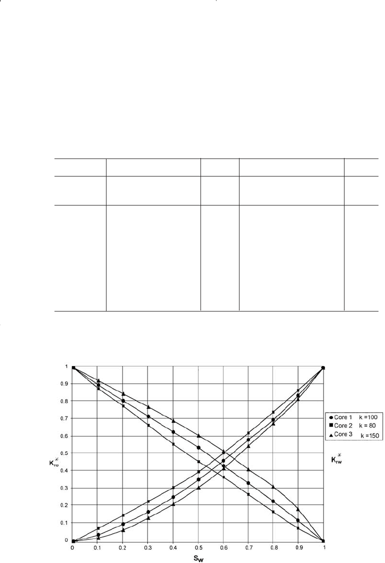
on a regular graph paper as shown in Figure 5-9.
Step 6. Select arbitrary values of S
*
w
and calculate the average k
*
ro
and k
*
rw
by applying Equations 5-37 and 5-38.
S*
w
k*
ro
(k*
ro
)
Avg
k*
rw
(k*
rw
)
avg
Core Core Core Core Core Core
123 123
0.1 0.91 0.88 0.93 0.912 0.035 0.075 0.020 0.038
0.2 0.81 0.78 0.85 0.821 0.100 0.148 0.066 0.096
0.3 0.72 0.67 0.78 0.735 0.170 0.230 0.134 0.168
0.4 0.63 0.51 0.70 0.633 0.255 0.315 0.215 0.251
0.5 0.54 0.46 0.61 0.552 0.360 0.405 0.310 0.348
0.6 0.44 0.37 0.52 0.459 0.415 0.515 0.420 0.442
0.7 0.33 0.27 0.42 0.356 0.585 0.650 0.550 0.585
0.8 0.23 0.17 0.32 0.256 0.700 0.745 0.680 0.702
0.9 0.12 0.07 0.18 0.135 0.840 0.870 0.825 0.833
Relative Permeability Concepts 309
Figure 5-9. Averaging relative permeability data.
Reservoir Eng Hndbk Ch 05 2001-10-24 09:52 Page 309

Step 7. Using the desired formation S
oc
and S
wc
(i.e., S
oc
= 0.30, S
wc
=
0.27), de-normalize the data to generate the required relative per-
meability data as shown below:
S*
w
(k*
ro
)
avg
(k*
rw
)
avg
S
w
= S*
w
(1 - S
wc
- S
oc
)k
ro
= 0.906 k
rw
= 0.402
+ S
wc
(k*
ro
)
avg
(k*
rw
)
avg
0.1 0.912 0.038 0.313 0.826 0.015
0.2 0.821 0.096 0.356 0.744 0.039
0.3 0.735 0.168 0.399 0.666 0.068
0.4 0.633 0.251 0.442 0.573 0.101
0.5 0.552 0.368 0.485 0.473 0.140
0.6 0.459 0.442 0.528 0.416 0.178
0.7 0.356 0.585 0.571 0.323 0.235
0.8 0.256 0.702 0.614 0.232 0.282
0.9 0.135 0.833 0.657 0.122 0.335
It should be noted that the proposed normalization procedure for
water-oil systems as outlined above could be extended to other systems,
i.e., gas-oil or gas-water.
THREE-PHASE RELATIVE PERMEABILITY
The relative permeability to a fluid is defined as the ratio of effective
permeability at a given saturation of that fluid to the absolute permeabili-
ty at 100% saturation. Each porous system has unique relative permeabil-
ity characteristics, which must be measured experimentally. Direct exper-
imental determination of three-phase relative permeability properties is
extremely difficult and involves rather complex techniques to determine
the fluid saturation distribution along the length of the core. For this rea-
son, the more easily measured two-phase relative permeability character-
istics are experimentally determined.
In a three-phase system of this type it is found that the relative perme-
ability to water depends only upon the water saturation. Since the water
can flow only through the smallest interconnect pores that are present in
the rock and able to accommodate its volume, it is hardly surprising that
the flow of water does not depend upon the nature of the fluids occupy-
ing the other pores. Similarly, the gas relative permeability depends only
upon the gas saturation. This fluid, like water, is restricted to a particular
range of pore sizes and its flow is not influenced by the nature of the
fluid or fluids that fill the remaining pores.
310 Reservoir Engineering Handbook
Reservoir Eng Hndbk Ch 05 2001-10-24 09:52 Page 310

The pores available for flow of oil are those that, in size, are larger
than pores passing only water, and smaller than pores passing only gas.
The number of pores occupied by oil depends upon the particular size
distribution of the pores in the rock in which the three phases coexist and
upon the oil saturation itself.
In general, the relative permeability of each phase, i.e., water, gas, and
oil, in a three-phase system is essentially related to the existing saturation
by the following functions:
k
rw
= f (S
w
) (5-41)
k
rg
= f (S
g
) (5-42)
k
ro
= f (S
w
, S
g
) (5-43)
Function 5-43 is rarely known and, therefore, several practical
approaches are proposed and based on estimating the three-phase relative
permeability from two sets of two-phase data:
Set 1: Oil-Water System
k
row
= f (S
w
)
k
rw
= f (S
w
)
Set 2: Oil-Gas System
k
rog
= f (S
g
)
k
rg
= f (S
g
)
where k
row
and k
rog
are defined as the relative permeability to oil in the
water-oil two-phase system and similarly k
rog
is the relative permeability
of oil in the gas-oil system. The symbol k
ro
is reserved for the oil relative
permeability in the three-phase system.
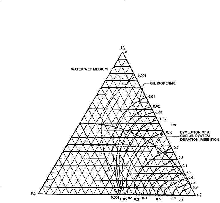
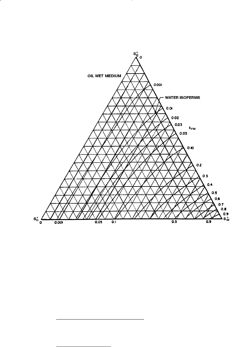
The triangular graph paper is commonly used to illustrate the changes in
the relative permeability values when three phases are flowing simultane-
ously, as illustrated in Figures 5-10 and 5-11. The relative permeability
data are plotted as lines of constant percentage relative permeability (oil,
water, and gas isoperms). Figures 5-10 and 5-11 show that the relative per-
meability data, expressed as isoperms, are dependent on the saturation val-
ues for all three phases in the rock.
Relative Permeability Concepts 311
Reservoir Eng Hndbk Ch 05 2001-10-24 09:52 Page 311

Three-Phase Relative Permeability Correlations
Honarpour, Keoderitz, and Harvey (1988) provided a comprehensive
treatment of the two- and three-phase relative permeabilities. The authors
listed numerous correlations for estimating relative permeabilities. The
simplest approach to predict the relative permeability to the oil phase in a
three-phase system is defined as:
k
ro
= k
row
k
rog
(5-44)
There are several practical and more accurate correlations that have
developed over the years, including:
• Wyllie’s Correlations
• Stone’s Model I
• Stone’s Model II
• The Hustad-Holt Correlation
312 Reservoir Engineering Handbook
Figure 5-10. Three-plate relative permeability imbibition. (After Honarpour et al., 1988.)
Reservoir Eng Hndbk Ch 05 2001-10-24 09:52 Page 312

Wyllie’s Correlations
Wyllie (1961) proposed the following equations for three-phase rela-
tive permeabilities in a water-wet system:
In a cemented sandstone, Vugular rock, or oolitic limestone:
k
SS S S
S
ro
owo wc
wc
=
+-
-
3
4
22
1
()
()
(5 - 46)
k
SS SSS
S
rg
gwcwowc
wc
=
--+-
-
22 2
4
1
1
[( ) ( ) ]
()
(5 - 45)
Relative Permeability Concepts 313
Figure 5-11. Three-phase drainage. (After Honarpour et al., 1988.)
Reservoir Eng Hndbk Ch 05 2001-10-24 09:52 Page 313

In unconsolidated, well-sorted sand:
Stone’s Model I
Stone (1970) developed a probability model to estimate three-phase
relative permeability data from the laboratory-measured two-phase data.
The model combines the channel flow theory in porous media with prob-
ability concepts to obtain a simple result for determining the relative per-
meability to oil in the presence of water and gas flow. The model
accounts for hysteresis effects when water and gas saturations are chang-
ing in the same direction of the two sets of data.
The use of the channel flow theory implies that water-relative perme-
ability and water-oil capillary pressure in the three-phase system are func-
tions of water saturation alone, irrespective of the relative saturations of
oil and gas. Moreover, they are the same function in the three-phase sys-
tem as in the two-phase water-oil system. Similarly, the gas-phase relative
permeability and gas-oil capillary pressure are the same functions of gas
saturation in the three-phase system as in the two-phase gas-oil system.
Stone suggested that a nonzero residual oil saturation, called minimum
oil saturation, S
om
exists when oil is displaced simultaneously by water
and gas. It should be noted that this minimum oil saturation S
om
is differ-
ent than the critical oil saturation in the oil-water system (i.e., S
orw
) and
the residual oil saturation in the gas-oil system, i.e., S
org
. Stone intro-
duced the following normalized saturations:
k
SSSS
S
rg
owowc
wi
=
+-
-
()( )
()
34
4
22
1
(5 - 50)
k
S
S
ro
o
wc
=
-
()
()
3
3
1
(5 - 49)
k
SS
S
rw
wwc
wi
=
-
-
Ê
Ë
Á
ˆ
¯
˜
1
3
(5 - 48)
k
SS
S
rw
wwc
wc
=
-
-
Ê
Ë
Á
ˆ
¯
˜
1
4
(5 - 47)
314 Reservoir Engineering Handbook
Reservoir Eng Hndbk Ch 05 2001-10-24 09:52 Page 314

The oil-relative permeability in a three-phase system is then defined as:
k
ro
= S
*
o
b
w
b
g
(5-54)
The two multipliers b
w
and b
g
are determined from:
where S
om
= minimum oil saturation
k
row
= oil relative permeability as determined from the oil-water
two-phase relative permeability at S
w
k
rog
= oil relative permeability as determined from the gas-oil
two-phase relative permeability at S
g
The difficulty in using Stone’s first model is selecting the minimum oil
saturation S
om
. Fayers and Mathews (1984) suggested an expression for
determining S
om
.
S
om
=aS
orw
+ (1 -a) S
org
(5 - 57)
with
a=1 -
S
g
1 -S
wc
- S
org
(5 - 58)
b
g
rog
g
k
S
=
-1
*
(5 - 56)
b
w
row
w
k
S
=
-1
*
(5 - 55)
S
S
SS
g
g
wc om
*
()
=
--1
(5 - 53)
S
SS
SS
for S S
w
wwc
wc om
wwc
*
()
,=
-
--
≥
1
(5 - 52)
S
SS
SS
for S S
o
oom
wc om
oom
*
()
,=
-
--
≥
1
(5 - 51)
Relative Permeability Concepts 315
Reservoir Eng Hndbk Ch 05 2001-10-24 09:52 Page 315

where S
orw
= residual oil saturation in the oil-water relative
permeability system
S
org
= residual oil saturation in the gas-oil relative permeability
system
Aziz and Sattari (1979) pointed out that Stone’s correlation could give
k
ro
values greater than unity. The authors suggested the following nor-
malized form of Stone’s model:
where (k
ro
)
Swc
is the value of the relative permeability of the oil at the
connate water saturation as determined from the oil-water relative per-
meability system. It should be noted that it is usually assumed that k
rg
and krog curves are measured in the presence of connate water.
Stone’s Model II
It was the difficulties in choosing S
om
that led to the development of
Stone’s Model II. Stone (1973) proposed the following normalized
expression:
This model gives a reasonable approximation to the three-phase rela-
tive permeability.
The Hustad-Holt Correlation
Hustad and Holt (1992) modified Stone’s Model I by introducing an
exponent term n to the normalized saturations to give:
kk
k
k
k
k
k
kkk
ro ro
S
wc
row
ro
S
wc
rw
rog
ro
S
wc
rg rw rg
=
(
)
(
)
+
Ê
Ë
Á
Á
ˆ
¯
˜
˜
È
Î
Í
Í
(
)
+
Ê
Ë
Á
Á
ˆ
¯
˜
˜
-+
(
)
˘
˚
˙
˙
˙
(5 - 60)
k
S
SS
kk
k
ro
o
wg
row rog
ro S
wc
=
--
Ê
Ë
Á
ˆ
¯
˜
*
*
*
()()
()
11
(5 - 59)
316 Reservoir Engineering Handbook
Reservoir Eng Hndbk Ch 05 2001-10-24 09:52 Page 316

where
The b term may be interpreted as a variable that varies between zero
and one for low- and high-oil saturations, respectively. If the exponent n
is one, the correlation is identical to Stone’s first model. Increasing n
above unity causes the oil isoperms at low oil saturations to spread from
one another. n values below unity have the opposite effect.
Example 5-5
Two-phase relative permeability tests were conducted on core sample
to generate the permeability data for oil-water and oil-gas systems. The
following information is obtained from the test:
S
gc
= 0.10 S
wc
= 0.15
S
orw
= 0.15 S
org
= 0.05
(k
ro
)S
wc
= 0.88
At the existing saturation values of S
o
= 40%, S
w
= 30%, and S
g
= 30%
the two-phase relative permeabilities are listed below:
k
row
= 0.403
k
rw
= 0.030
S
SS
SSS
w
wwc
wc om gc
*
=
-
---1
(5 - 65)
S
SS
SSS
g
ggc
wc om gc
*
=
-
-- -1
(5 - 64)
S
SS
SSS
o
oom
wc om gc
*
=
-
---1
(5 - 63)
b=
--
*
**
S
SS
o
wg
()()11
(5 - 62)
k
kk
k
ro
row rog
ro S
wc
n
=
È
Î
Í
Í
˘
˚
˙
˙
()
()b (5 - 61)
Relative Permeability Concepts 317
Reservoir Eng Hndbk Ch 05 2001-10-24 09:52 Page 317
