Stevenson J. Power system analysis
Подождите немного. Документ загружается.


366 CHAPTER 9 POWER-FLOW SOLUTIONS
the bus admittance equation
[ ;j:: 1 � �
[
-� -� ][ �: 1 �
[-jlO
W jlO
w
-;:� 1 [�: 1
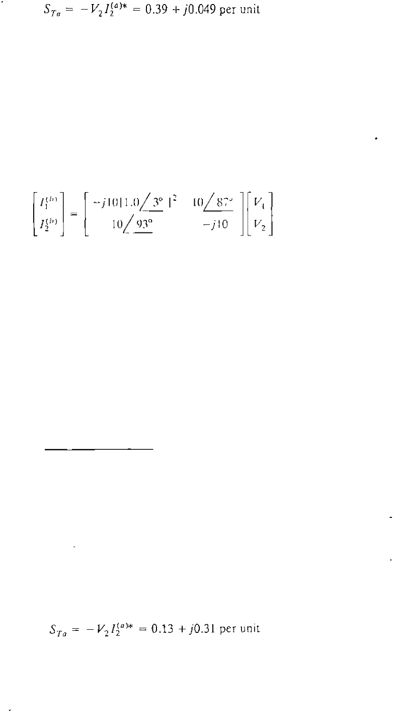
and the currents in transformer T" with ( = LOS, as shown in Fig. 9.11, are given
by Eq. (9.74), which takes the numerical form
[-j11.025
W j10.500
w
j
1
0 JOO 1 [VV21 1
-j10.000
In F
i
g
.
9.11 current 11 = (f�
a
) +
I}b», and likewise, 12 = (Jia)
+ lib», whi ch
means that the preceding two mat rix equations can be directly added (like
admittances in pallel) to obtain
[
I
I
]
= [
-
j21 .025
12
@ j20.500
W
j20 .500
]
[
V
I
]
-j20.000
V
2
In Example 2.13 V
2
is the reference voltage 1.0 and the current 12 is
calculated to be - 0.8 + jO.6. Therefore, [rom the second row of the preceding
equation we have
12 = -0.8 +jO.6 =j20.5V1 -j20(1.0)
which gives the per-unit voltage at bus
-0.8
+
j20.6
V
=
--
I
j20.5
1.0049
+ jO.0390 per unit
Since V
I
and V
2
are now both known, we can return to the admittance equation
fo r transformer Ta to obtain
I
i
a
) =
jlOV1 - jl0V
2
=
j10(1.0049 + jO.0390 - 1.0)
= - 0.390 + jO.049 per unit
and from the admittance matrix for transformer T"
l�
b
) = j10.5VI - j10V2 = j10.5
(
1.0049 + jO.0390) - jlO
= -0.41 + jO.55 Lper unit
9.6 REGULATING TRANSFORMERS 367
Hence, the complex power outputs of the transformers are
5
T
b
=
- V2Iib)*
=
0.41
+
j0.551 per unit
The results found by the approximate circulating current method of Example 2.13
compare favorably with the above exact solution.
Example 9.8. Solve the phase-shifter problem of Example 2.14 by the exact
Y
bus
model of Eq. (9.74) and compare results.
Solution. The bus admittance equation for the phase-shifting tra nsformer Tn with
I = Ej
- 2008 — 2025 «СтудМед»