Simmons C.H., Dennis E.M. Manual of Engineering Drawing
Подождите немного. Документ загружается.

260 Manual of Engineering Drawing
attached by set screws to the shaft end (b). The outer
ring is normally retained by the housing end cover (c),
but a threaded ring screwed into the housing bore is
sometimes used (d).
Instead of shaft or housing abutment shoulders, it is
frequently convenient to use spacing sleeves or collars
between the bearing rings (e), or a bearing ring and
the adjacent component, e.g. a gear (f). On shafts,
location can also be achieved using a split collar which
seats in a groove in the shaft and is retained by either
a solid outer ring which can be slid over it, or by the
inner ring of the bearing itself.
Axial location of rolling bearings by means of snap
rings can save space, assist rapid mounting and
dismounting and simplify machining of shaft and
housings. An abutment collar should be inserted between
the snap ring and the bearing if heavy loads have to be
carried, in order that the snap ring is not subjected to
large bending moments across its section. If required,
the axial clearance, which is generally present between
the snap ring and the snap ring groove can be reduced
by selecting an abutment collar of suitable width or by
using shims. Deep groove ball bearings with a snap
ring groove in the outer ring and fitted with a snap
ring sometimes provide a simplified and compact
housing arrangement.
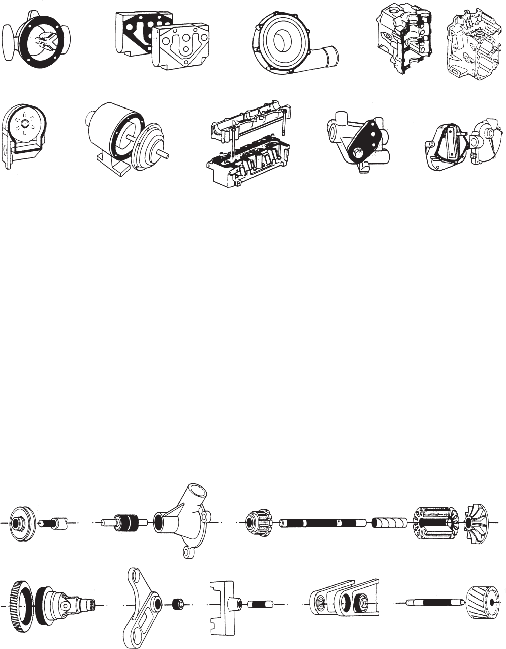
Bearings with a tapered bore mounted directly on
tapered shafts are usually retained by a locknut on the
shaft (g), or the locknut may be screwed on to an
externally threaded split ring inserted into a groove in
the shaft (h). With adapter sleeve mounting, the locknut
positions the bearing relative to the sleeve ( j). When
bearings with an adaptor sleeve are mounted on shafts
without an abutment shoulder, the axial load which
can be applied depends on the resulting friction between
shaft and sleeve. When bearings with a tapered bore
are mounted on withdrawal sleeves the inner ring of
the bearing must be mounted against an abutment (k).
A suitable abutment can be provided by a collar which
can frequently serve as part of a labyrinth seal. The
withdrawal sleeve must be secured in position
either by means of a locknut or an end plate and set
screws.
Seals
Bearings must be protected by suitable seals against
the entry of moisture and other contaminants and to
prevent the loss of lubricant. The effectiveness of
the sealing can have a decisive effect on the life of a
bearing.
Many factors must be considered when deciding on
the best sealing arrangements for a given bearing
application, e.g. the type of lubricant (oil or grease),
peripheral speed at the sealing surface, misalignment
of the shaft, available space, friction of the seal and
resultant temperature rise and cost. Two basic designs
are normally used for rolling bearings.
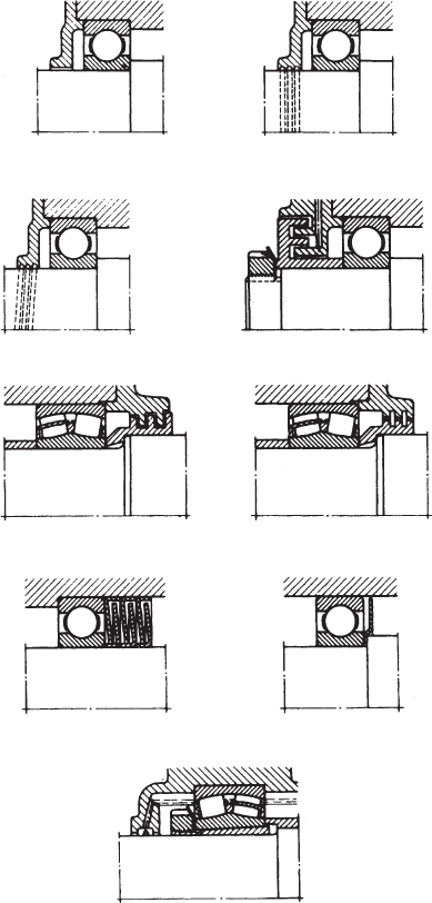
Non-rubbing seals (Fig. 28.22)
Non-rubbing seals depend for their effectiveness on
the sealing efficiency of narrow gaps, which may be
arranged axially, radially or combined to form a
labyrinth. This type of seal has negligible friction and
wear and is not easily damaged. It is particularly suitable
for high speeds and temperatures.
(a)
(b)
(c) (d)
(e) (f)
(g) (h)
(i)
Fig. 28.22
This simple gap type seal which is sufficient for
machines in a dry, dust free atmosphere comprises a
small radial gap formed between the shaft and housing
(a). Its effectiveness can be improved by providing
one or more grooves in the bore of the housing cover
(b). The grease emerging through the gap fills the
grooves and helps to prevent the entry of contaminants.
With oil lubrication and horizontal shafts, right or left
hand helical grooves can be provided in the shaft or
Bearings and applied technology 261
the seal bore (c). These serve to return any oil which
may tend to leak from the housing. However, with this
arrangement it is essential that the direction of rotation
does not vary.
Single or multiple labyrinths give appreciably more
effective sealing than gap seals but they are generally
more expensive to manufacture. They are chiefly used
with grease lubrication. Their effectiveness can be still
further improved by providing a grease duct connecting
with the labyrinth passage and periodically pumping
in a quantity of water insoluble grease, e.g. a calcium
soap base grease. In solid housings the tongues of the
labyrinth seal are arranged axially (d), and in split
housing, radially (e). The radial clearance between the
shaft and the housing seal components is not affected
by axial displacement of the shaft during running and
can be made very small. If angular misalignment of
the shaft relative to the housing has to be accommodated,
labyrinths of the form shown at (f) are normally used.
An inexpensive and effective labyrinth seal can be
made using pressed steel sealing washers (g). The
effectiveness of this type of seal increases in direct
proportion to the number of washers used. To increase
the sealing efficiency of non rubbing seals, the shaft
can be fitted with rotating discs (h) and in case of oil
lubrication, flinger rings (i) are often used. The oil
flung from the ring is collected in a channel in the
housing wall and returned to the sump through suitable
ducts.
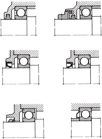
Rubbing seals (Fig. 28.23)
Rubbing seals rely for their effectiveness essentially
on the elasticity of the material exerting and maintaining
a certain pressure at the sealing surface. The choice of
seal and the required quality of the sealing surface
depend on the peripheral speed.
Felt washers (a) are mainly used with grease
lubrication, e.g. in plummer blocks. They provide a
simple seal suitable for peripheral speeds up to 4 m/s
and temperatures of about 100°C. The effectiveness of
the seal is considerably improved if the felt washer is
supplemented by a simple labyrinth ring (b). The felt
washers or strips should be soaked in oil at about 80°C
before assembly.
Where greater demands are made on the effectiveness
of the rubbing seal, particularly for oil lubricated
bearings, lip seals are often used in preference to felt
seals. A wide range of proprietary lip type seals is
available in the form of ready to instal units comprising
a seal of synthetic rubber or plastics material normally
enclosed in a sheet metal casing. They are suitable for
higher peripheral speeds than felt washers. As a general
guide at peripheral speeds of over 4 m/s the sealing
surface should be ground, and above 8 m/s hardened
or hard chrome-plated and fine ground or polished if
possible. If the main requirement is to prevent leakage
of lubricant from the bearing then the lip should face
inwards (c). If the main purpose is to prevent the entry
of dirt, then the lip should face outwards (d).
The V-ring seal (e) can be used for grease or oil
lubricated bearing arrangements. It comprises a rubber
ring with a hinged rubber lip which is pressed axially
against the sealing surface. It is easy to fit, can
accommodate fairly large angular misalignments of
the shaft relative to the housing at slow speeds, and in
certain circumstances is suitable for high speeds. The
effectiveness of the seal owes much to the fact that
dirt and liquids tend to be flung off by the rotating
seal. The V ring seal is normally fitted on the inside
rotating seal. The V ring seal is therefore normally
fitted on the outside of the housing when grease
lubrication is used and on the inside with oil lubrication.
Spring steel sealing washers provide a cheap and
space saving seal, especially for grease lubricated deep
groove ball bearings. They can either be clamped against
the outer ring (f) or against the inner ring and are
designed so that the sealing face is constrained to press
against the face of the other bearing ring.
Combined seals
In difficult operating conditions and where severe
demands are placed on sealing, e.g. large amounts of
dirt or water, rubbing and non rubbing seals are often
combined. In such cases the non rubbing seals
(labyrinths, flinger rings, etc.) are arranged to
supplement the rubber seals and protect them from
wear.
Sealed and shielded bearings
Simple space saving arrangements can be achieved by
using bearings incorporating seals or shields at one or
(a) (b)
(c) (d)
(e) (f)
Fig. 28.23
262 Manual of Engineering Drawing
both sides which are supplied lubricated with the correct
quantity of grease. Relubrication is not normally
required and they are primarily intended for applications
where sealing is otherwise inadequate or where it cannot
be provided for reasons of space.
Lubrication
Grease lubrication is generally used where ball and
roller bearings operate at normal speeds, temperature
and loading conditions. Grease has certain advantages
by comparison with oil: it is more easily retained in
the bearing housing and assists in sealing against the
entry of dirt and moisture.
In general the free space in the bearing and housing
should only be partly filled with grease (30 to 50%).
Overfilling causes rapid temperature rise particularly
if speeds are high. Manufacturers supply details
regarding suitable weights of grease for particular
bearings.
Bearings can be supplied which are sealed after
prepacking with the correct type and quantity of grease.
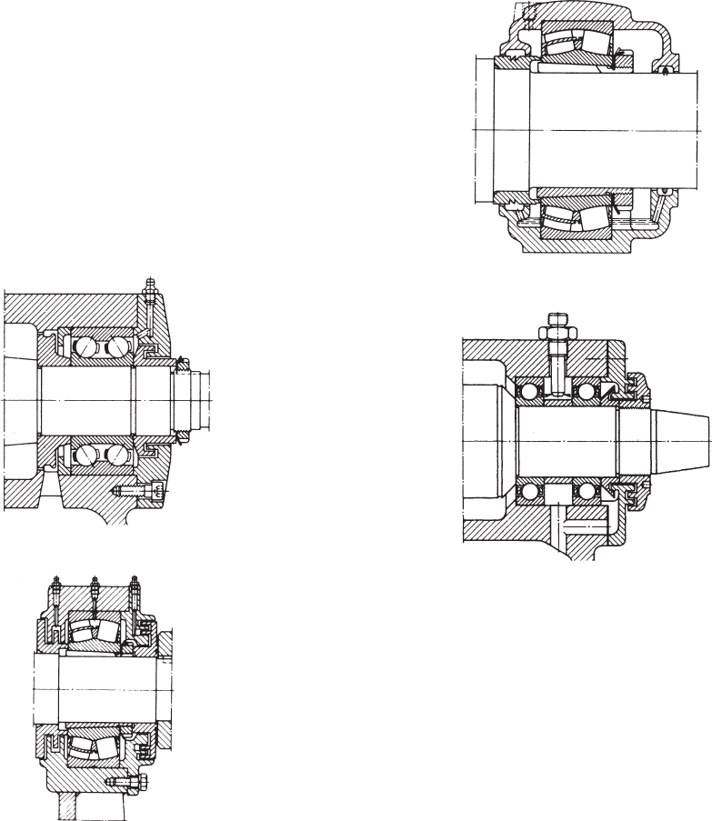
Where relubrication is more frequent, provision must
be made by fitting grease nipples to the housing. Grease
will then be applied by a grease gun and a lubrication
duct should feed the grease adjacent to the outer ring
raceway or between the rolling elements. Examples
are shown in Fig. 28.24.
Oil lubrication
Oil lubrication is generally used where high speeds or
operating temperatures prohibit the use of grease, when
it is necessary to transfer frictional heat or other applied
heat away from the bearing, or when the adjacent
machine parts, e.g. gears, are oil lubricated.
Oil bath lubrication is only suitable for slow speeds.
The oil is picked up by rotating bearing elements and
after circulating through the bearing drains back to the
oil bath. When the bearing is stationary the oil should
be at a level slightly below the centre of the lowest
ball or roller. An application is shown in Fig. 28.25. At
high speeds it is important that sufficient oil reaches
the bearing to dissipate the heat generated by friction
and oil jets provide an effective method (Fig. 28.26).
Fig. 28.24
Fig. 28.25
Fig. 28.26
The illustrations in this section (Figs 28.10 to 28.26)
are reproduced by kind permission of SKF (U.K.)
Limited Bradbourne Drive, Tilbrook, Milton Keynes,
MK7 8BJ.
Trouble-Free Bearing Operation
When bearings fail, they can bring equipment to an
unscheduled halt. Every hour of downtime due to
premature bearings failure can result in costly lost
production in a capital intensive industry. Substantial
Bearings and applied technology 263
investment in research and development has resulted
in the manufacture of bearings of the highest quality.
Quality alone cannot guarantee trouble-free bearing
operation since other factors may affect life span
including the following:
1 Operating environment Machinery must be kept
in peak operating condition. Bearings should be
properly aligned and protected from extreme
temperatures, moisture and contaminants.
2 Proper installation Knowledge of the proper
installation techniques and tools is required to ensure
that the bearings are not damaged.
3 Proper maintenance Following lubrication and
maintenance schedules using recommended
materials and time intervals is essential. A familiarity
with operating procedures, basic trouble shooting,
condition monitoring and vibration analysis is also
desirable.
However, bearing manufacturers do have a full line of
products and services to make installation and
maintenance easy to perform and should be consulted.
This will certainly contribute to long bearing life and
ensure cost effective operation.
General convention and
simplified representation
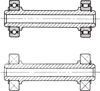
Both types are illustrated in Figure 28.27.
Fig. 28.27
Ball and roller bearings
Former simplified
representation
Simplified representations for both types are the
same. The simplification shown here with crossed
diagonal lines was the practice used by industry in the
past.
Current practice introduces a free standing upright
cross referred to in ISO 8826-1.
The use of adhesives is now a well established practice
in manufacturing. New materials and production
processes have considerably increased the options
available to the engineering designer. Adhesive bonding
is a proved cost effective manufacturing method and
can be used with confidence. A basic principle is
however that joints should be designed with this method
of production in mind when the product is in the early
stages of development.
The following are some advantages of using
adhesives:
(a) Stress concentrations present in bolted, riveted or
spot welded joints are avoided.
(b) The distribution of stresses achieved by adhesive
bonding permits a reduction in weight and cost.
Especially relevant with fragile materials and light-
weight structures. Joint strength and fatigue
properties are improved.
(c) Production costs are reduced due to the elimination
of drilled holes and other machining operations.
Labour costs are reduced with automated assembly
work.
(d) Structures are generally stiffer despite weight
reduction since the bonding covers the whole area
of the join. Rivets, screws and spot welds pin the
surfaces together only at localized points. Loading
may be increased before buckling occurs.
(e) Gap filling properties. Certain adhesives are gap
filling, and this makes possible the continuous
joining of materials where the gap along the joint
is of irregular width.
(f) Delicate or brittle materials such as metal foils or
ceramics are readily bonded.
(g) High strength bonds can be formed at room
temperature with minimal pressure by using cold-
setting adhesives.
(h) The film formed by the adhesive resists corrosion,
can form a leak-proof seal and insulate dissimilar
metals against electrochemical action.
Designing for adhesives
For the best possible performance, joints should be
specifically designed for adhesive bonding. Follow this
principle and much better joints will be achieved than
if bonding is adopted as a substitute for welding in a
joint designed for that purpose. Bond stresses, materials,
type of adhesive, surface preparations, method of
application and production requirements can then all
be considered in relation to each other at the outset.
The designer should consider especially the effect of
shear, tension, cleavage and peel stresses upon the
joint. Bonded joints perform best under conditions of
tension (pure), compression or shear loading; less well
under cleavage; and relatively poorly under peel loading.
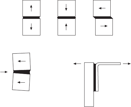
The loading conditions are shown in Fig. 29.1.
Designing a joint to take pure tensile or compressive
stresses is normally impracticable with sheet materials,
so all joints in sheet materials should be designed so
that the main loading is in shear. Joints between massive
parts perform well in tension or compression loading,
provided this is uniform – a side load may set up
excessive cleavage stresses in a tension-loaded bond.
(Fig. 29.1(d)). Cleavage loading will concentrate stress
at one side of the joint. Bond area may have to be
increased to withstand this load so the joint will not
prove so economical in terms of material and/or
adhesives as joints designed for shear and tension
stresses. Peel strength is usually the weakest property
of a joint. A wide joint will be necessary to withstand
peel stresses, plus the use of an adhesive with high
peel strength.
For an adhesive to be used, a joint must allow the
easy application of the adhesive, must allow for the
Chapter 29
Engineering adhesives
(a) (b) (c)
(d)
(e)
Fig. 29.1 Loading conditions.
(a) Tension (b) Compression
(c) Shear (d) Cleavage
(e) Peel
Engineering adhesives 265
adhesive to cure fully, and must be designed to give
uniform stress. Even in a simple face-to-face joint it
must be possible to apply adhesive to one surface and
for it to remain there until the two parts are brought
together and after that until curing takes place.
These requirements highlight the need for a choice
of thin, thick or thixotropic adhesives. Design details
which may also be significant include removal of sharp
edges and substitution of a bevel or radius.
The bond line
The gap between the parts, and therefore the thickness
of the adhesive film, has an important bearing on the
characteristics of the joint. In terms of simple strength
a thick bond line will generally be a weakening feature,
since the mechanical strength of the unsupported resin
film is likely to be less than that of the substrates.
A thick bond line can however confer advantages.
The adhesive is generally more flexible than the
adherents or substrates. This is particularly so in most
engineering applications where metals or other rigid
materials can be bonded. Because of this, a thick bond
line can offer a capacity to absorb some impact energy,
thus increasing the strength of the bond under this
type of loading.
Consideration of bond line thickness leads
immediately to the question of environmental resistance.
Adhesive bonds will always be susceptible to
environmental attack and it is essential that any such
attack should not reduce the strength of the bond to an
unacceptable level. The most important factor here is
the correct choice of adhesive, but design of the joint
can make a significant difference. Thus a thick bond
line offers a ready path for access by moisture or other
solvents which might be able to diffuse through the
cured adhesive.
Typical bonded joints
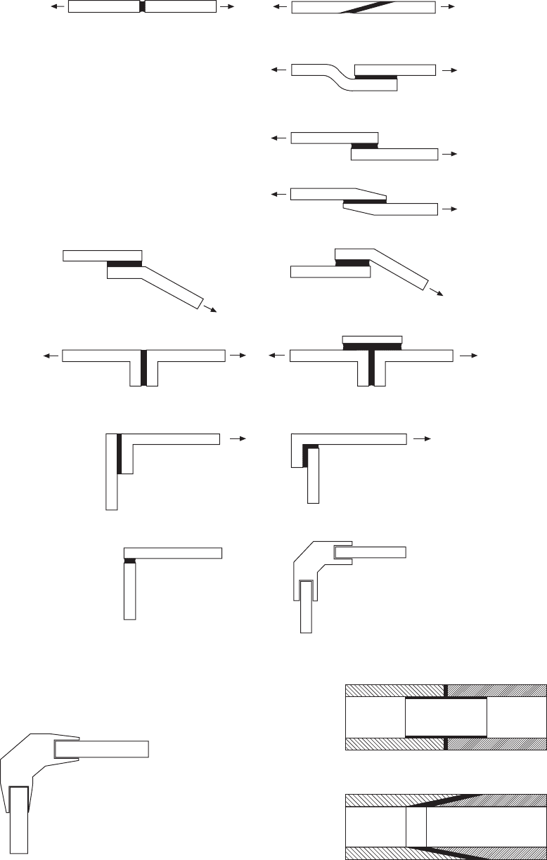
Figure 29.2 shows a range of bonded joints and possible
modifications which can be made to reduce or eliminate
the effect of cleavage and peel stresses.
The following notes should be regarded as of a
general nature.
(a) Avoid butt joints if bond area is small.
(b) Scarfed joint provides increased bonding area.
(c) Simple lap joint with in-line forces.
(d) Alternative lap joint with offset loading.
(e) Tapered lap joint.
(f) Bracket bonded to a fixed surface where peel is
likely.
(g) Repositioned bracket strengthens joint.
(h) and (j) Cleavage loading eliminated by the addition
of a component in shear.
(k) and (l) Simple improvement for safety.
(m) and (n) Increase in bond area reinforces corner
joint.
Quite obviously practical considerations involve a study
of the forces applicable and acceptable appearance of
the finished assembly.
Figure 29.4 shows two tubular applications.
In (a), a cylindrical plug is used to join two tubes in
a structure. An example of a tapered tubular joint is
given in (b). The taper ensures that the adhesive is not
pushed out of the assembly.
The joint permits a long bond line and does not
impede fluid flow.
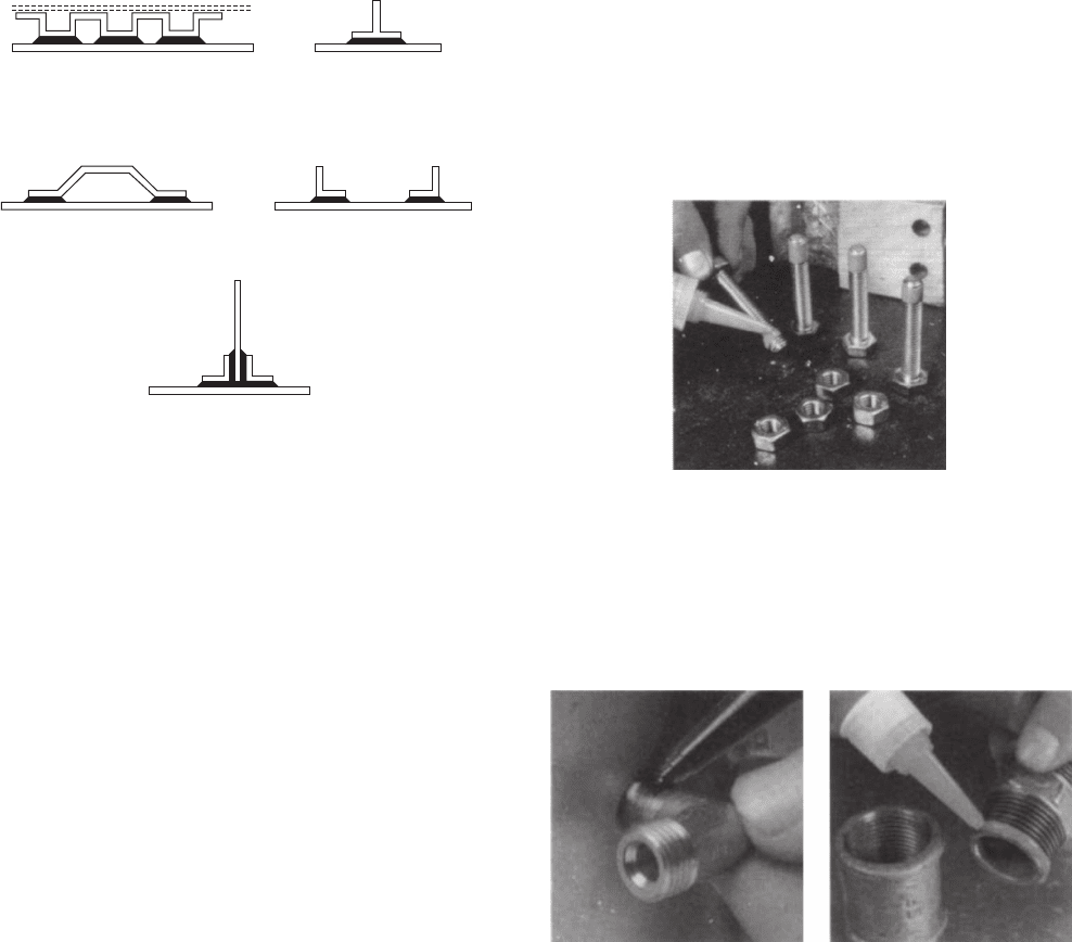
A selection of bonded stiffeners are shown in Fig.
29.5. These can be used to reduce vibration and
deflection of thin sheet materials. When the flanges
on the stiffened sections do deflect with the sheet,
little difficulty from peel results due to the area of the
bond. Corrugated backings can provide complete
flatness over the entire area. If a corrugated insert is
sandwiched between two flat sheets (the second sheet
is indicated by dotted lines) as indicated in example
(a) then a structure of lightweight and high strength
can be manufactured from adhesive bonding. There
are many aircraft applications. Standard strip, angles,
tee sections and formed channels are used in structural
engineering.
The types of adhesive which cover the vast majority
of engineering assembly applications come from the
following categories.
1 Epoxies Two components are mixed in equal
proportions. The adhesive and the hardener begin
to cure immediately and have a usable ‘pot life’.
After this time the bond becomes less effective.
Often used for DIY repairs. Industry uses an
alternative type of epoxy which incorporates rubber
of low molecular weight and is called a toughened
adhesive. It has greater resistance to impact forces
and peel.
This is a single component epoxy which is
hardened by heat curing while the parts being bonded
are clamped.
Used to bond composite materials, tubular frames
and in the manufacture of components for double
glazing assemblies.
2 Acrylic adhesives Four basic types:
(a) Toughened acrylics. These are two-part systems
where a hardener and an adhesive are applied to
the two surfaces being joined and the assembly
of the joint automatically mixes them. Can be
used on oily steel. Will bond glass into metal
frames. Also used in railway carriage interior
panels.
(b) Cyanoacrylate adhesives polymerize (solidify) by
a chemical reaction which is usually initiated by
atmospheric moisture, present as traces of water
on the surfaces to be joined. Successful bonding
depends upon ambient humidity, the type of
material being bonded, the choice of adhesive,
and the nature of the surface.
‘Instant adhesives’ and ‘Superglues’ are in this
range of products.
266 Manual of Engineering Drawing
Poor design
(a)
(b)
(c)
(d)
(e)
(f)
(g)
(h) (j)
(k)
(l)
(m)
(n)
Improved design
Fig. 29.2 Typical bonded joints
(a)
(b)
Fig. 29.3 Where slotted joints are used, tapering removes the high
stress concentrations caused by abrupt changes in section. Example
gives a possible modification to Fig. 29.2(n)
Fig. 29.4
Engineering adhesives 267
(c) Anaerobic adhesives automatically harden in the
absence of air and are used mainly in rigid metallic
joints. Many applications follow. These products
are manufactured normally as single component
materials.
(d) UV curing acrylics are single component adhesives
where cure is effected rapidly by placing the
assembly under an ultra violet lamp.
These adhesives are applied in the manufacture
of printed circuit boards for surface sealing.
3 Hot melt adhesives are available in rod, sheet and
powder forms. A convenient method of assembling
small components which are lightly loaded. A heating
gun raises the temperature of the rod and the adhesive
is applied to one component. On cooling, the adhesive
solidifies and the two surfaces are bonded together.
These adhesives are also used in packaging
equipment.
4 Solvent based contact adhesives. Here the adhesive
is applied in a solvent solution to the two surfaces.
The solvent evaporates leaving a tacky film and the
surfaces are brought together. Applications include
laminated sheet fixings in furniture manufacture.
A considerable range of options is available to the
designer in the choice of suitable types of adhesive.
Precision measuring and dispensing is necessary so
that the required volume, in the defined position, is
applied at a given time and with consistently repeatable
accuracy on a production line.
In the interests of satisfactory selection and operation,
it is recommended that the manufacturer should be
consulted to ensure that all technical considerations
have been included in a proposed scheme.
Engineering applications
The following examples show varied uses of engineering
adhesives in industry.
Locking screw threads The liquid is applied to the
cleaned thread of a bolt or stud. When the nut is
tightened the liquid fills the gaps between mating threads
and hardens to form a tough plastic joint which is
shock, vibration, corrosion and leak proof. The joint
will remain in place until it needs to be undone again
using normal hand tools.
Fig. 29.5
(a)
(b)
(c)
(d)
(e)
Fig. 29.6 Thread locking
Threadsealing pipe fittings The sealant is applied to
the clean thread and screwed together as normal. The
sealant will not creep or shrink and gives a constant
and reliable seal. There is no need to wrench tight and
the fitting can be positioned as required.
Fig. 29.7 Thread sealing
(a) Hydraulic sealant for fine threads in pneumatic and hydraulic
systems – particularly those subject to vibration
(b) Pipe sealant used to seal coarse threads of pipes and fittings up to
75 mm outside diameter
Retaining Traditional retaining methods using screws,
splines, pins, keys and press fits, etc, do not necessarily
seal joints and eliminate the possibility of corrosion.
Local stress concentrations may cause cracking.
Retaining adhesives can be used to augment these
methods. Often, a redesign will give a replacement
with substantial cost savings.
These adhesives are supplied in various strengths:
(a) High shear strength adhesives in association with
press fits can provide added rigidity.
(b) Maximum strength retainers are used on parts which
generally do not need to be taken apart.
(c) Medium strength adhesives suit parts which need
frequent disassembly.
268 Manual of Engineering Drawing
Sealing with anaerobic gaskets Gaskets are fitted
between flanges to provide an effective seal against
fluids and gases. It is cheaper to use a gasket than
manufacture two perfectly flat mating surfaces with
close flatness and surface finish tolerances.
Gaskets can be preformed from materials such as
compressed asbestos, paper, fibre or cork. Alternatively,
they can be formed where they are required with a
liquid.
The principles of liquid gasketing are fundamentally
different to preformed gaskets in that they allow metal
to metal contact. There are several forms of liquid
gasket such as anaerobic, non setting solvent based
and moisture curing.
The anaerobic principle Anaerobic gaskets are
available in a range of viscosities from thick liquids to
non slump pastes. Each can be applied directly from
the original container, or by various application methods
such as simple rollers, screen printing and computerized
robotics. On assembly, the anaerobic gasket spreads
between the flanges and is forced into surface
irregularities to provide total contact between the two
faces. The product then polymerizes at ambient
temperaure into a tough thermoset plastic.
The strength of joints from anaerobics can be tailored
to suit a specific application. Effective cure requires
the absence of air and the presence of metal. At room
temperature it takes just a few minutes.
Note. Anaerobic gaskets are thermosetting plastics;
the temperature range in service can be from – 50°C
up to 200°C at the joint line. They seal against petroleum
based fuels and lubricating oils, water/glycol mixtures
and many other industrial chemicals. For compatibility
of specific chemical environments the designer would
be advised to consult the manufacturers.
Although anaerobic gaskets permit metal to metal
contact, electrical continuity cannot be assumed.
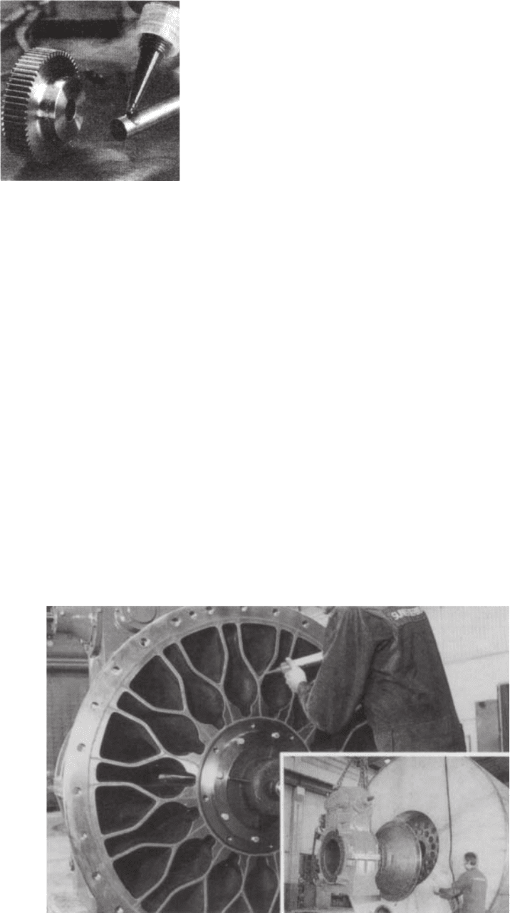
Figure 29.9 shows the application of an anaerobic
gasket to the backplate of a large diesel engine.
The flow of adhesive to the work surface is regulated
by manual control of the air supply to a pneumatic
cartridge gun.
It often happens during maintenance work that
damaged or scored surfaces are found and an adhesive
gasket can save the need and cost of remachining.
Engineering adhesives for sealing flat faces have
the following characteristics and applications.
(a) They will seal on horizontal, vertical and overhead
flanges and accommodate surface irregularities of
up to 0.5 mm.
(b) Low strength products are available for close fitting
surfaces which will be frequently dismantled.
(c) In the illustrations below (Fig. 29.10) many of the
components are manufactured in aluminium alloys.
The structural integrity of an assembly can be
enhanced by the use of high shear strength
adhesives.
Fig. 29.8 Retaining
Fig. 29.9
Engineering adhesives 269
Engineering adhesives for retaining cylindrical
assemblies have the following characteristics and
applications:
(a) The retention of shafts and rotors of electric motors,
gears, pulleys, sleeves, bushes and oil seals in
housings.
(b) The ability to withstand fatigue and augment
torsional strength.
(c) Suitable for parts that need easy disassembly, such
as bearings on shafts and in housings, bushes and
journals in soft metals.
(d) An oil-tolerant adhesive is available that gives high
strength retention of parts ‘as received’, i.e. no
cleaning is needed before assembly. Oil impregnated
bushes are retained with this grade. They are
manufactured by the sintering process.
(e) An adhesive can be recommended for continuous
working temperatures up to 175°C. It combines
the ability to fill gaps of up to 0.15 mm in diameter
with high shear strength and good solvent resistance.
Instant adhesives
As the name suggests, they work in seconds and are
ideal for bonding close fitting parts made from a variety
of materials. They offer advantages over other forms
of joining, such as plastic welding, two-part or heat-
cured adhesives and mechanical fasteners. The benefits
include faster assembly times, better appearance, less
outlay for capital equipment and these adhesives can
also be used to repair metal, plastic, rubber or ceramic
components which might otherwise be scrapped.
Instant adhesives are available for the following
applications:
(a) General purpose adhesive for plated metals,
composite materials, wood, cork, foam, leather,
paper – all surfaces which were once considered
‘difficult’ – can now be bonded quickly and
permanently.
(b) A special rubber and plastics adhesive ensures fast-
Fig. 29.10
Fig. 29.11