Short T.A. Electric Power Distribution Handbook
Подождите немного. Документ загружается.


568 Electric Power Distribution Handbook
vision. The perception process involves the thermal characteristics of the
filament and the human eye–brain response.
The European community has derived sophisticated methods of charac-
terizing and analyzing flicker, developing a flickermeter (IEC 868, 1986) and
a comprehensive set of standards. The IEEE is moving towards adopting the
European flickermeter approach to quantify flicker (Halpin et al.). The flick-
ermeter models the complex lamp–eye–brain interaction to uniformly quan-
tify flicker from a variety of sources, whether the offending load is an arc
furnace or repetitive motor starts. The flickermeter measures voltage and
produces these outputs:
• Instantaneous flicker sensation — This output is in “perception units,”
a unit-less quantity. One per unit is defined as the threshold of
perception for 50% of the population.
• Short-term flicker indicator (P
st
) — The short-term flicker indicator is
a weighted factor based on probabilities of the instantaneous flicker
sensation over a ten-minute monitoring period. A P
st
= 1 is the
threshold of irritation, the level that the majority of the population
finds annoying. P
st
values as low as 0.7 have been found to be visible
under some conditions.
• Long-term flicker indicator (P
lt
) — Long-term flicker is based on 2 h
of flicker measurement and combines 12 consecutive P
st
values
(using the cubed root of the sum of the cubes of the 12 P
st
values).
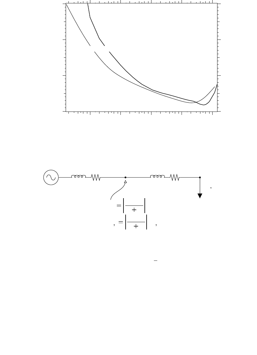
The flickermeter produces comparable results to the GE flicker curve when
the flickermeter has a square-wave input as shown in Figure 11.21. Both the
GE curve and the IEC curve (calibrated for 120-V lamps) produce comparable
results. A flicker curve analysis is easier for loads that fluctuate periodically
in a square-wave fashion. For intermittent or chaotic loads like welders, a
flicker curve is impossible to use. Converting a measured waveform to the
frequency domain with a Fourier transform and plotting the results on a
flicker curve is imprecise. While the exercise reveals predominant frequen-
cies, the Fourier transform does not mimic the brain’s response to flickering
light. The flickermeter is much more appropriate for cases where loads
fluctuate irregularly.
The P
st
is an rms quantity that we can treat like a per-unit voltage. If the
current draw from the fluctuating load doubles (and the waveshape stays
the same), the voltage deviation (DV) will double, and P
st
will double. Just
as we can use voltage dividers, we can use impedance dividers to estimate
flicker propagation and estimate flicker severity at other locations on a circuit
(see Figure 11.22). Flicker decreases as one moves upstream of the fluctuating
load on a radial circuit. Customers at or downstream of the fluctuating load
experience the worst flicker.
Multiple sources of harmonics can influence flicker differently, depending
on the characteristics of the fluctuating loads. Multiple sources combine as
1791_book.fm Page 568 Monday, August 4, 2003 3:20 PM
(C) 2004 by CRC Press LLC
Other Power Quality Issues 569
UIE, the organization that developed many of the European flicker stan-
dards (UIEPQ-9715, 1999), suggests the following values of m for combining
multiple fluctuating loads (smaller m is more conservative):
m = 4: for arc furnaces operated to avoid simultaneous operations
m = 3: when the risk of simultaneous voltage variations is minimal (Most
unrelated loads are in this category.)
FIGURE 11.21
GE borderline of irritation curve compared to the voltage change necessary to produce P
st
= 1
from the IEC flickermeter with a square-wave input.
FIGURE 11.22
Propagation of voltage flicker.
GE IEC
0.1 1.0 10.0 100.0 1000.
0
2
4
6
Voltage dips per minute
DV/V
%
Fluctuating
load
12
Z
1
Z
2
P
st
1
Z
1
Z
1
Z
2
P
st
2
DV
1
Z
1
Z
1
Z
2
DV
2
P
st
2
DV
2
PP
st TOTAL st i
m
m
,,
=
()
Â
1
1791_book.fm Page 569 Monday, August 4, 2003 3:20 PM
(C) 2004 by CRC Press LLC

570 Electric Power Distribution Handbook
m = 2: simultaneous operation of devices producing random-noise type
fluctuations, such as arc furnaces operating at the same time
m = 1: when there is a high probability of simultaneous operation
The flickermeter can effectively quantify flicker for existing loads; it does
not help much for predicting the flicker at new installations. It is possible to
model the time variations of fluctuating loads and run a software “flicker-
meter” on the results. If a similar load exists on the system, another approach
is to measure P
st
at the existing location and scale it by the relative differences
between impedances at the existing location and the new location:
where
P
st,A
= the short-term flicker indicator measured at a location with an
impedance back to the source of Z
A
(the three-phase short-circuit
impedance)
P
st, B
= the short-term flicker indicator for the same fluctuating load moved
to a point B which has a short-circuit impedance of Z
B
A basic screening criteria based on the stiffness of the distribution circuit
and the amount of fluctuation also helps determine if flicker could be a
problem at new installations. The Europeans have adopted a set of criteria
depending on the rate of change of the load and the fluctuation relative to
the stiffness of the supply (Table 11.5). The change in load (DI) is referenced
to the short-circuit current at the nearest customer (I
SC
). At less than ten
changes per minute, with a short-circuit level on the primary of 1000 A, a
load could fluctuate by 4 A (as measured on the primary) without causing
flicker if the fluctuations are fewer than 10/min. North American limits could
be less conservative than this because the lower-voltage North American
light bulb is less sensitive to flicker than filaments at higher European volt-
ages (120-V vs. 230-V bulbs).
Motor starts are a special case of voltage flicker. Most motors start only a
few times per day, which is possibly off the flicker curve. While motors may
TABLE 11.5
Thresholds Where Fluctuating Loads
Will Not Cause Flicker Problems per
(IEC 61000-3-7, 1995; UIEPQ-9715, 1999)
Number of Voltage changes
per minute, r DD
DD
I / I
SC
, %
r > 200 0.1
10 £ r £ 200 0.2
r < 10 0.4
P
Z
Z
P
st B
B
A
st A,,
=
1791_book.fm Page 570 Monday, August 4, 2003 3:20 PM
(C) 2004 by CRC Press LLC

Other Power Quality Issues 571
start infrequently, when they do start, the voltage change is sharp, and light
change can be deep and easily visible. Motors normally draw five to six times
full-load current during starting. Normally, the voltage drops suddenly and
then gradually recovers over several seconds as the motor comes up to speed.
Utilities normally have a criteria for motor starts based on the change of
voltage and how often the customer starts the motor. Willis (1997) reported
that many utilities use a criteria of 3% during motor starting (Table 11.6),
but some utilities vary on how they define the percentage (either relative to
the nominal voltage, the minimum voltage, or the voltage at the time of the
motor start). Also, utilities often limit the size of motors or the starting
current allowed by end users, depending on the voltage (see Table 11.7 for
one utility’s limits).
The source impedance at the customer with the motor (or other fluctuating
load) is an important component. As with harmonics, we are most concerned
TABLE 11.6
Voltage Flicker Limits at Several Utilities
during Motor Starting
Utility Voltage Criteria
Dense urban area 3%
Urban/suburban 3%
Suburban and rural 3%
Urban and rural 3%
Rural, mountainous 4 V (on a 120-V base)
Rural, mountainous none
Source: Willis, H. L., Power Distribution Planning
Reference Book, Marcel Dekker, New York, 1997.
TABLE 11.7
One Utility’s Allowable Motor Starting
Currents
System
Maximum Allowable
Starting Current, A
Single Phase
120 V 100
208 V 160
240 V 200
Three Phase
208 V 1554
240 V 1346
480 V 673
2400 V 135
Note: Automatically controlled motors are
limited to half of the allowable start-
ing currents in the table.
1791_book.fm Page 571 Monday, August 4, 2003 3:20 PM
(C) 2004 by CRC Press LLC

572 Electric Power Distribution Handbook
about the voltage drop at the point of common coupling, the point where
other customers can be tapped off. For customers fed from the same trans-
former, the point of common coupling is at the transformer. The impedance
at the transformer is dominated by the transformer’s impedance; the pri-
mary-side impedance is normally small. If customers share secondary cir-
cuits, also add the impedance of the shared secondary. For larger customers
with their own dedicated transformer, the point of common coupling is on
the primary. To evaluate the flicker to the customer that has the fluctuating
load, consider the secondary and service drop to the meter. Hydro Quebec
estimated reference impedances for Canadian residential and industrial facil-
ities (Ba et al., 1997). At the panel, they estimated that 95% of customers
have lower impedances than the values in Table 11.8, which we could use
as a first approximation for motor starting and other fluctuation limits.
Interharmonics — harmonic distortions that are not integer multiples of
the fundamental — can cause voltage flicker (Gunther, 2001). Noninteger
harmonics are less common than integer harmonics, so this problem is not
particularly widespread. Cycloconverters, arc furnaces, arc welders, and
induction furnaces inject interharmonics. Interharmonics also come from
loads like ovens or furnaces with integral cycle control, where the load
controls the average voltage by either giving the heater full voltage or no
voltage on a cycle-by-cycle basis (60% average voltage could come from six
cycles on, then four cycles off). Standard six-pulse or twelve-pulse power
converters do not normally create noninteger harmonics, but a converter can
create noninteger harmonics if its electronic switches fire at the wrong time.
Misfiring can come from incorrect control settings or a variety of hardware
problems. The Wisconsin Electric Power Company had such a problem with
a dc arc furnace that caused flicker (Tang et al., 1994).
Two superimposed frequencies beat against each other at this frequency:
where
f
ih
= frequency of the interharmonic
f
0
= integer multiple of the fundamental frequency closest to f
ih
TABLE 11.8
Reference Impedances as Seen from the Electrical Panel
Board
Location Impedance, WW
WW
120-V residential, phase to neutral 0.19 + j0.062
240-V residential, phase to return phase 0.20 + j0.080
600-V industrial, phase to neutral 0.58 + j0.107
600-V industrial, phase to phase 0.57 + j0.135
Source: Ba, A. O., Bergeron, R., and Laperriere, A., “Source im-
pedances of the Canadian distribution systems,” CIRED 97, 1997.
ff f
ih
=-
0
1791_book.fm Page 572 Monday, August 4, 2003 3:20 PM
(C) 2004 by CRC Press LLC

Other Power Quality Issues 573
So, for n = 3.1, the beat frequency is |3.1–3| = 0.1 per unit, or |186 Hz–180
Hz| = 6 Hz (see Figure 11.23), right at the most sensitive flicker frequency.
Frequencies of n = 1.9, 2.1, 2.9, 3.1, 3.9, and 4.1 per unit each beat at the same
frequency: 0.1 per unit. Lower-frequency interharmonics — those near the
first through third harmonic — are most likely to cause flicker. The IEC
flickermeter detects flicker due to rms changes. Low-frequency interharmon-
ics below the second harmonic change the rms, especially near the funda-
mental. But interharmonics above the second harmonic only modulate the
peak; so at higher-frequency interharmonics, where the rms stays constant,
the IEC flickermeter does not detect flicker (even though the fluctuations in
the peak can result in noticeable flicker on fluorescent lights).
Incandescent lamps respond to rms voltage. Interharmonics below the
second harmonic can cause flicker; higher frequencies do not. Fluorescent
lights with electronic ballasts are particularly sensitive to the waveform peak;
as the peak fluctuates, light output fluctuates. Electronic ballasts rectify the
ac, which tracks the waveform peaks.
Just as capacitors can amplify integer harmonics, resonances can amplify
noninteger harmonics. Solutions to flicker from interharmonics can include
some of the solutions to regular flicker discussed in the next section. Also,
harmonic solutions are appropriate in some situations, especially removing
resonances by resizing or moving capacitors.
11.4.1 Flicker Solutions
11.4.1.1 Load Changes
Often, flicker is most economically solved at the source of the problem, the
fluctuating load.
FIGURE 11.23
A 20% interharmonic frequency of n = 3.1 (186 Hz) causing a beat frequency of 6 Hz.
0.0 0.2 0.4 0.6 0.8 1.
0
Time, seconds
1791_book.fm Page 573 Monday, August 4, 2003 3:20 PM
(C) 2004 by CRC Press LLC

574 Electric Power Distribution Handbook
• Welders — For single large welders, changing the electrode firing
sequence to draw smaller but more frequent current pulses can
reduce flicker (EPRI PEAC Case Study No. 1, 1997). For multiple
welders, control equipment can add a short delay to some welders
to prevent simultaneous firing of several units. Also, on some weld-
ers, users can lower the weld “heat” (and current draw) without
sacrificing the quality of the weld.
• Motors — For motor-starting flicker, one of several reduced-voltage
starters will reduce the current draw and voltage deviation during
starting. Common ways to reduce the voltage include an autotrans-
former start, a reactor start, and electronically switching the voltage
(like a light dimmer) during starting. Reducing voltage to the motor
during starting reduces the current inrush from 5 to 6 times normal
current to under 2 per unit in some cases. Electronic motor starters
can ramp the current to a preset maximum level. However, reduced-
voltage starts also reduce the starting torque, so mechanical load
issues can limit how much we can reduce the voltage. For motors
susceptible to stalling (such as wood grinders), more careful opera-
tions on the mechanical side can reduce flicker (such as controlling
the stock fed to the grinder).
• Resistive heaters — Heaters with on–off type controls flicker from
repeated on and off cycling. Often, more precise control with less
fluctuation is possible by upgrading the heater controls — regulating
the voltage to the heating elements or splitting one heater into sep-
arately controlled elements.
• Operational limits — A simple option requiring no physical changes
is to limit operation of offending loads to times when neighboring
customers are unlikely to be bothered by flickering lights. Midnight
to 6 a.m. is normally safe. Daytime operation might be tolerated.
Operation from 6 p.m. to 11 p.m. is most likely to cause complaints.
For facilities with multiple fluctuating loads, facilities can stagger
operations to limit overlapping operation of multiple units.
Another option is to provide solutions where the customers are complain-
ing. Review the conditions when flicker occurs and what lighting fixtures
are flickering. A review of the lighting may reveal especially sensitive light
fixtures such as some types of dimmers. These light fixtures can be replaced
by fixtures that flicker less. One option is to convert from incandescent to
fluorescent lights, which do not flicker as much.
If the facility causing the fluctuations is the only one experiencing the
flicker, one solution is to isolate the lighting circuits from the circuits with
fluctuating loads. Run separate circuits to the lighting loads. For single-
phase fluctuating loads, put them on one phase and the lighting on the other
two phases.
1791_book.fm Page 574 Monday, August 4, 2003 3:20 PM
(C) 2004 by CRC Press LLC
Other Power Quality Issues 575
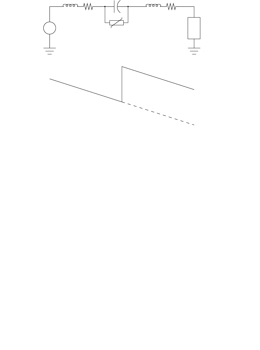
11.4.1.2 Series Capacitor
On distribution lines, much of the voltage drop is due to a circuit’s induc-
tance. If we add a capacitor in series with the inductance, the capacitor
cancels out a portion of the inductance (see Figure 11.24). Now, the circuit
has less total inductance, so fluctuations in load cause less voltage drop. A
series capacitor is a passive circuit element. It responds instantaneously and
automatically. Series capacitors help with voltage regulation as well as
improving voltage flicker.
The best place for a series capacitor depends on where the complaining
customers are relative to the offending load. Customers upstream of the
series capacitor see no difference in flicker. Voltage improves downstream
of the series capacitor. Sizing and placement involves tradeoffs. Ideally, we
want to size the capacitor such that its impedance equals the circuit imped-
ance to the fluctuating load (smaller series capacitor impedances are more
expensive: more kvars, more units in parallel). For placement, a good rule
of thumb is electrically half way between the source and the fluctuating load
— the point where the voltage drop is half of the total voltage drop due to
the fluctuating load. Locations closer to the source reduce flicker for more
customers but increase fault duties. An IEEE working group suggests a rule-
of-thumb location where the voltage drop is one-third to one-half of the total
drop (Miske, 2001).
FIGURE 11.24
Series capacitor.
Fluctuating
load
Overvoltage
protection
Source
Voltage drop along
the circuit due to the
fluctuating load
With
capacitor
Without
capacitor
Z
1
Z
2
C
1791_book.fm Page 575 Monday, August 4, 2003 3:20 PM
(C) 2004 by CRC Press LLC

576 Electric Power Distribution Handbook
Series capacitors can superbly compensate flicker from fluctuating induc-
tive loads. For resistive loads, series capacitors provide much less benefit.
The voltage drop through the distribution system is approximately I
R
R +
I
X
X. Reducing X with a series capacitor helps reduce the I
X
X term for fluc-
tuating I
X
; but if just I
R
fluctuates, series capacitors provide little benefit.
Electrically, series capacitors elegantly solve voltage flicker; in practice,
they are not widely used, mainly because of
• Reliability of short-circuit protection — Historically, spark gaps were
used to protect the capacitors during downstream faults. Utilities
have had many problems with failures.
• Cost — Series capacitors are nonstandard and must be custom engi-
neered.
• Unusual — Line crews and field engineers find series capacitors
strange. For example, if crews switch in a shunt capacitor down-
stream of a series capacitor, the voltage may go down instead of up.
Increased fault currents downstream of the capacitor can make coor-
dination of protective devices more difficult.
• Ferroresonance — Series capacitors may also ferroresonate with
downstream transformers under the right conditions.
A key design issue is the voltage across the capacitor during faults down-
stream of the unit. During a fault downstream of the series capacitor, the
voltage across the capacitor units is the short-circuit current times the capac-
itor impedance. Depending on the impedances upstream of the capacitor
relative to the capacitor size, the voltage across the series capacitor can
exceed the system’s nominal voltage. When calculating the available fault
current downstream of the capacitor, include the impedance reduction
caused by the capacitor. The fault current normally can rise past the capacitor
(depending on the amount of capacitance relative to the system impedance
and the line X/R ratio). The highest fault current can be some distance from
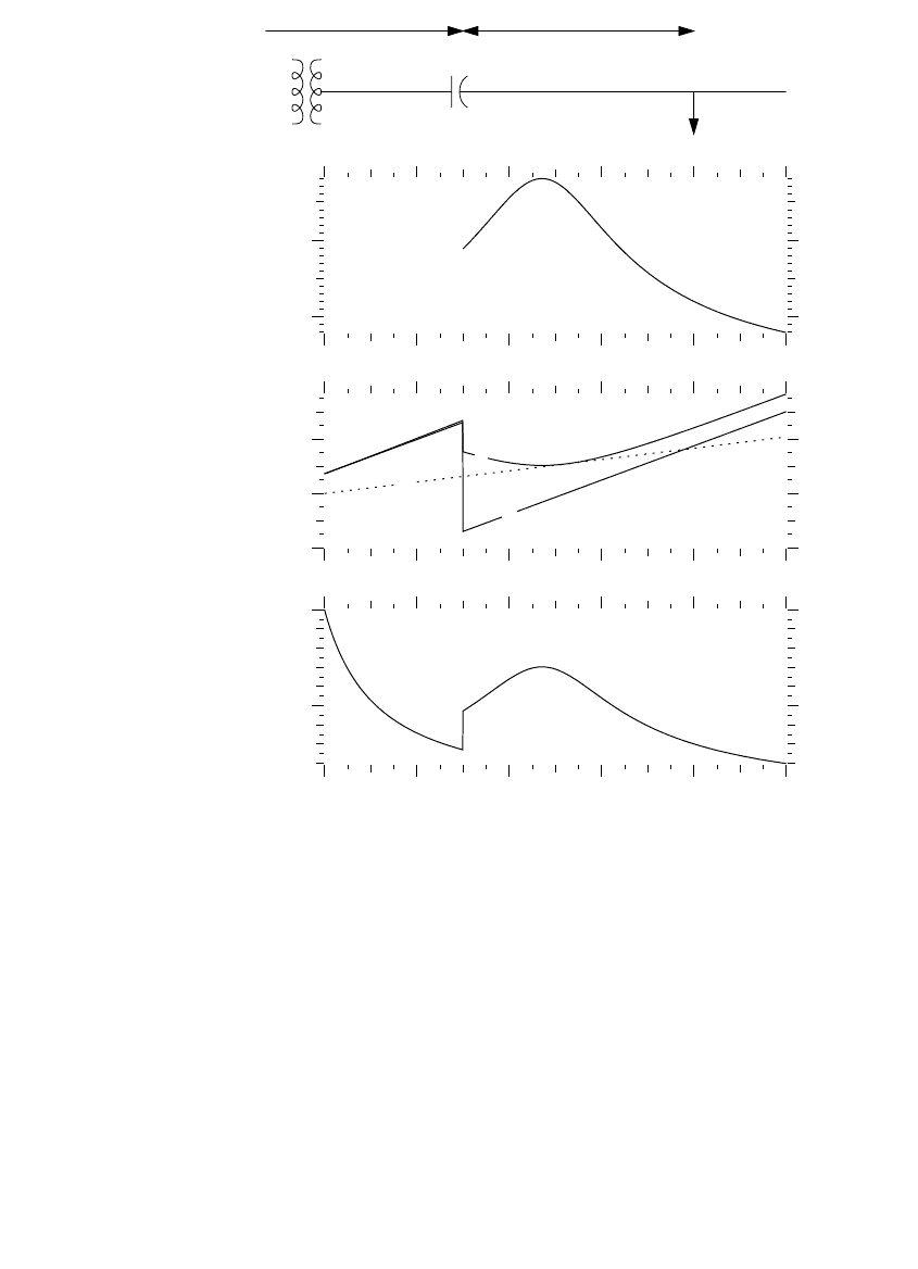
the capacitor. Figure 11.25 shows an example on a 12.5-kV system for a series
capacitor placed 3 mi from the substation to compensate for a fluctuating
load at 8 mi from the substation. The series capacitor significantly alters the
fault-current profile, and the fault current impresses significant voltage
across the capacitor. Some sort of protection is needed to prevent this.
The increased fault current raises the primary voltage and the customers’
voltage during the fault. Figure 11.26 shows a profile of the line voltages for
a fault at 4.75 mi for the example shown in Figure 11.25. Under this scenario,
the fault current is leading (capacitive), so voltages rise along the line until
the series capacitor. These overvoltages are unacceptable, so some overvolt-
age protection across the capacitor is vital to prevent them. This example
has a rather poor choice of location and impedances, but it illustrates how
important it is to consider these applications carefully. Reducing the imped-
ance of the capacitor reduces the overvoltages and reduces the fault currents.
1791_book.fm Page 576 Monday, August 4, 2003 3:20 PM
(C) 2004 by CRC Press LLC
Other Power Quality Issues 577
Lowering the capacitor’s impedance to maintain a total line impedance that
is always reactive (never capacitive) eliminates the problem of overvoltages.
But we still have higher fault currents downstream of the capacitor, and
lowering the capacitor’s impedance reduces the flicker-prevention capability.
Several protection arrangements have been used to protect capacitors from
overvoltages. A spark gap is the simplest device but has been problematic.
Duke Power reported that many of the gaps on their units kept arcing and
started fires (Morgan et al., 1993). Gap erosion also reduced protection and
FIGURE 11.25
Fault-current profile on a 12.5-kV circuit with a series capacitor located 3 miles from the
substation (the same line parameters as Figure 7.11, 500-kcmil AAC conductors). The series
capacitor has no short-circuit protection.
0
24
6810
5
10
R
X
Z
0
24
6810
-2
0
2
0
24
6810
10
20
Distance from the substation, miles
X
C
= 4W
X
L1
= 2.6W X
L2
= 3.1W
Vo ltage across the
capacitor for a
fault at the given
location, kV
Impedances to the
fault, W
Three-phase fault
current, kA
1791_book.fm Page 577 Monday, August 4, 2003 3:20 PM
(C) 2004 by CRC Press LLC