Shcneider Electric. Reference manual. PL7 Micro/Junior/Pro. Description of the PL7 software
Подождите немного. Документ загружается.

PL7 object language
35015365.01 07/2008 51
Description of
Indexable
Objects
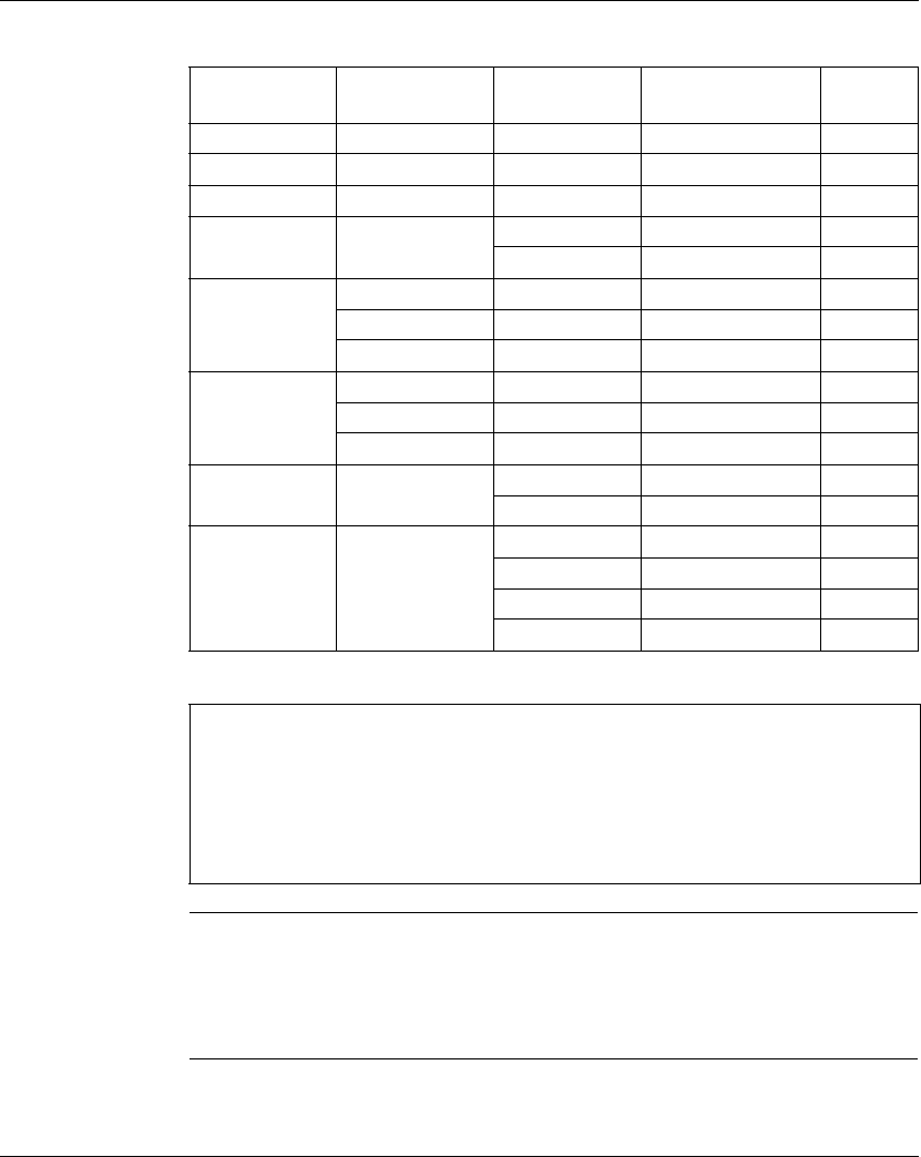
The following table defines the objects that can be indexed.
Indexing Double
Words
The real address = direct address of the indexed double word + twice the content of
the index word.
Example: %MD6[%MW100]
If %MW100=10, the word addressed will be 6 + 2 x 10 -->%MD26.
Type Format Address Example Write
access
Input bits Boolean %Ixy.i[index] %I21.3[%MW5] No
Output bit Boolean %Qxy.i[index] %Q32.4[%MW5] Yes
Internal bit Boolean %Mi[index] %M10[%MW5] Yes
Grafcet bit Boolean %Xi[index] %X20[%MW5] No
%Xj.i[index] %X2.3[%MW5] No
Internal words Single length %MWi[index] %MW30[%MW5] Yes
Double length %MDi[index] %MD15[%MW5] Yes
Floating point %MFi[index] %MF15[%MW5] Yes
Constant word Single length %KWi[index] %KW50[%MW5] No
Double length %KDi[index] %KD50[%MW5] No
Floating point %KFi[index] %KF50[%MW5] No
Grafcet words Single length %Xi .T[index] %X20 .T[%MW5] No
%Xj.i .T[index] %X2.3 .T[%MW5] No
Word table %MWi[index]:L %MW50[%MW5]:10 Yes
%MDi[index]:L %MD40[%MW5]:10 Yes
%KWi[index]:L %KW70[%MW5]:20 No
%KDi[index]:L %KD80[%MW5]:10 No
Note: the maximum values of the indexes depend on the types of object indexed.
z For discrete input/output bits: 0<i+index<m (m being the maximum number
of module inputs/outputs).
z For all other objects (except double length or floating objects):
0<i+index<Nmax, Nmax = maximum size depends on the size defined in the
configuration.
For double length or floating words: 0<i+index<Nmax-1.

PL7 object language
52
35015365.01 07/2008
Index Overflow The index will overflow as soon as the address of an indexed object exceeds the
limits of the field containing the same type of object, i.e. when:
z object address + index content less than zero,
z object address + index content greater than the maximum limit configured.
If the index overflows, the system resets the system bit %S20 to 1 and the object is
assigned with an index value of 0.
The following table gives the conditions for setting the system bit %S20 to 1 and 0.
Set to 1 Reset to 0
z set to 1 by the system on index overflow z set to 0 by the user after modifying the
index

PL7 object language
35015365.01 07/2008 53
Grafcet objects
Bit objects The following table summarizes all the Grafcet bit objects available and describes
their role.
These bits are set to 1 when the step or the macro step is active, to 0 when it is
inactive.
Word objects The following table summarizes all the Grafcet word objects available and describes
their role.
These words are incremented every 100 ms and take a value of between 0 and
9999.
Type Description
%Xi status of step i of the main graph (Chart).
%XMj status of the Grafcet macro step j.
%Xj.i status of the i step of the Grafcet j macro step
%Xj.IN status of the input step of the macro step
%Xj.OUT status of the output step of the macro step
Type Description
%Xi.Ti activity time for Grafcet step i.
%Xj.i.T activity time for the i step of the Grafcet j macro step
%Xj.IN.T activity time for step i of macro step j which allows it to find out about the status
of step i of the Grafcet macro step j.
%Xj.OUT.T activity time for the input step of the macro step
%Xj.OUT activity time for the output step of the macro step

PL7 object language
54
35015365.01 07/2008
Symbolizing
Role Symbols are used to address PL7 language objects by name or customized
mnemonics.
Syntax A symbol is a string of a maximum of 32 alphanumeric characters the first character
of which is alphabetic.
A symbol begins with a capital letter, the others are in lower case (e.g.: Burner_1).
When it is being entered the symbol can be written in capitals or lower case
(e.g.: BURNER_1), the program automatically puts the symbol in the correct form.
Characters that
can be used
The following table provides the characters that can be used when creating symbols.
A certain number of words are reserved by the language and cannot be used as
symbols, see (See Reference Manual, Volume 3).
Editing symbols Symbols are defined and associated with language objects by the variables editor.
A comment of 508 characters can be associated with each symbol.
Symbols and their comments are stored on the terminal hard disk and not in the PL7.
Type Description
alphabetic
capitals
"A - Z" and the following letters
"ÀÁÂÃÄÅÆÇÈÉÊËÌÍÎÏDÑÒÓÓÕÖØÙÚÛÜYp"
alphabetic lower
case
"a - z" and the accented letters àáâãäåæçèéêëìíîïñòóôõöØùúûüypßÿ
numerical figures from 0 - 9 (they cannot be in first place of the symbol).
the character "_" it cannot be either at the beginning of the symbol nor at the end.
PL7 object language
35015365.01 07/2008 55
Objects which
can be made into
symbols
All PL7 objects can be symbolized except for table type structured objects and
indexed objects, but if the base object or index is symbolized the symbol is used in
the structured object.
Examples:
z if the word %MW0 has "Temperature" for a symbol, the word table %MW0:12 is
symbolized by Temperature:12,
z the word %MW10 hasOven_1 for a symbol, the indexed word %MW0[%MW10]
is symbolized by Temperature[Oven_1].
Object bits extracted from words, bits or function block words can be symbolized but
if they are not symbolized they can inherit the symbol from the base object.
Examples:
z if the word %MW0 has Pump_state for a symbol and if the bit extracted from
the word %MW0:X1 is not symbolized, it inherits the symbol from the word,
%MW0:X1 has as its symbol: Pump_ state:X1,
z if the function block %TM0 has for its symbol Time_oven1 and if the output
%TM0.D is not symbolized, it inherits the block symbol, %TM0.D has as its
symbol: Time_oven.D.
Object which are
only symbolic
DFB function block parameters can only be accessed in the form of symbols. These
objects are defined by the following syntax:
Name_DFB.Name_parameter
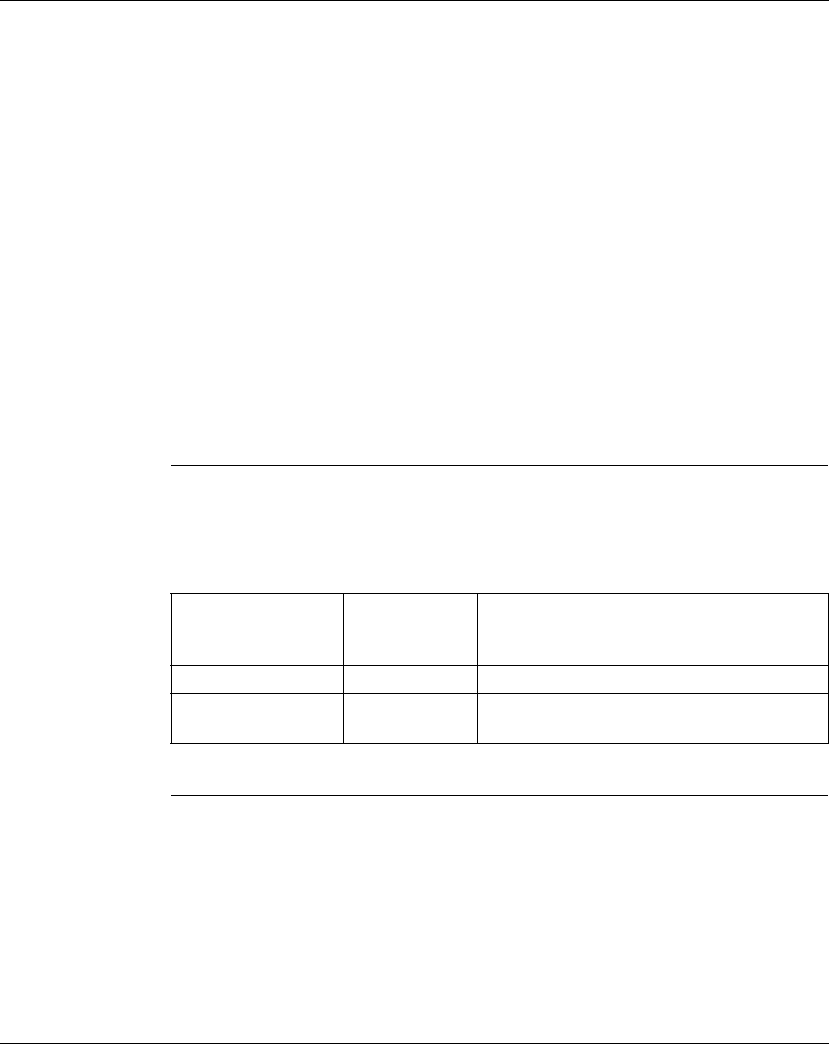
The elements have the following meaning and characteristics.
Example: Gap.check for the gap output of the DFB instance named Check.
Element Maximum
number of
charactes
Description
Name_DFB 32 name given to the DFB function block used.
Name_parameter 8 name given to the output parameter or public
variable.
PL7 object language
56
35015365.01 07/2008
Presymbolized objects
Role Certain application specific functions (example: counting, axes request, …) support
an automatic symbolization of the objects which are linked to them.
If you give the generic symbol of the module’s %CHxy.i channel, all of the symbols
of the objects linked to this channel can then be automatically generated on request.
Syntax These objects are symbolized with the following syntax:
PREFIX_USER_SUFFIX_MANUFACTURER
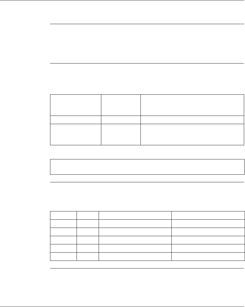
The elements have the following meaning and characteristics:
Example This example shows a counting module situated in slot 3 of the automatic tray.
If the generic symbol (prefix-user) given to channel 0 is Pieces_count, the
following symbols are automatically generated.
Element Maximum
number of
characters
Description
PREFIX_USER 12 generic symbol given to the channel by the user
SUFFIX_MANUFACT
URER
20 part of the symbol which corresponds to the bit
object or word of the channel given by the
system
Note: as well as the symbol, a manufacturer’s comment is automatically
generated, this comment recalls succinctly the object’s role.
Address Type Symbol Comment
%CH3.0 CH
%ID3.0 DWORD Pieces_count_cur-meas Counter current value
%ID3.0.4 DWORD Pieces_count_capt Counter captured value
%I3.0 EBOOL Pieces_count_enab_activ Counter enable active
%I3.0.1 EBOOL Pieces_count_pres_done Preset done
35015365.01 07/2008 57
3
User memory
Presentation
Aim of this
Chapter
This chapter describes the memory structure of Micro and Premium PL7s.
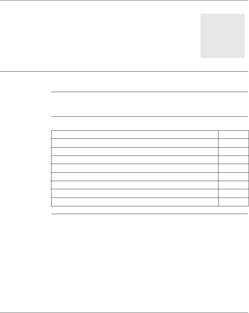
What's in this
Chapter?
This chapter contains the following topics:
Topic Page
Memory structure of Micro PLCs 58
Memory structure for Premium PL7s 60
Description of bits memory 62
Word memory outline 64
Characteristics of TSX 37 PL7 memory 65
Memory characteristics of TSX/PCX 57 10/15/20/25/26/28 PLCs 67
Characteristics of TSX/PCX 57 30/35/36 PL7 memories 70
Characteristics of TSX 57 453/4823 PL7 memory 72
User memory
58
35015365.01 07/2008
Memory structure of Micro PLCs
General The memory space of Micro PLCs that is user-accessible can be broken down into
two distinct sub-sets:
z bit memory
z word memory
Bit memory The bit memory is located in the processor's built-in RAM. It contains an image of
the 1280 bit objects.
Role of word
memory
The word memory (16 bits) supports:
z data: dynamic application data and system data,
z the program: descriptors and executable code of tasks,
z constants: constant words, initial values and input/output configuration.
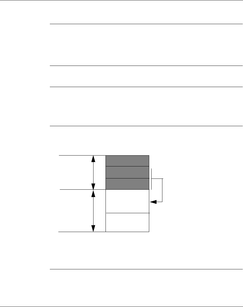
Structure
without memory
extension card
The data, program and constants are supported by the processor's internal RAM.
The following diagram shows the memory structure.
The processor's built-in Flash EPROM memory can be used to back up:
z the application program (9 or 15 KWords depending on the processor),
z 1000 %MWi internal words.
Data
Program
Constants
Backup of
program and
constants
%MW
backup
Internal
RAM
Internal
Flash
EPROM
User memory
35015365.01 07/2008 59
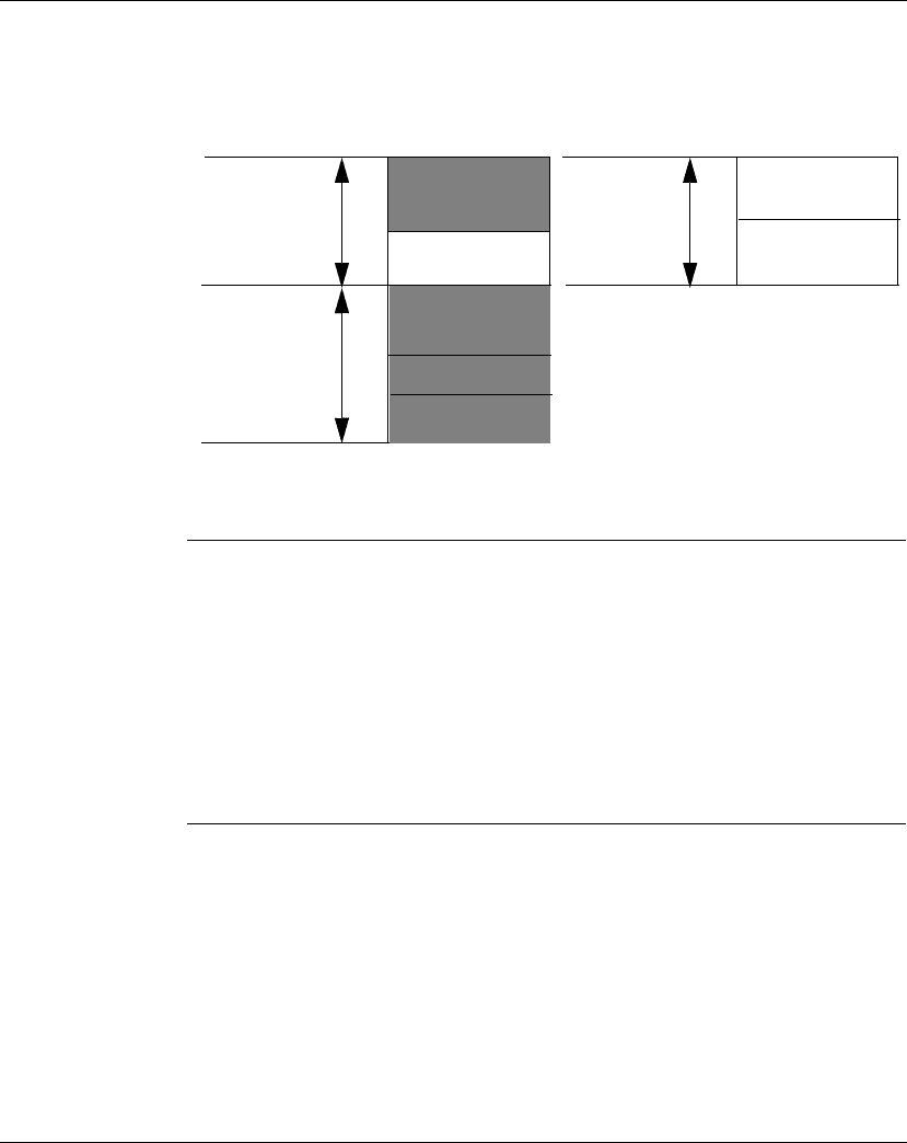
Structure with
memory
extension card
The data are supported by the processor's internal RAM.
The program and constants are supported by the memory extension card.
The following diagram shows the memory structure.
The 10/16 KWords of Flash EPROM memory (depending on the processor) built into
the processor can be used to back up 1000 %MWi internal words.
Memory backup The RAM can be backed up using a Ni-Cad battery:
z supported by the processor for the bit memory and internal RAM,
z inserted into the card for a RAM memory card.
In order to copy the application to the internal FLASH EPROM memory, the PLC
must not have a PCMCIA card fitted and the application must be of less than or
equal to 9/15 KWords in size (depending on the processor).
The application is automatically transferred from the internal FLASH EPROM to
RAM when the application is lost from RAM (failed backup or no battery).
A manual transfer can also be requested from a programming terminal.
Data
Program
Constants
Internal
RAM
External RAM or
Flash EPROM
memory card
Zone
cannot be used
%MW
backup
Internal
Flash
EPROM
User memory
60
35015365.01 07/2008
Memory structure for Premium PL7s
General Premium PL7 memory space comprises only one set.
The bit memory is integrated into the word memory (in the data field). It is limited to
4096 bits.
Role of the words
memory
The words memory (16 bits) supports:
z data: dynamic application data and system data (the system reserves a RAM
memory field of at least 5 K words)
z the program: descriptors and executable code for tasks,
z constants: constant words, initial values and input/output configuration.
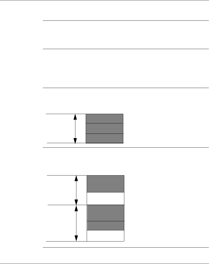
Structure
without
extension
memory card
Program, data and constants are supported by the internal RAM memory in the
processor module.
The following diagram describes the memory structure.
Structure with
extension
memory card
Data is supported by the processor module internal RAM memory.
Programs and constants are supported by the extension memory card.
The following diagram describes the memory structure.
Data
Program
Constants
internal
RAM
Data
Program
Constants
internal
RAM
RAM
memory
card or
external
EPROM
Flash