Рави Додданнавар, Андрис Барнард. Practical Hydraulic Systems
Подождите немного. Документ загружается.

128
Practical Hydraulic Systems
2.
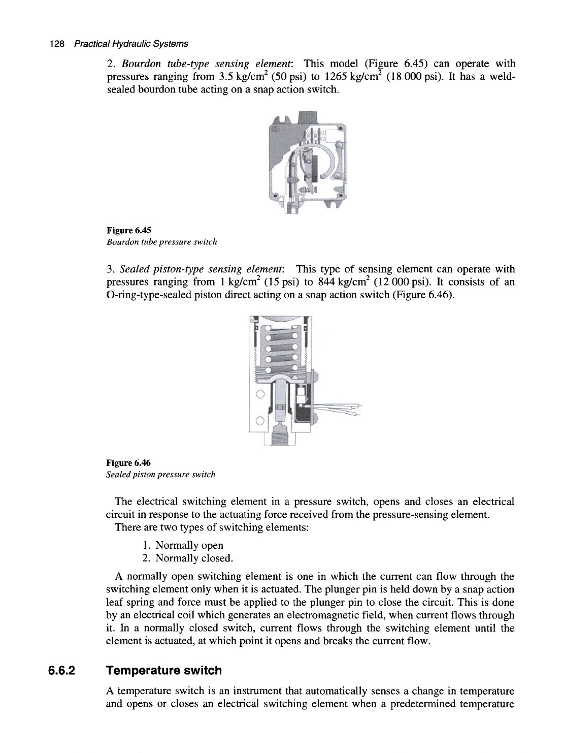
Bourdon tube-type sensing element: This model (Figure 6.45) can operate with
pressures ranging from 3.5 kg/cm^ (50psi) to 1265 kg/cm^ (18 000 psi). It has a weld-
sealed bourdon tube acting on a snap action switch.
Figure 6.45
Bourdon tube pressure switch
3.
Sealed piston-type sensing element: This type of sensing element can operate with
pressures ranging from
1
kg/cm^ (15 psi) to 844kg/cm^ (12 000 psi). It consists of an
O-ring-type-sealed piston direct acting on a snap action switch (Figure 6.46).
Figure 6.46
Sealed piston pressure switch
The electrical switching element in a pressure switch, opens and closes an electrical
circuit in response to the actuating force received from the pressure-sensing element.
There are two types of switching elements:
1.
Normally open
2.
Normally closed.
A normally open switching element is one in which the current can flow through the
switching element only when it is actuated. The plunger pin is held down by a snap action
leaf spring and force must be applied to the plunger pin to close the circuit. This is done
by an electrical coil which generates an electromagnetic field, when current flows through
it. In a normally closed switch, current flows through the switching element until the
element is actuated, at which point it opens and breaks the current flow.
6.6.2 Temperature switch
A temperature switch is an instrument that automatically senses a change in temperature
and opens or closes an electrical switching element when a predetermined temperature
Control components
in a
hydraulic system
129
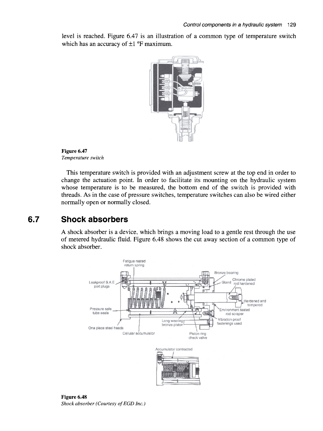
level is reached. Figure 6.47 is an illustration of a common type of temperature switch
which has an accuracy of
±1
T maximum.
Figure 6.47
Temperature switch
This temperature switch is provided with an adjustment screw at the top end in order to
change the actuation point. In order to facilitate its mounting on the hydraulic system
whose temperature is to be measured, the bottom end of the switch is provided with
threads. As in the case of pressure switches, temperature switches can also be wired either
normally open or normally closed.
6.7 Shock absorbers
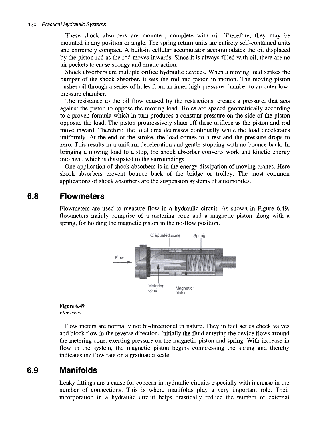
A shock absorber is a device, which brings a moving load to a gentle rest through the use
of metered hydraulic fluid. Figure 6.48 shows the cut away section of a common type of
shock absorber.
Fatigue rested
return spring
Leakproof S.A.E
port plugs
Pressure safe
_
tube seals
One piece steel heads
Bronze bearing
Chrome plated
Gland rod hardened
Cellular accumulator
Accumulator contracted
Figure 6.48
Shock absorber (Courtesy ofEGD Inc.)
130
Practical Hydraulic Systems
These shock absorbers are mounted, complete with oil. Therefore, they may be
mounted in any position or angle. The spring return units are entirely self-contained units
and extremely compact. A built-in cellular accumulator accommodates the oil displaced
by the piston rod as the rod moves inwards. Since it is always filled with oil, there are no
air pockets to cause spongy and erratic action.
Shock absorbers are multiple orifice hydraulic devices. When a moving load strikes the
bumper of the shock absorber, it sets the rod and piston in motion. The moving piston
pushes oil through a series of holes from an inner high-pressure chamber to an outer low-
pressure chamber.
The resistance to the oil flow caused by the restrictions, creates a pressure, that acts
against the piston to oppose the moving load. Holes are spaced geometrically according
to a proven formula which in turn produces a constant pressure on the side of the piston
opposite the load. The piston progressively shuts off these orifices as the piston and rod
move inward. Therefore, the total area decreases continually while the load decelerates
uniformly. At the end of the stroke, the load comes to a rest and the pressure drops to
zero.
This results in a uniform deceleration and gentle stopping with no bounce back. In
bringing a moving load to a stop, the shock absorber converts work and kinetic energy
into heat, which is dissipated to the surroundings.
One application of shock absorbers is in the energy dissipation of moving cranes. Here
shock absorbers prevent bounce back of the bridge or trolley. The most common
applications of shock absorbers are the suspension systems of automobiles.
6.8 Flowmeters
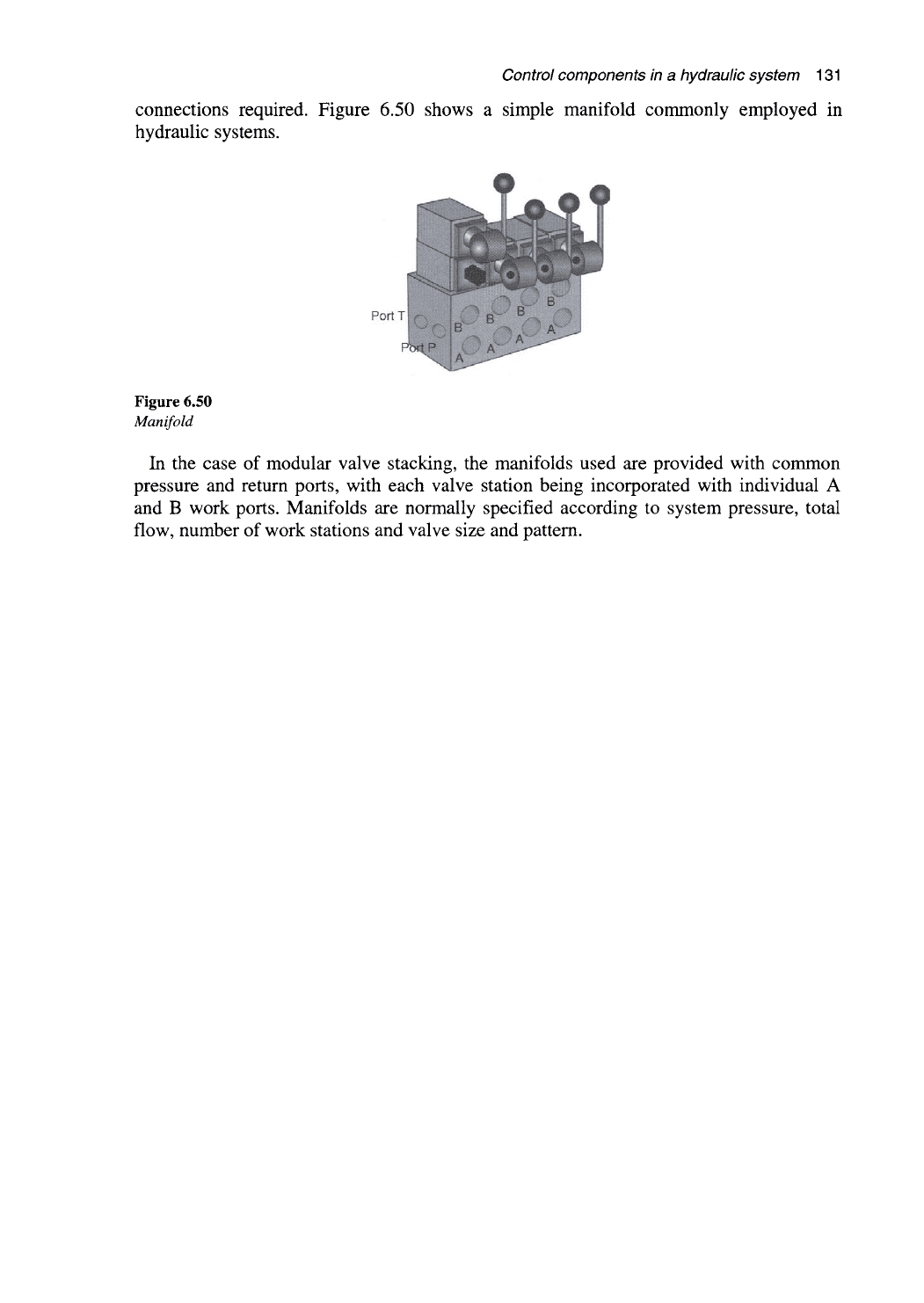
Flowmeters are used to measure flow in a hydraulic circuit. As shown in Figure 6.49,
flowmeters mainly comprise of a metering cone and a magnetic piston along with a
spring, for holding the magnetic piston in the no-flow position.
Graduated scale Spring
Magnetic
piston
Figure 6.49
Flowmeter
Flow meters are normally not bi-directional in nature. They in fact act as check valves
and block flow in the reverse direction. Initially the fluid entering the device flows around
the metering cone, exerting pressure on the magnetic piston and spring. With increase in
flow in the system, the magnetic piston begins compressing the spring and thereby
indicates the flow rate on a graduated scale.
6.9 Manifolds
Leaky fittings are a cause for concern in hydraulic circuits especially with increase in the
number of connections. This is where manifolds play a very important role. Their
incorporation in a hydraulic circuit helps drastically reduce the number of external
Control components in
a
hydraulic system
131
connections required. Figure 6.50 shows a simple manifold commonly employed in
hydraulic systems.
PortT
Figure 6.50
Manifold
In the case of modular valve stacking, the manifolds used are provided with common
pressure and return ports, with each valve station being incorporated with individual A
and B work ports. Manifolds are normally specified according to system pressure, total
flow, number of work stations and valve size and pattern.
Hydraulic accessories
7.1 Objectives
After reading this chapter, one will be able to:
• Know the various accessories used in a hydraulic system
• Understand the function and construction of a reservoir
• Understand various types of accumulators from their design and construction
point of view
• Select and specify accumulators for various applications
• Understand the concept of heat exchangers and their functions
• Know the specifications and construction of pipes and hoses
• Select and size hoses and pipes for different hydraulics applications.
7.2 Introduction
When we talk about hydraulics, it is not only fluids that come into one's mind. Also a
discussion on hydraulics is not complete with only a discussion on pumps, motors and valves.
There are other important components and aggregates in a hydraulic system listed under the
category of hydraulic accessories. These accessories provide a clean and uninterrupted supply
of fluid to a hydraulic system. In this chapter let us concentrate on learning how these
accessories contribute not only to an efficient but also effective hydraulic system.
7.3 TJie reservoir system
The 'reservoir' as the name suggests, is a tank which provides uninterrupted supply of
fluid to the system, by storing the required quantity of fluid. The hydraulic fluid is
considered the most important component in a hydraulic system or in other words its very
heart. Since the reservoir holds the hydraulic fluid, its design is considered quite critical.
The reservoir in addition to storing the hydraulic fluid, performs various other important
functions such as dissipating heat through its walls, conditioning of the fluid by helping
settle the contaminants, aiding in the escape of air and providing mounting support for the
pump and various other components. These are discussed in detail below. Some of the
essential features of any good reservoir include components such as:
• Baffle plate for preventing the return fluid from entering the pump inlet
• Inspection cover for maintenance access
Hydraulic accessories 133
• Filter breather for air exchange
• Protected filler opening
• Level indicator for monitoring the fluid level
• Connections for suction, discharge and drain lines.
The proper design of a suitable reservoir for a hydraulic system is essential to the
overall performance and life of the individual components. It also becomes the principle
location where the fluid can be conditioned in order to enhance its suitability. Sludge,
water and foreign matter such as metal chips have a tendency to settle in the stored fluid
while the entrained air picked up by the oil is allowed to escape in the reservoir. This
makes the construction and design of hydraulic reservoirs all the more crucial.
Many factors are taken into consideration when selecting the size and configuration of a
hydraulic reservoir. The volume of the fluid in a tank varies according to the temperature
and state of the actuators in the system. The volume of fluid in the reservoir is at a
minimum with all cylinders extended and a maximum at high temperatures with all
cylinders retracted. Normally a reservoir is designed to hold about three to four times the
volume of the fluid taken by the system every minute. A substantial space above the fluid
in the reservoir must be included to allow volume change, venting of any entrapped air
and to prevent any froth on the surface from spilling out.
A properly designed reservoir can also help in dissipating the heat from the fluid. In
order to obtain maximum cooling, the fluid is forced to follow the walls of the tank from
the return line. This is normally accomplished by providing a baffle plate in the
centerline.
The level of fluid in a reservoir is critical. If the level is too low, there is a possibility of
air getting entrapped in the reservoir outlet pipeline going to the pump suction. This may
lead to cavitation of the pump resulting in pump damage.
The monitoring of the temperature of the fluid in the reservoir is also important. At the
very least, a simple visual thermometer whose ideal temperature range is around 45 °C
(113
^^F)
to 50 °C (122 °F), needs to be provided on the reservoir.
There are basically two types of reservoirs:
1.
Non-pressurized reservoir
2.
Pressurized reservoir.
7.3.1 Non-pressurized reservoir
As the name suggests this type of reservoir is not pressurized, which means, the pressure
in the reservoir will at no point of time rise above that of atmospheric pressure. Very
extensively used in hydraulic systems, these reservoirs are provided with a vent to ensure
that the pressure within, does not rise above the atmospheric value.
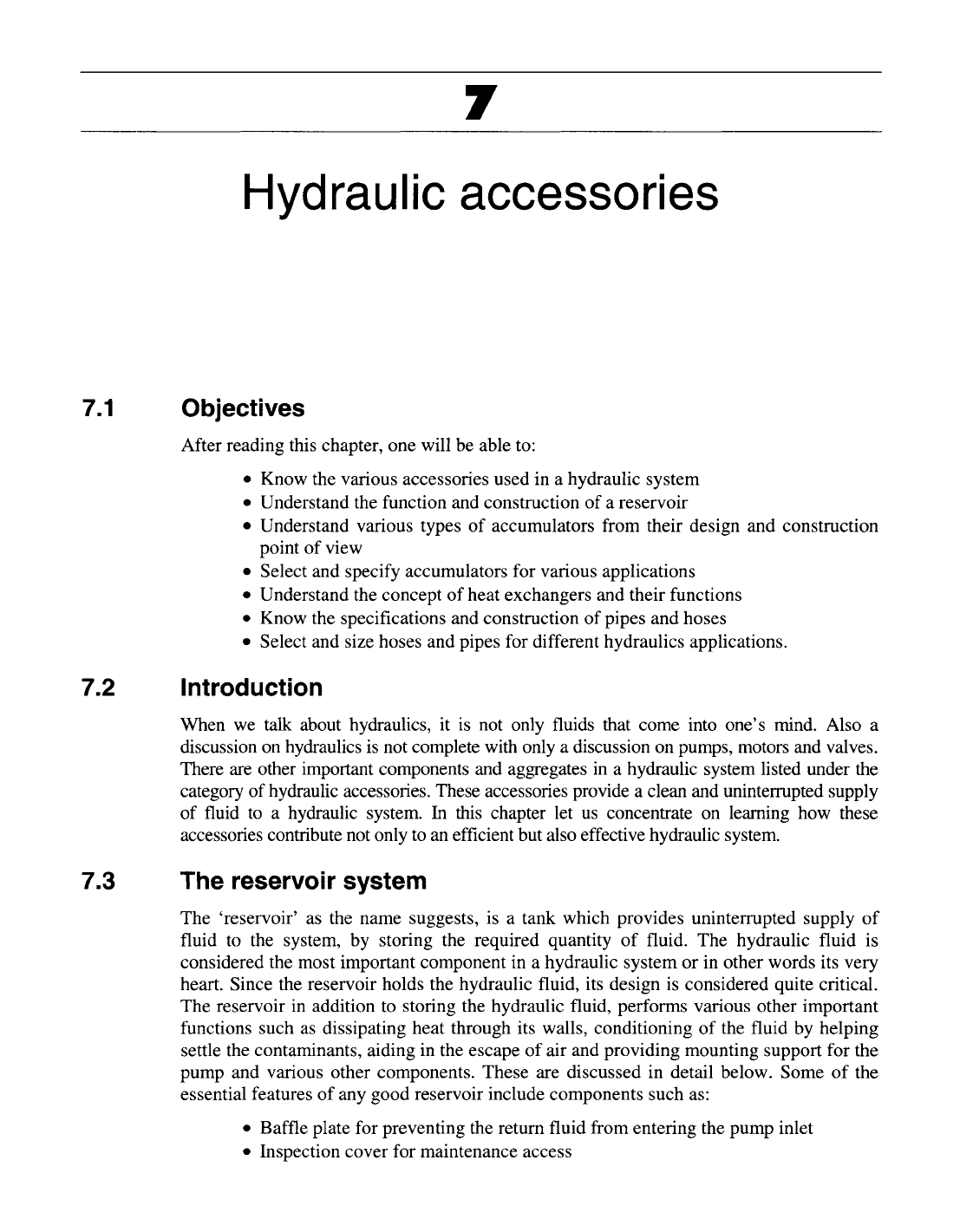
Figure 7.1 shows the typical construction of such a reservoir conforming to industry
standards.
These reservoirs are constructed with welded steel plates. The inside surfaces are painted
with a sealer, to prevent the formation of rust which might in turn occur due to the presence
of condensed moisture. The bottom plate is sloping and contains a drain plug at its lowest
point, to allow complete draining of the tank when required. In order to access all the
internals for maintenance, removable covers are provided. A level indicator which is an
important part of the reservoir, is also incorporated. This allows one to see the actual level
of the fluid in the reservoir, while the system is in operation. A vented breather cap with an
air filter screen helps in venting the entrapped air easily. The breather cap allows the tank to
breathe when the fluid level undergoes changes in tune with the system demand.
134
Practical Hydraulic Systems
Drain return
Mounting plate
for electric motor
and pump
Return line
Slight glass
Clean-out
Plate-both ends
Strainer
Drain
plug
Baffle
plate
Figure 7.1
Non-pressurized reservoir
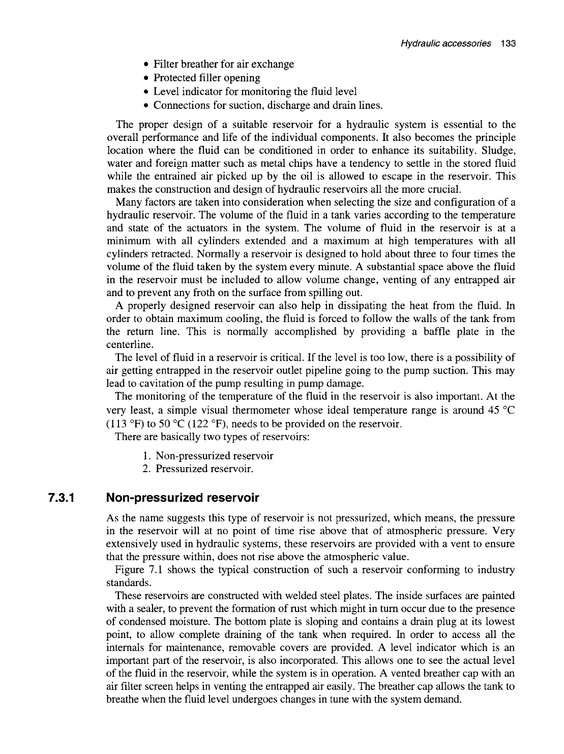
The baffle plate
in the
reservoir extends lengthwise across
the
center
of the
tank.
Figure 7.2 shows
a
cross-sectional view
of the
reservoir depicting
the
baffle plate
function.
2.
Turbulence
is
avoided
by
forcing fluid to take an indirect
path to the pump inlet
To pump
Return line
3. Oil
is
cooled and
air
seperated out when
it
reaches inlet
Baffle plate
1.
Return flow
is
directed
outward
to
tank wall
Figure 7.2
Baffle plate controls direction of flow in a non-pressurized reservoir
The height
of the
baffle plate
in the
reservoir
is
about
70% of the
maximum fluid
height. The purpose
of
the baffle plate
is to
separate
the
pump inlet line from
the
return
Hydraulic accessories 135
line.
This is done to prevent the same fluid from circulating continuously within the tank.
In this way it is ensured that all the fluid is uniformly used by the system.
Essentially the baffle plate performs the following functions:
• It permits foreign substances to settle at the bottom
• It allows entrained air to escape from the fluid
• It prevents localized turbulence in the reservoir
• It promotes heat dissipation from the reservoir walls.
The reservoir is designed and constructed to facilitate the installation of a pump and
motor on its top surface. A smooth machined surface of adequate strength is provided to
support and maintain the alignment of the two units.
The return line enters the reservoir from the side of the baffle plate, which is opposite to
the pump suction line. It should be below the fluid surface level all the time, in order to
prevent foaming of the fluid. Similarly, the strainer or the foot valve should be located
well below the normal fluid level in the reservoir and at least 1 in. or 2.5 cms above the
bottom of the reservoir. If the strainer is located too high, it will lead to the formation of a
vortex or crater that will permit ingress of air into the pump suction line.
The sizing of the reservoir is based on the following criteria:
• It should have sufficient volume and space to allow the dirt and metal chips to
settle and the air to escape freely.
• It should be capable of holding all the fluid that might be drained from the system.
• It should be able to maintain the fluid level high enough to prevent air escaping
into the pump suction line.
• The surface area of the reservoir should be large enough to dissipate the heat
generated by the system.
• It should have sufficient free board over the fluid surface to allow thermal
expansion of the fluid.
For most hydraulic systems, a reservoir having a capacity of three times the volumetric
flow rate of the pump has been found to be adequate.
7.3.2 Pressurized reservoirs
Although it has been observed that non-pressurized reservoirs are the most suitable ones
in a hydraulic system, certain hydraulic systems need to have pressurized reservoirs due
to the nature of their application. For example, the Navy's aircraft and missile hydraulic
systems essentially need pressurized reservoirs in order to provide a positive flow of fluid
at higher altitudes where lower temperatures and pressure conditions are encountered.
Air-pressurized reservoir
The required pressure in the reservoir is maintained by means of compressed air.
Compressed air is generally introduced into the reservoir from the top at a pressure
specified by the manufacturer. In order to control this pressure, a pressure control device
such as a pressure regulator is provided in the airline entering the reservoir. The function
of this pressure regulator is to maintain a constant pressure in the reservoir, irrespective of
the level and temperature of fluid in the reservoir.
A pressurized reservoir will only have a single entry point for filling up the fluid in the
tank. Since the reservoir is always maintained at a pressure, it becomes important to have
a foolproof system with safety relief valves, for the filling of fluid in the reservoir.
Sufficient guidelines are provided by all manufacturers of such pressurized reservoirs.
136
Practical Hydraulic Systems
7.4 Filters and strainers
7.4.1 Introduction
A modem hydraulic system must be highly reliable and provide greater levels of accuracy
in its operation. The key to this is the requirement for high precision-machined
components. Cleanliness of the hydraulic fluid is a vital factor in the efficient operation of
the fluid power components. With the close tolerance design of pumps and valves,
hydraulic systems are being made to operate at increased pressure and efficiency levels.
The cleanhness of the fluid is an essential prerequisite for these components to perform as
designed and also for higher system reliability and reduced maintenance.
The worst enemy of these high-precision components is contamination of the fluid.
Essentially, contamination is the presence of any foreign material in the fluid, which
results in detrimental operation of any of the components in a hydraulic system. Fluid
contamination may be in the form of a liquid, gas or solid and can be caused by any of the
following:
Built into tlie system during component maintenance and assembly
The contaminants here include metal chips, bits of pipe threads, tubing burrs, pipe dope,
shreds of plastic tape, bits of seal material, welding beads, etc.
Generated within the system during operation
During the operation of a hydraulic system, many sources of contamination exist. They
include moisture due to water condensation in the reservoir, entrained gases, scale caused
by rust, bits of worn-out seal material, sludge and varnish due to oxidation of oil.
Introduced into the system from the external environment
The main source of contamination here is the use of dirty maintenance equipment such as
funnels, rags and tools. Washing of disassembled components in dirty oil can also
contaminate the fluid.
The foreign particles which are induced into the hydraulic system often get grounded
into thousands of fine particles. These minute particles tend to lodge into the space
between the control valve spools and their bores, causing the valve to stick. This
phenomenon is called silting.
In order to keep the fluid free from all these contaminants and also in order to prevent
phenomena such as silting, devices called filters and strainers are used in the hydraulic
system. In this section, let us study in detail on how these filters keep the system clean
and also dwelve on related topics such as micron rating, beta ratio and ISO code
cleanliness levels.
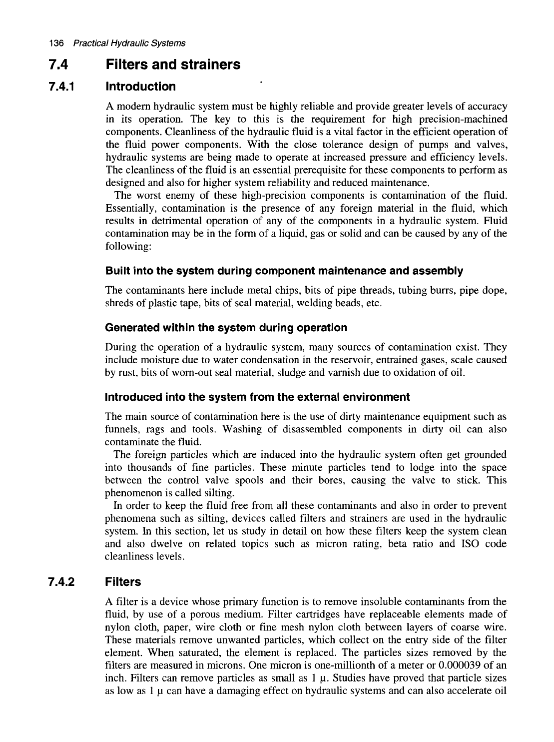
7.4.2 Filters
A filter is a device whose primary function is to remove insoluble contaminants from the
fluid, by use of a porous medium. Filter cartridges have replaceable elements made of
nylon cloth, paper, wire cloth or fine mesh nylon cloth between layers of coarse wire.
These materials remove unwanted particles, which collect on the entry side of the filter
element. When saturated, the element is replaced. The particles sizes removed by the
filters are measured in microns. One micron is one-millionth of a meter or 0.000039 of an
inch. Filters can remove particles as small as 1
|LI.
Studies have proved that particle sizes
as low as 1
|LI
can have a damaging effect on hydraulic systems and can also accelerate oil
Hydraulic accessories
137
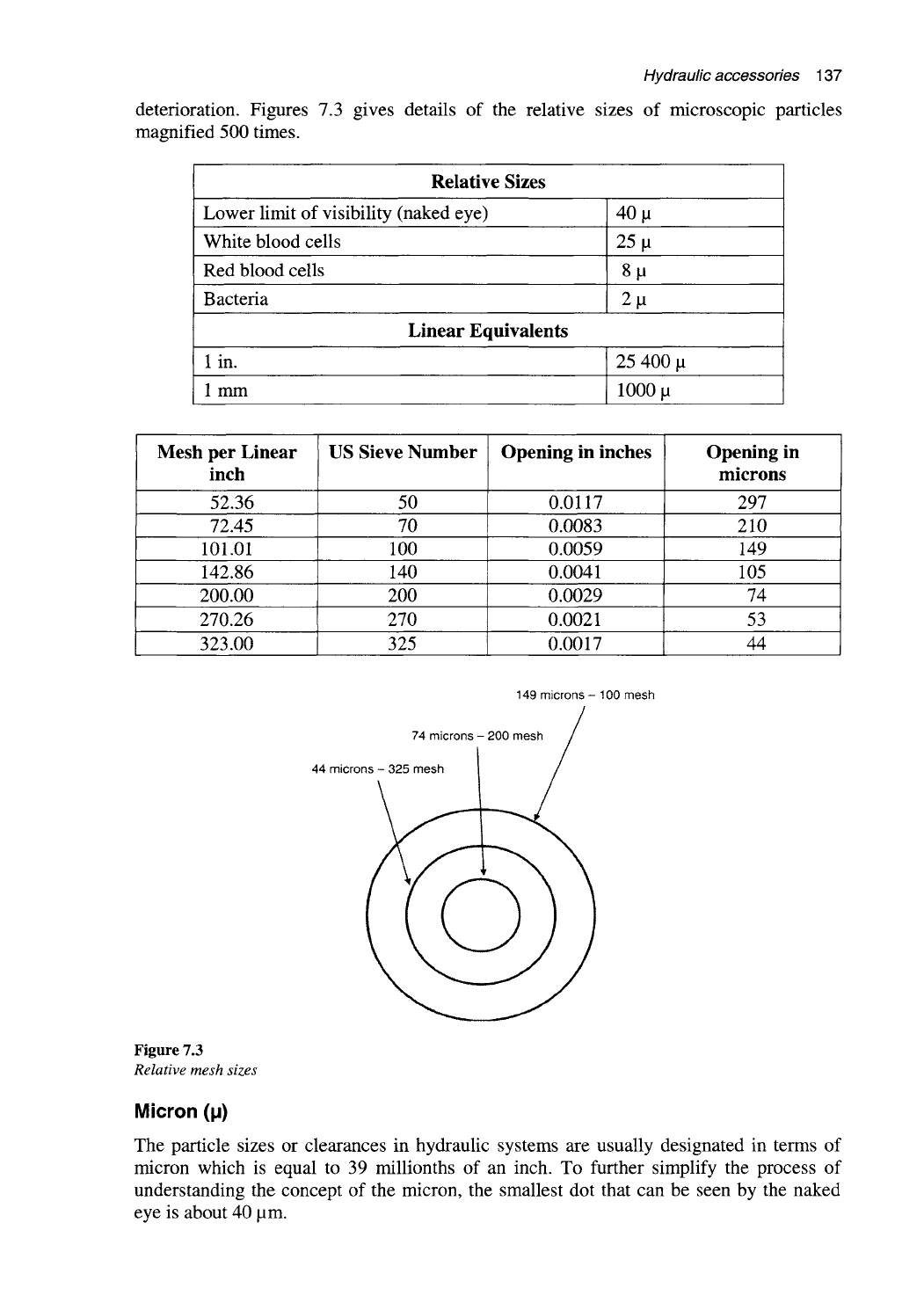
deterioration. Figures 7.3 gives details of the relative sizes of microscopic particles
magnified 500 times.
Relative Sizes
Lower limit of visibility (naked eye)
White blood cells
Red blood cells
Bacteria
40
M
25 |a
8M
2M
Linear Equivalents
lin.
1 mm
25 400
M
1000
M
Mesh per Linear
incli
52.36
72.45
101.01
142.86
200.00
270.26
323.00
US Sieve Number
50
70
100
140
200
270
325
Opening in inches
0.0117
0.0083
0.0059
0.0041
0.0029
0.0021
0.0017
Opening in
microns
297
210
149
105
74
53
44
149 microns - 100 mesh
74 microns - 200 mesh
44 microns - 325 mesh
Figure 7.3
Relative mesit sizes
Micron (p)
The particle sizes or clearances in hydraulic systems are usually designated in terms of
micron which is equal to 39 millionths of an inch. To further simplify the process of
understanding the concept of the micron, the smallest dot that can be seen by the naked
eye is about 40 |Lim.