Qiu X.G. (Ed.) High Temperature Superconductors
Подождите немного. Документ загружается.

290 High-temperature superconductors
1
2
3
4
5
6
7
8
9
10
1
2
3
4
5
6
7
8
9
20
1
2
3
4
5
6
7
8
9
30
1
2
3
4
5
6
7
8
9
40
1
2
43X
© Woodhead Publishing Limited, 2011
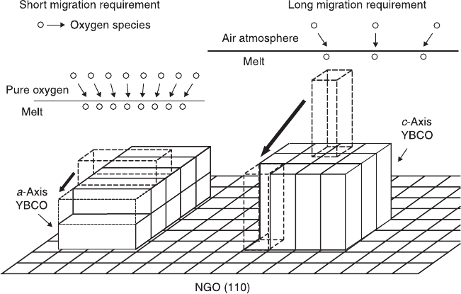
shorter migration to occupy the appropriate crystal growth site in a-axis growth
mode compared with the growth of c-axis film. It is well known that under
inadequate oxygen supply, vacancies in oxygen sublattice induce transformation
of entire lattice units, thus facilitating cation migration.
25
On the other hand, the
pure oxygen atmosphere increases the chemical potential of oxygen in the melt,
which should get into equilibrium with that in the surrounding oxygen gas. The
saturated oxygen state is thought to reduce the cation mobility, up to a ‘frozen’
state. Consequently, a-axis oriented growth was considerably enhanced.
In short, the oxygen factor manifested itself by promoting a-axis growth in the
YBCO system, and gradually became dominant in comparison with supersaturation,
which had played the most important role in promoting the a-axis growth so far.
SmBCO
The mechanism between a- and c-axis transition was consummated by Tang and
co-workers in the SmBCO system, who first reported that pure a-axis orientated
SmBCO films were grown by combination of Cu-rich flux and 1 atm oxygen
atmosphere. Compared to YBCO, it is more difficult to grow SmBCO a-axis film.
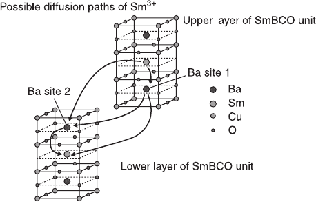
Several possible reasons were considered, especially the reversible substitution
between Sm
3+
and Ba
2+
, which may favor the c-axis growth. As mentioned above,
the c-axis growth needs a longer distance for the atoms to move to a suitable site
based on the migration theory. In the SmBCO system, due to that substitution, the
7.11 Surface migration model of the a- and c-axis YBCO films when
different oxygen partial pressures are applied.
Liquid phase epitaxy growth of HTSC films 291
1
2
3
4
5
6
7
8
9
10
1
2
3
4
5
6
7
8
9
20
1
2
3
4
5
6
7
8
9
30
1
2
3
4
5
6
7
8
9
40
1
2
43X
© Woodhead Publishing Limited, 2011
travel distance can be divided into several short jumps, with some possible
migration paths of Sm
3+
shown in Fig. 7.12. Importantly, it was reported that with
the increase of x in the Sm
1 + x
Ba
2 – x
Cu
3
O
7 –
δ
solid solution, the lattice parameter
of c-axis rapidly reduced, while that of a-axis showed only a little change,
26
which
led to a decrease of jump length of c-axis growth. Notice that the Cu-rich melt will
enhance that substitution, which is the reason why the melt of Ba/Cu = 3:7 does not
evidently support the a-axis growth in SmBCO, but in YBCO.
On the other hand, from the growth kinetics point of view, the interfacial energy
between SmBCO crystal and the melt is about 20% lower than that of YBCO.
27
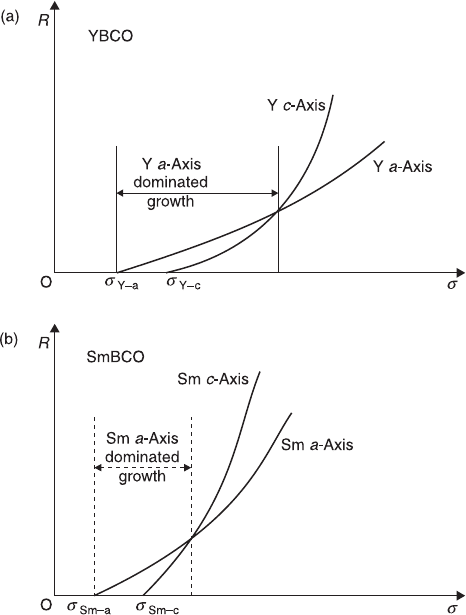
In other words, nucleation of SmBCO might occur at a small supersaturation,
which means, the ‘a-axis dominated growth region’ of SmBCO should move
towards a lower supersaturation area compared to YBCO. Furthermore, it is well
known that the liquid slope of samarium solubility in the solution is considerably
smaller than that of yttrium.
28
A small undercooling in the SmBCO system can
produce a large supersaturation, which can easily exceed the a-axis growth limits
and lead to a high growth rate of SmBCO. The high growth rate can cause both
a-phase and c-phase nuclei to grow into large grains in a short period of time. This
makes it difficult to isolate pure a-phase growth from the a/c mixed one.
Until now, discussions explaining the transition between a and c growth were
limited to the migration theory which is mainly associated with the thermal factors
such as temperature and supersaturation. However, besides those thermal factors,
the kinetic factors play a critical role. In vapor phase deposition (VPD), the
growth temperature is several hundred degrees below T
p
of REBCO. At such a
low temperature, the growth of both a- and c-axis grains is thermodynamically
allowed. In such a case, kinetic energy of the migrating atoms or ions is the
dominant factor determining the film orientation. The temperature range of the
a–c transition is usually around 100 degrees wide,
29,30
and in LPE, the growth
7.12 Schematic diagram of the influence of Sm
3+
and Ba
2+
substitution
on the diffusion path of Sm
3+
ions.
292 High-temperature superconductors
1
2
3
4
5
6
7
8
9
10
1
2
3
4
5
6
7
8
9
20
1
2
3
4
5
6
7
8
9
30
1
2
3
4
5
6
7
8
9
40
1
2
43X
© Woodhead Publishing Limited, 2011
condition is close to the thermodynamic equilibrium.
2
The kinetic energy of the
migrating atoms is no longer a limiting factor and the a–c transition happens
dramatically, within 10 degrees.
20,31–33
This does not allow for enough kinetic
energy difference necessary for the a–c transition.
Hence, other factors have to stand behind the kinetic limit of a–c transition in
LPE films. The time during which atoms can diffuse along the grain/flux interface
plays a critical role in the difference between LPE and VPD. Thus a more general
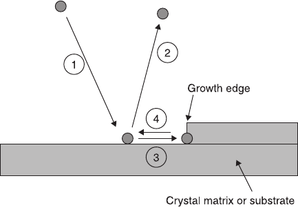
LPE mechanism on the growth kinetic was suggested. As shown in Fig. 7.13, the
situation is composed of four steps:
1 an atom from the environment attaches to the grain/flux interface;
2 the atom does not reach a suitable site on the growth edge and goes back to the
environment;
3 the atom reaches an appropriate site and becomes a part of the crystal matrix;
4 the atom diffuses on the interface.
Different from VPD, the atoms can effectively go back to the environment in LPE,
so both the diffusion time and the diffusion length are finite and important. Suppose
that t is the mean time that atoms can stay on the interface, t
c
is the average time
during which an atom reaches a growth site in c-axis growth and t
a
is the same in
a-axis growth, where t
c
is longer than t
a
according to the surface migration theory.
Consequently, if t > t
c
, LPE would produce a c-axis oriented film; if t
c
> t > t
a
, the
LPE would result in an a-axis oriented film. In this case, the diffusion time becomes
a controlling factor of the kinetic limit. Combining the diffusion time with the
thermodynamic factors, we can obtain results as a higher growth temperature can
provide more migration energy. Therefore the atoms can more easily escape from
the interface. On the other hand, a low supersaturation in the melt corresponds to a
low slope of the RE element concentration curve (the solute concentration profile
7.13 A schematic kinetic model of the surface migration in LPE.
Liquid phase epitaxy growth of HTSC films 293
1
2
3
4
5
6
7
8
9
10
1
2
3
4
5
6
7
8
9
20
1
2
3
4
5
6
7
8
9
30
1
2
3
4
5
6
7
8
9
40
1
2
43X
© Woodhead Publishing Limited, 2011
in the flux near the growth frontier of the crystal), which makes it easier for atoms
to return to the liquid and leads to an interfacial controlled growth mode.
34
These
two factors reduce the mean holding time t for atoms on the interface as temperature
increase. Therefore, a-axis growth can be obtained when under the conditions of
high growth temperature and small supersaturation. However, in an extreme case,
if the growth temperature is very close to T
p
a-axis grains may not appear because
of the weak thermal stability of a-axis film. Accordingly, on the other hand, the
kinetics play a key role when there is supercooling (∆T) of more than 10 K.
In conclusion, combining the effect of both thermodynamic and kinetic factors,
this model offers a new way in understanding the mechanisms of a–c growth
transition in REBCO.
7.3.2 Pinning structure and growth mechanism of
a /c axes REBCO films
We have discussed the a and c growth of the REBCO-LPE films due to their
considerable anisotropy. Besides, an a/c mixed structure is also very attractive.
The a/c grain boundary may possibly serve as a connection instead of the
conventional SIS structure or as a source of flux pinning.
35
Tang presented some different a/c mixed LPE films both in pure SmBCO and
mixed Y-Sm systems by controlling growth conditions. For the reasons that the
c-axis films are not usually flat and clean due to the high growth rate of SmBCO
and a-oriented grains are too small to observe in the YBCO system, we focus on
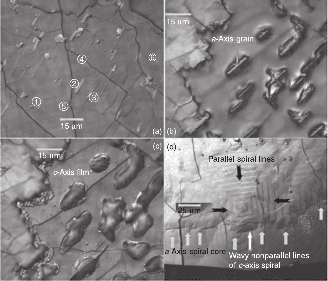
the Y-Sm mixed system. Figure 7.14 demonstrates the morphology of different
kinds of a/c grain boundaries on (Y, Sm) BCO-LPE film. Figure 7.14(b) and (c)
shows different details of the same image taken on the film grown from the 3:5
flux in a pure oxygen atmosphere. Figure 7.14(b) focuses on rod-like a-axis
grains, while (c) is focused on platelet-like c-axis grains. Obviously, the distance
between the levels of a- and c-grain tops is larger than the microscope’s depth of
field, so the microscope could not focus on both grain types at the same time.
Figure 7.14(a) shows a-oriented grains isolated in the c-axis film, while the
rectangular growth spiral and the typical c-axis twinning demonstrate the film
orientation. The a-axis grains seem to be trapped by the c-oriented film. Grains
marked as
1, 2, and 3 are partially covered, while grains 4, 5 and 6 are almost buried
in the film. It directly proves that the c-oriented grains grow faster and cover the
a-oriented grains. As Shingai et al. mentioned,
34
this kind of a/c boundary might
be a potential source of flux pinning. Figure 7.14(d) shows an edge of the film,
from which we can see that the c-axis oriented film has the tendency to cover the
a-axis growth and the a-axis elliptical spiral cores lie on the a/c boundary. Maybe
the reason is that the core of a growth spiral always has the highest growth rate
and stands on the top, which prevents the c-oriented film from growing over.
With analogy to the growth mode of the a–c transition, we suppose that
supersaturation plays an important role in the growth of a/c grain boundaries in
294 High-temperature superconductors
1
2
3
4
5
6
7
8
9
10
1
2
3
4
5
6
7
8
9
20
1
2
3
4
5
6
7
8
9
30
1
2
3
4
5
6
7
8
9
40
1
2
43X
© Woodhead Publishing Limited, 2011
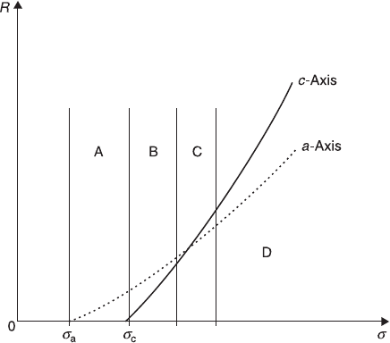
the Y-Sm system. It may be helpful to understand the scenario according to the
schematic illustration shown in Fig 7.15. Since the supersaturation is related to
supercooling, the tendency of
δ
A
>
δ
B
>
δ
C
>
δ
D
is clear, although we did not
know the exact supersaturation. Thus, when supersaturation lies in region A or D,
pure a or c growth can be obtained. While in region B, the a-axis grains grow over
the c-axis ones because the growth rate of a-oriented grains is higher than that of
c-oriented ones. Henceforward, this kind of growth mode is defined as the α-mode.
On the other hand, the β-mode was denoted when supersaturation was set into
region C, in other words, the a- and c-oriented grains had similar growth rates.
The differences between the two modes are demonstrated in Fig 7.16. When films
grow in the α-mode because of the high growth rate of a-axis grains, the standing
ones disturb the solvent convection, leaving the space filled with a trapped flux
instead of forming an a/c boundary. In contrast, the nutrient flow can easily reach
7.14 Morphology of different kinds of a–c grain boundaries on the
(Y, Sm) BCO-LPE film. The growth parameters (temperature, Ba:Cu
ratio, atmosphere) were: (a) 1037 °C, 3:5, O
2
; (b, c) 1043 °C, 3:5, O
2
;
(d) 1020 °C, 3:5, air. The scale bar in (d) is different from the other
three, because the picture was taken under a different
magnification level.
Liquid phase epitaxy growth of HTSC films 295
1
2
3
4
5
6
7
8
9
10
1
2
3
4
5
6
7
8
9
20
1
2
3
4
5
6
7
8
9
30
1
2
3
4
5
6
7
8
9
40
1
2
43X
© Woodhead Publishing Limited, 2011
the growth frontier when growing in the β-mode. As a result, a fine a/c mixed
structure can be obtained as presented in Fig 7.14(a) and (d). Note that the grains
orientation is very sensitive to growth conditions, which lead to an extraordinarily
narrow growth window for a fine a/c mixed structure.
What is important is that the combination between the a/c axis boundaries is
believed to be very tight. Additionally, the a-axis grains are coherently oriented
due to the differences of lattice constant between the a-axis grain and the
substrate,
36
which will not prevent the flow of current since the current may flow
along the long axes of a-oriented grains. These make the a/c mixed structure an
effective pinning centre which can improve the properties of a superconductor in
the field.
7.3.3 The thermal stability of REBCO films
Recently, the superheating phenomenon has been of great concern. If heterogeneous
nucleation at free interfaces or grain boundaries is suppressed, crystals could be
superheated above their equilibrium melting points, which was the so-called
superheating.
28,37–39
In 1986, the superheating phenomenon was first reported by Daeges et al.
28
in
the Ag system, and in 2000, superheating in trapped Pb two-dimensional film was
found by Zhang et al.
34
and a new superheating mode was established. But the
research above were limited to the metal or its alloy materials until the discovery
7.15 A schematic grain growth rate diagram, R vs supersaturation.
The y-axis represents the growth rate (R), the x-axis represents the
supersaturation (
σ
).
296 High-temperature superconductors
1
2
3
4
5
6
7
8
9
10
1
2
3
4
5
6
7
8
9
20
1
2
3
4
5
6
7
8
9
30
1
2
3
4
5
6
7
8
9
40
1
2
43X
© Woodhead Publishing Limited, 2011
of the superheating phenomenon in YBCO/MgO thin film in the YSNG (YBCO
seeded NdBCO growth by LPE).
35,40
The most important criterion of the hetero-
seed growth is that the seed material should have a higher melting temperature
than the processing one. While in this instance the behavior is plainly opposite to
the general conception, this so-called hetero-seeded growth can be extended to a
wider application, not only suitable for all REBCO and mixed REBCO systems,
but also for other seed-required HTS processes. The application of superheating
in acquiring superconductor materials attracts much interest.
The mechanism of hetero-seed LPE growth using YBCO-thin-film as a seed
In order to study the mechanism of YSNG, a vertically-dipping experiment
35,41
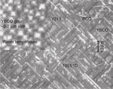
was conducted with a continuous traveling mode. Figure 7.17 shows an optical
micrograph of a vertically-dipped LPE specimen in the undipped region with an
7.16 Schematic illustration of the differences in the LPE process in
(a) YBCO and (b) SmBCO. The y-axis represents the growth rate (R),
the x-axis represents the supersaturation (
σ
).
Liquid phase epitaxy growth of HTSC films 297
1
2
3
4
5
6
7
8
9
10
1
2
3
4
5
6
7
8
9
20
1
2
3
4
5
6
7
8
9
30
1
2
3
4
5
6
7
8
9
40
1
2
43X
© Woodhead Publishing Limited, 2011
AFM image of the vapor-deposited YBCO-seed on the upper left side. When the
specimen was put into the liquid, the YBCO grains underwent heating from room
temperature to 1055 °C, which is higher than the peritectic temperature (~1010 °C)
of YBCO, and became thermodynamically unstable. Consequently, Y211 grains
and solidified Ba-Cu-O (BCO) melts can be observed, which are the products of
the YBCO decomposition. Needle-shaped Y211 grains with the c-axis in a long
length direction
42
are well aligned on the MgO substrate due to a good lattice
matching. On the other hand, the undecomposed YBCO particles are clearly
visible, implying a superheating phenomenon since they endured a higher
processing temperature than the T
p
of YBCO. The epitaxial relation between
YBCO and NdBCO grains can be confirmed. First, NdBCO grains morphologically
exhibit a squared shape, indicating the 0°-oriented NdBCO grain on the MgO
substrate, which behaves the same as the YBCO seed-grain on MgO. Secondly,
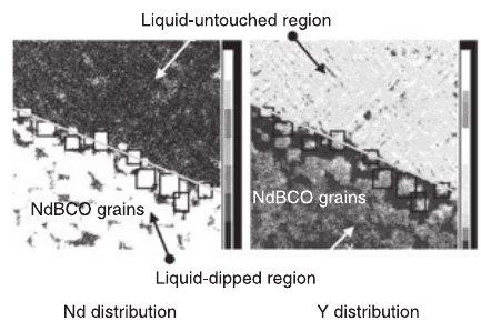
the EPMA mapping analysis was used to determine the Y and Nd distribution near
the dipping boundary. It was found that there are Yttrium-segregated regions close
to the boundary in the dipped side. These concentrated-Y regions are visible
only and exactly underneath the initially grown NdBCO grains as displayed in
Fig. 7.18. All information suggests that these Y-segregated regions are previous
YBCO grains, which act as hetero-seeds for the growth of NdBCO grains. This
confirmed existence of the Y element from the initially grown NdBCO grains
provides direct evidence that NdBCO-LPE films could grow from YBCO film-
seeds at a higher processing temperature than the T
p
of YBCO.
Additionally, the YBCO-thin-film seeded LPE thick-film growth also
succeeded in other systems, including: SmBCO (T
g
: 1020~1057 °C); and mixed
7.17 An optical micrograph showing microstructures of a vertically-
dipped specimen in the undipped region with an AFM image showing
YBCO seed-film structure on the upper left side.
298 High-temperature superconductors
1
2
3
4
5
6
7
8
9
10
1
2
3
4
5
6
7
8
9
20
1
2
3
4
5
6
7
8
9
30
1
2
3
4
5
6
7
8
9
40
1
2
43X
© Woodhead Publishing Limited, 2011
RE123 systems of Ni-NdBCO (T
g
: ~1057 °C), Sr-NdBCO (T
g
: ~1057 °C),
Nd-YBCO (T
g
: 1000~1030 °C), Yb-YBCO (T
g
: 970~980 °C), Ca-YBCO (T
g
:
957~980 °C) and Zn-YBCO (T
g
: 966~984 °C). In those REBCO LPE processes,
YBCO film became universal seeds. It should be pointed out that a severe
dissolution of YBCO seed grains may take place when a high processing
temperature and a non-Y liquid were used. In contrast, the YBCO hetero-seed
produces insignificant seed dissolution when a low processing temperature (lower
than the T
p
of YBCO) and a Y-saturated liquid were employed.
The mechanism of the high stability of YBCO thin film
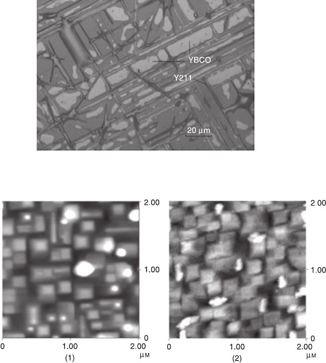
To understand the superheating mechanism of YBCO thin films, the melting
process of the films was observed by high-temperature optical microscopy
(HTOM), which offered a direct proof of the high thermal stability of YBCO thin
films. It was found that the YBCO/MgO thin film can be substantially superheated
above the peritectic temperature of YBCO (at least 50 °C) for 3 min at a heating
rate of 5 °C/min to 1060 °C,
40
as shown in Fig. 7.19. Three factors have been
mainly considered to explain this superheating phenomenon. First, the film was
c-oriented. It is well known that due to the anisotropy of the YBCO crystals, the
lowest-energy (001) free surface plays an important role in the superheating
phenomenon of YBCO film. Secondly, the semi-coherent bonding suppresses the
heterogeneous melting nucleation at the interface, leading to a low-energy
interface between them. Thirdly, the Ba-Cu-O liquid wets neither the parent phase
of Y123 nor the MgO substrate, which causes a liquid migration from the melting
front. A continuous driving force for nucleation of melting is required after the
Ba-Cu-O liquid migrates away. Moreover, a locally low temperature region was
7.18 EPMA mapping images showing Y and Nd distributions at the
boundary between the undipped region on the top and the dipped
region on the bottom.
Liquid phase epitaxy growth of HTSC films 299
1
2
3
4
5
6
7
8
9
10
1
2
3
4
5
6
7
8
9
20
1
2
3
4
5
6
7
8
9
30
1
2
3
4
5
6
7
8
9
40
1
2
43X
© Woodhead Publishing Limited, 2011
induced owing to the endothermic reaction of Y123 melting. In brief, all the
above-mentioned three points may cause a delay to melting.
Besides, further studies of in situ observation of the melting process of YBCO
thin films with different microstructures and crystallinity were taken to have more
insights into the high thermal stability of YBCO. The c-axis films were denoted
as A and B according to their degree of crystallinity. As illustrated in Fig. 7.20, the
YBCO grains in film A have a relatively regular square shape, while the shape of
the grains in film B are twisted. Besides, the a-axis oriented YBCO grains are
only visible in film A. As can be seen in Fig. 7.21, the two films exhibited different
evolutions in their melting progresses. Furthermore, film A can be superheated up
7.19 An optical microscope showing microstructure of a sample at
1060 °C for 3 minutes.
7.20 AFM images presenting the microstructures of YBCO thin films:
(1) sample A; (2) sample B.
